This document provides an overview of Autodesk Inventor Series 11, including:
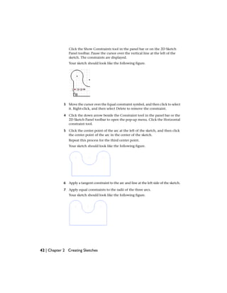
- Getting started information such as file types, application options, and styles/standards
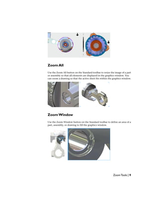
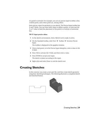
- How to view and manipulate models using zoom, pan, rotate, and other tools
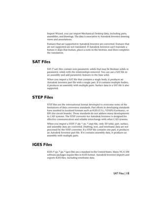
- Importing and exporting various file formats like AutoCAD, Mechanical Desktop, SAT, STEP, and IGES
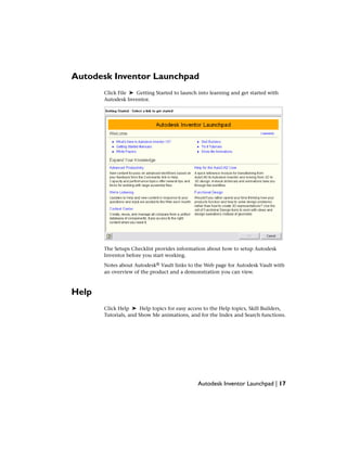
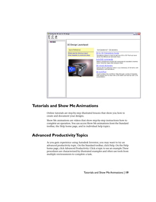
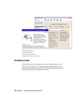
- Resources for learning Inventor such as tutorials, help documents, and skill builders