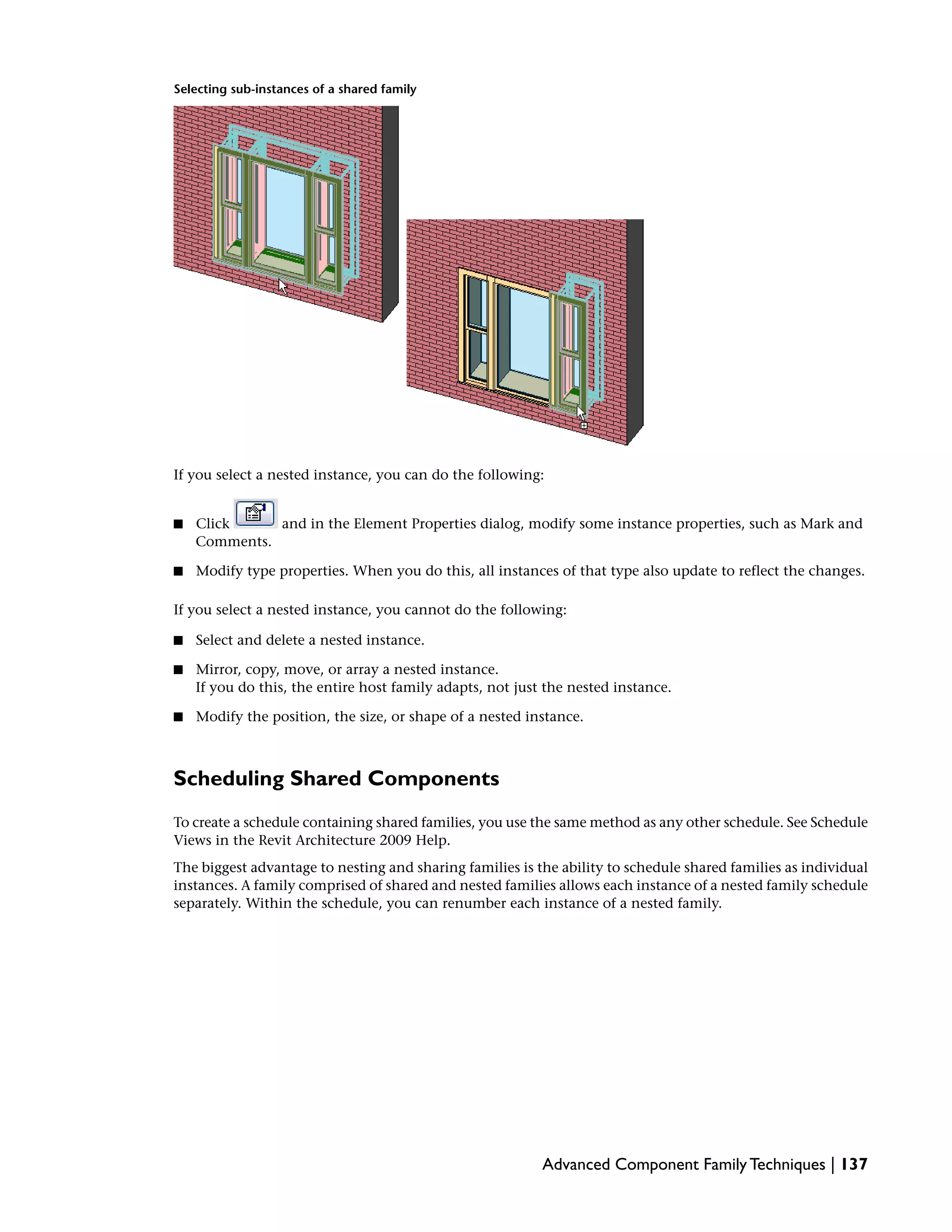
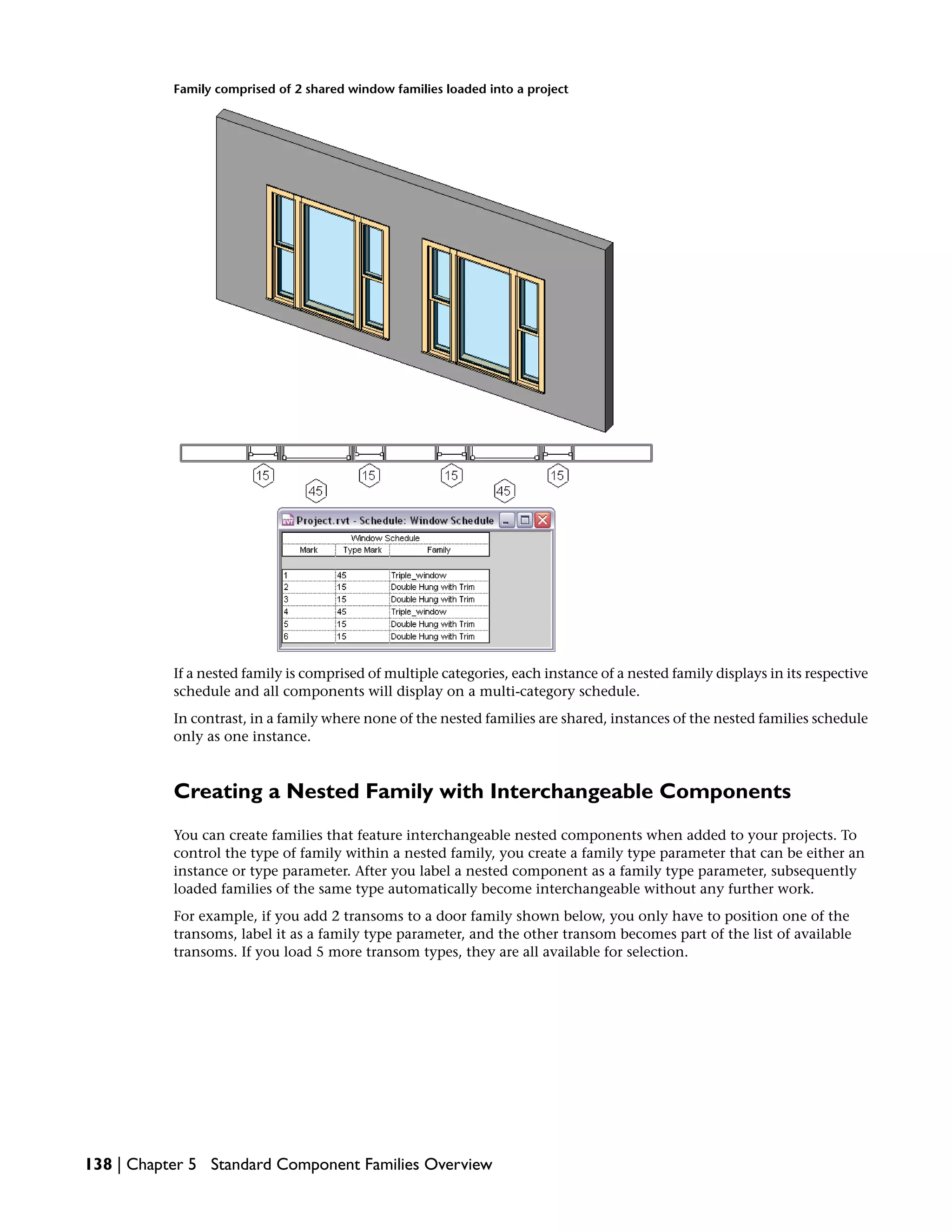
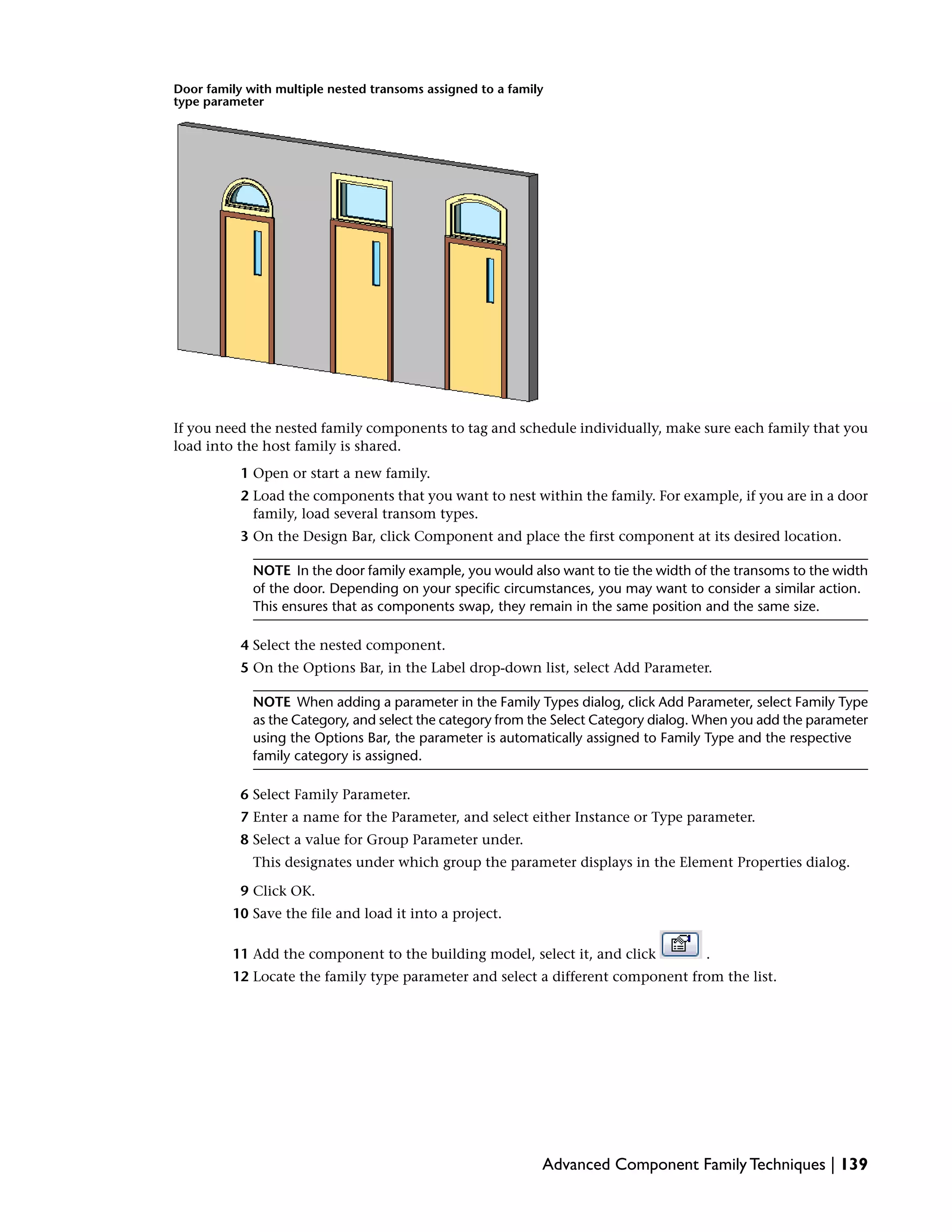
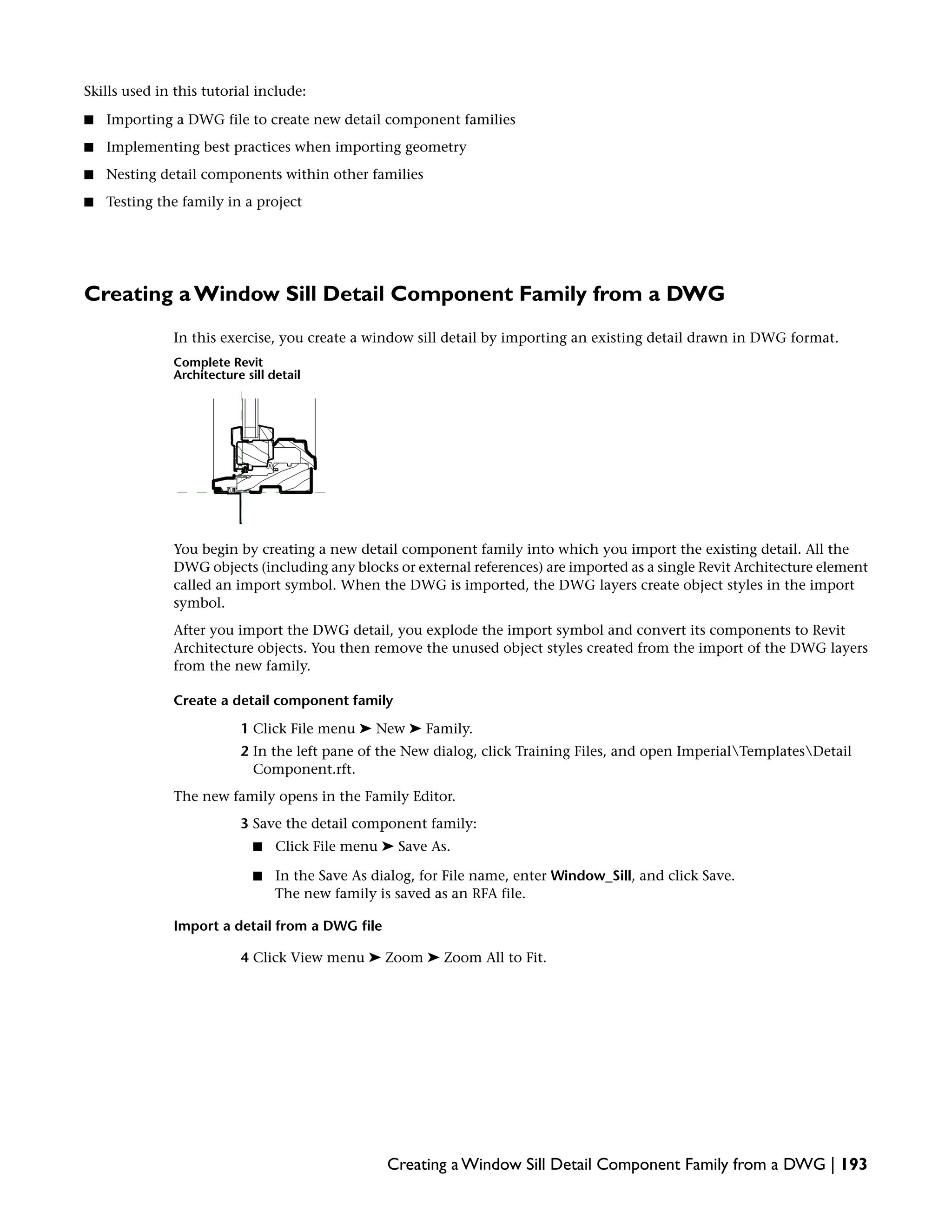
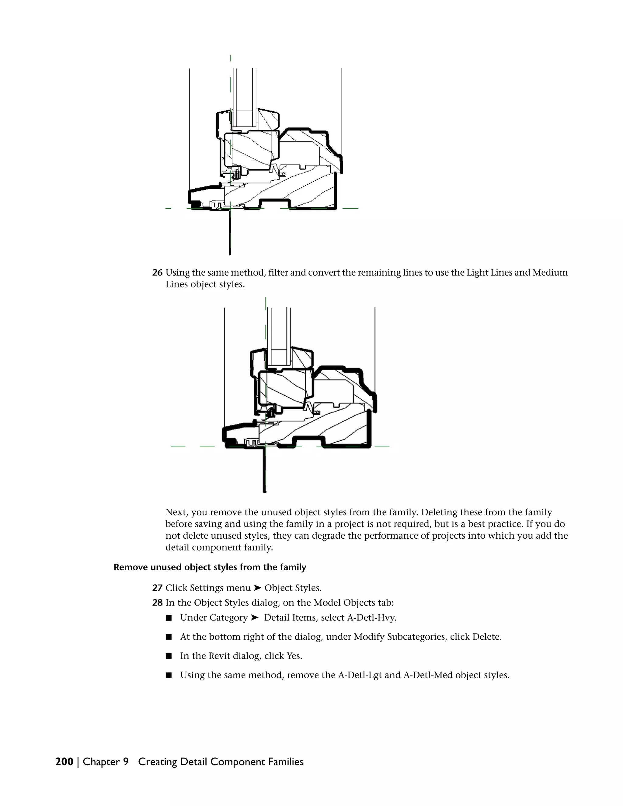
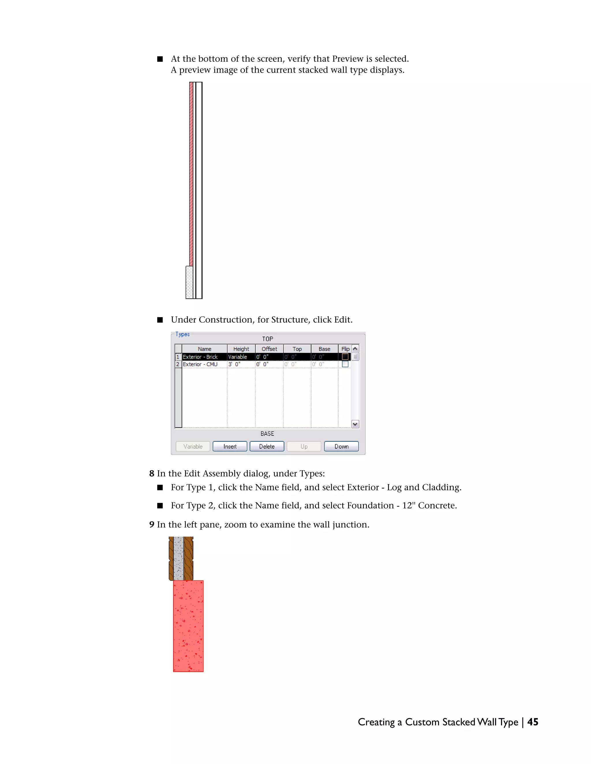
This document provides an overview and tutorial for Revit Architecture 2009 families. It discusses what families are in Revit and their role in building models. The different types of families - system, standard component, and in-place - are described. Guidelines are provided for getting started with families and using the design environment to create them. The first chapters also cover system families and provide a system families overview.


![You do not need to keep interior finish layers. To delete a layer, select the layer number, and
click Delete.
16 Add new materials and parameters to the remaining wall layers:
■ For layer 1, Finish 1[4], click in the Material field, and click .
■ In the Materials dialog, under Name, select Finishes - Exterior - Proprietary, Log, and click
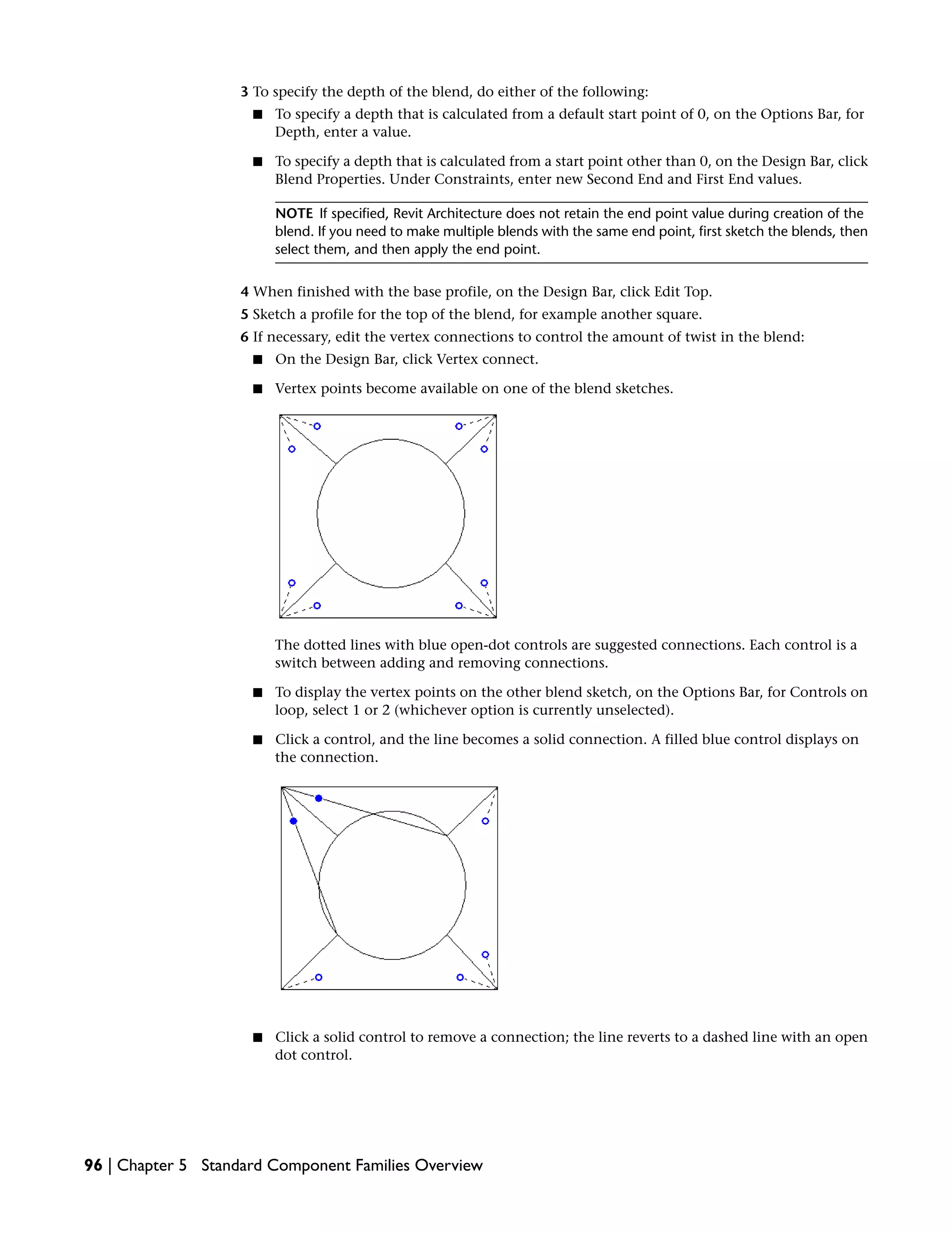
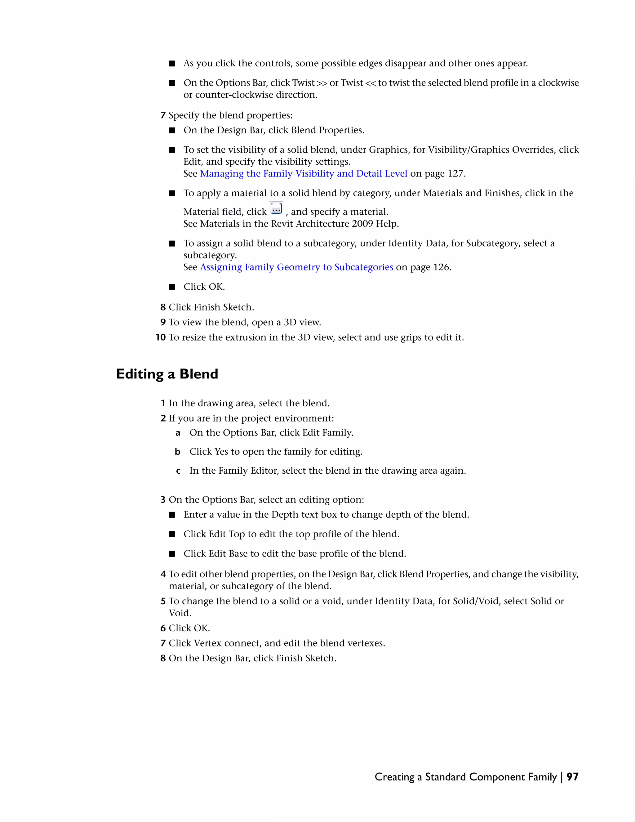
OK.
■ Click in the Thickness field, and enter 1-3/4''.
■ Clear Wraps.
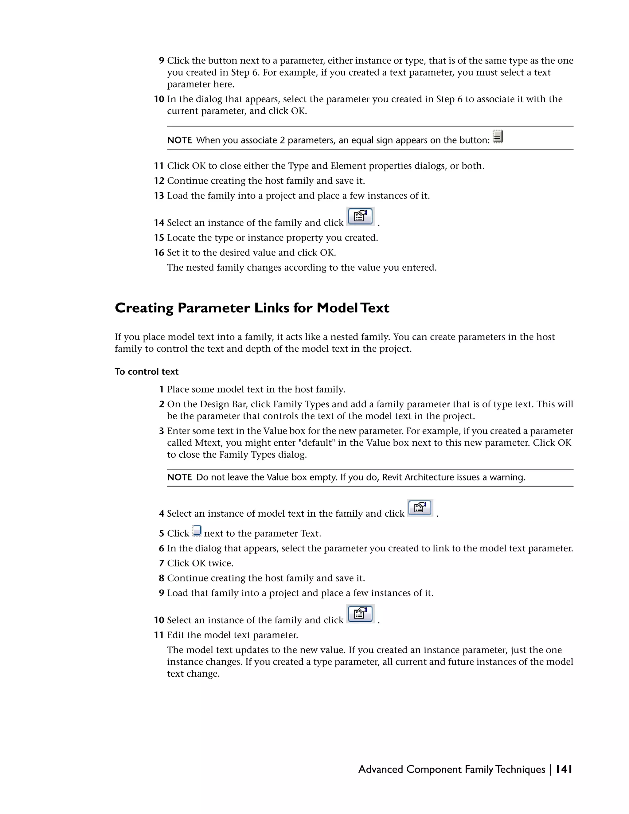
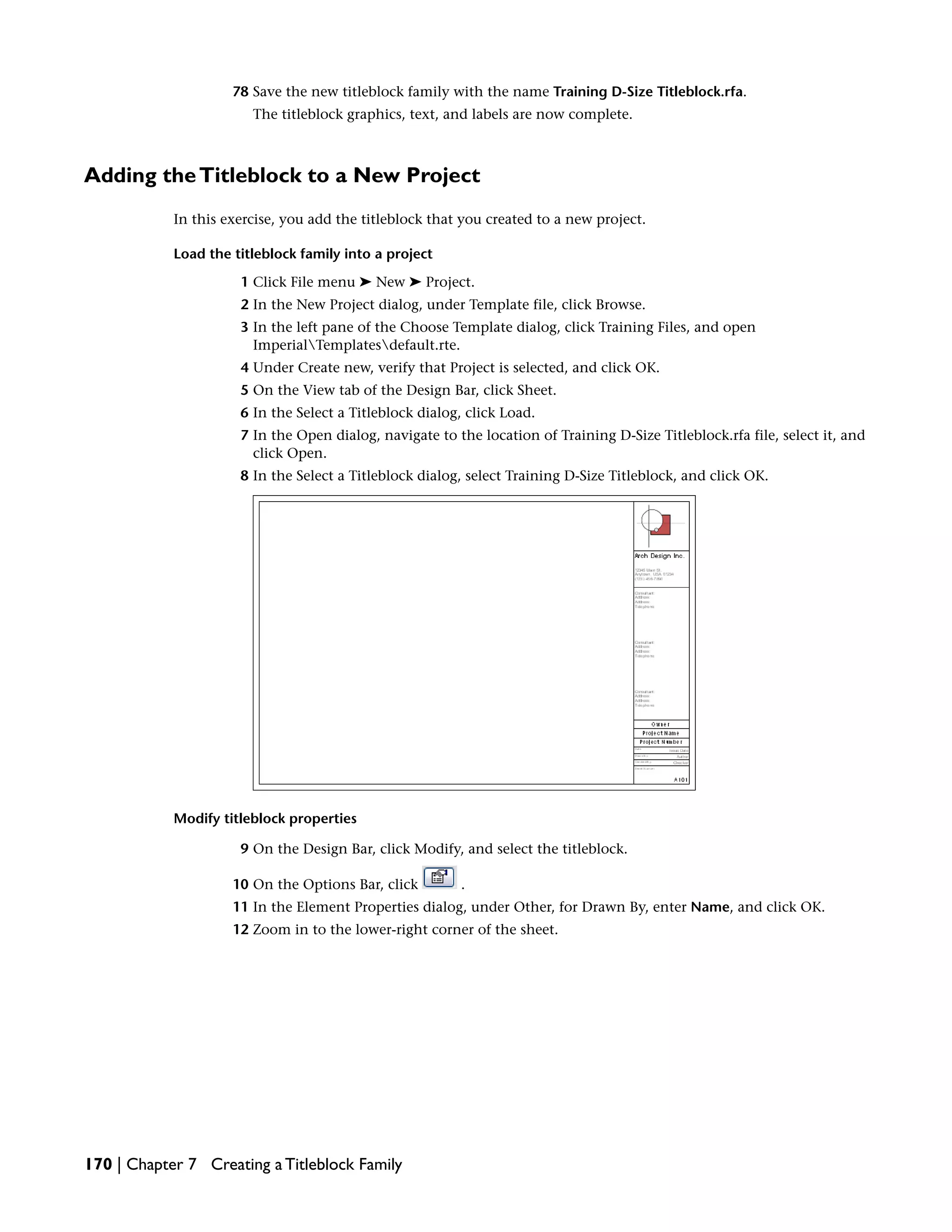
■ For layer 4, Structure [1], click in the Material field, and click .
■ In the Materials dialog, under Name, select Finishes - Exterior - Proprietary, Log, and click
OK.
■ For Thickness, enter 3 3/4''.
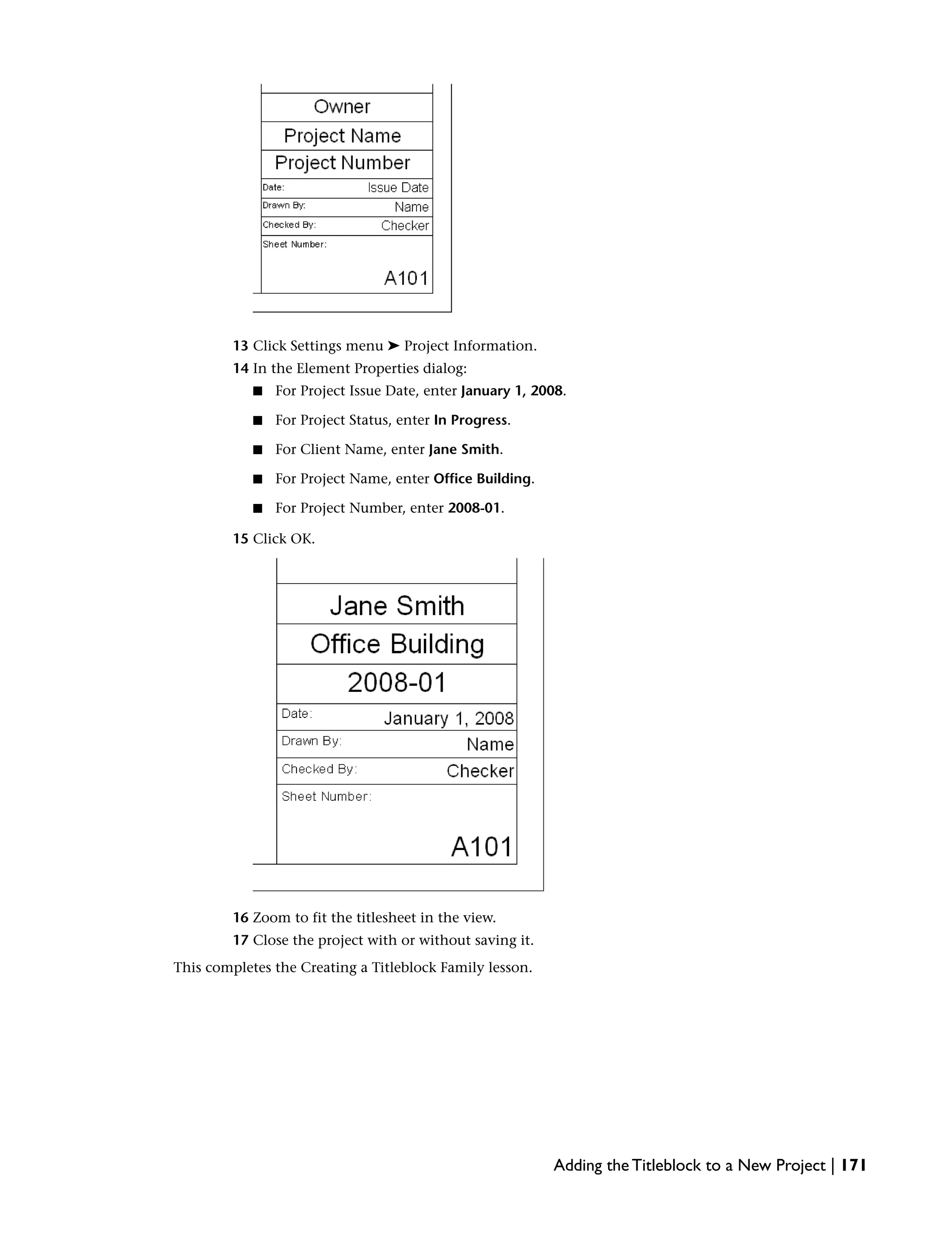
■ For layer 2, Thermal/Air Layer [3], click in the Material field, and click .
■ In the Material dialog, under Name, select Insulation/Thermal Barriers - Proprietary, Log
Wall, and click OK.
■ For Thickness, enter 4''.
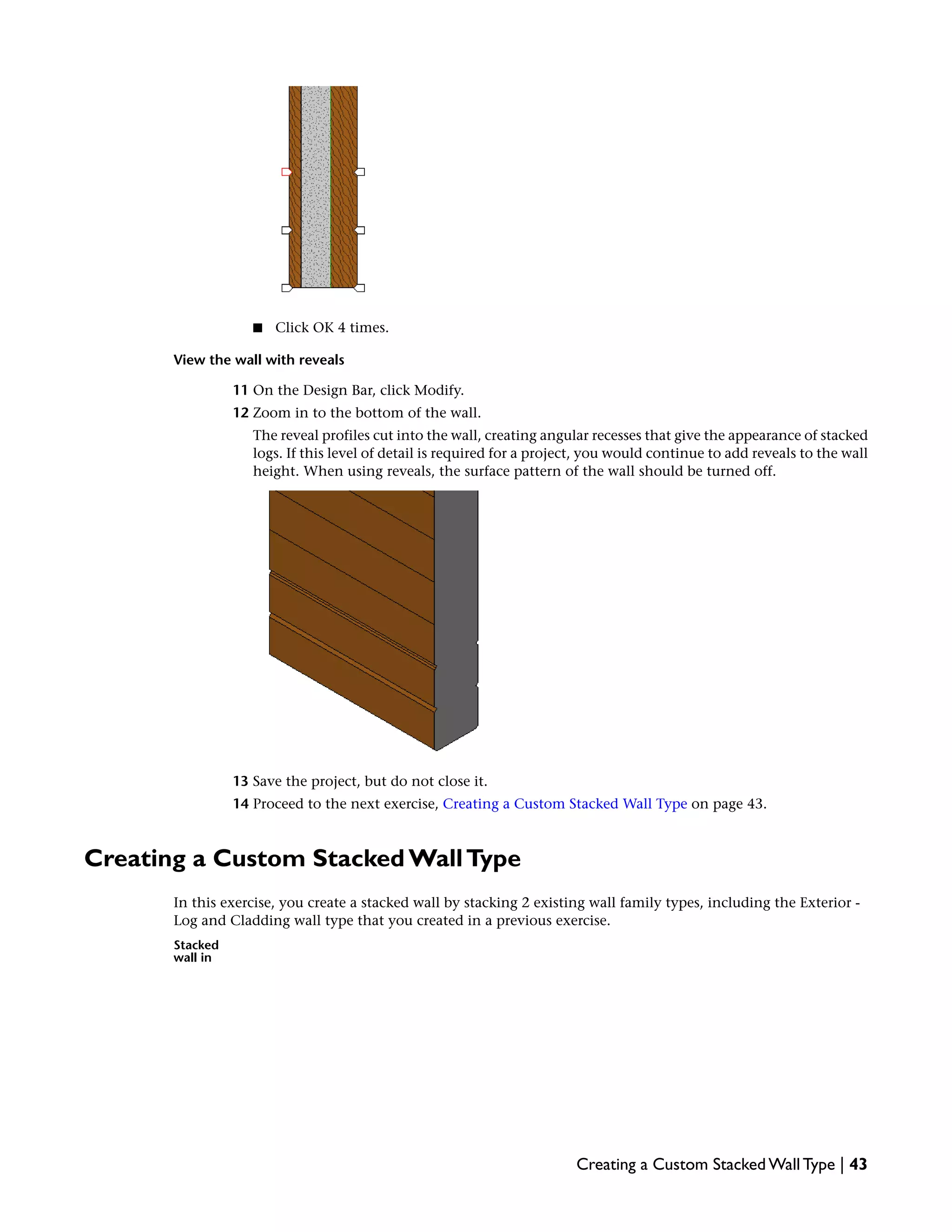
The Layers list now features only the layers that you need for the custom wall.
17 Click OK 3 times.
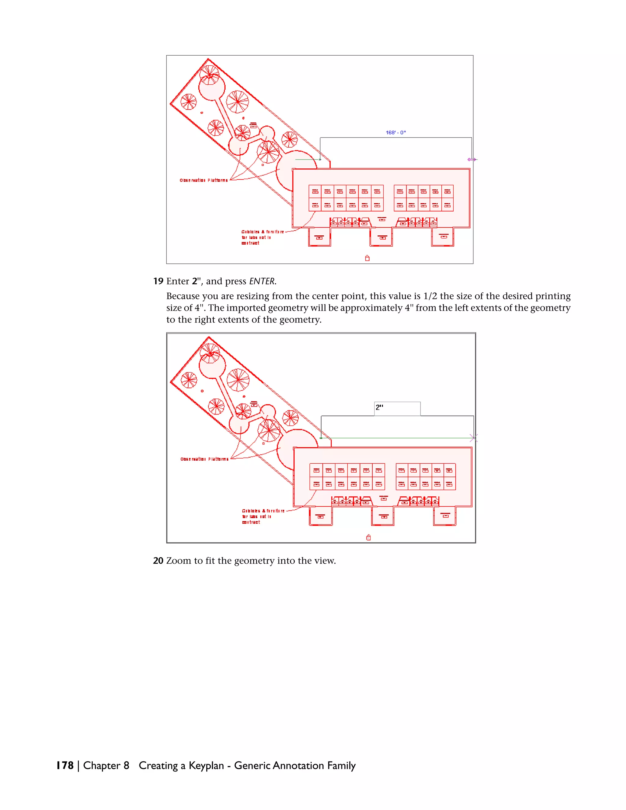
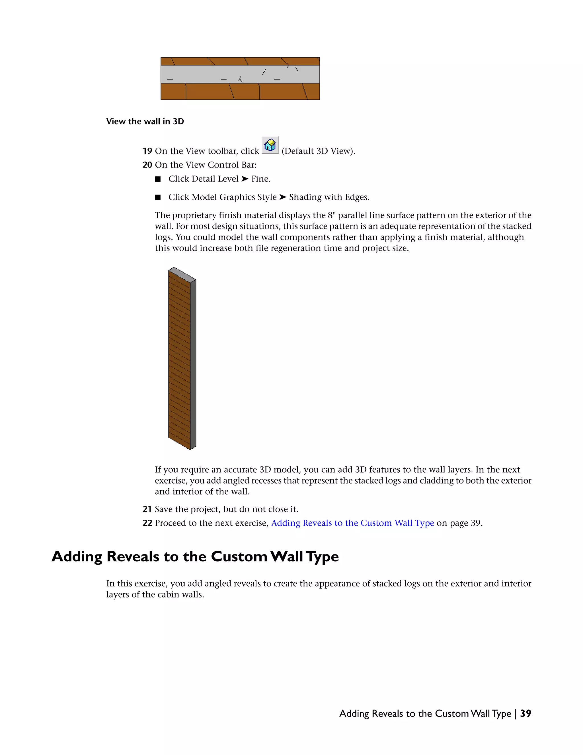
18 On the Design Bar, click Modify.
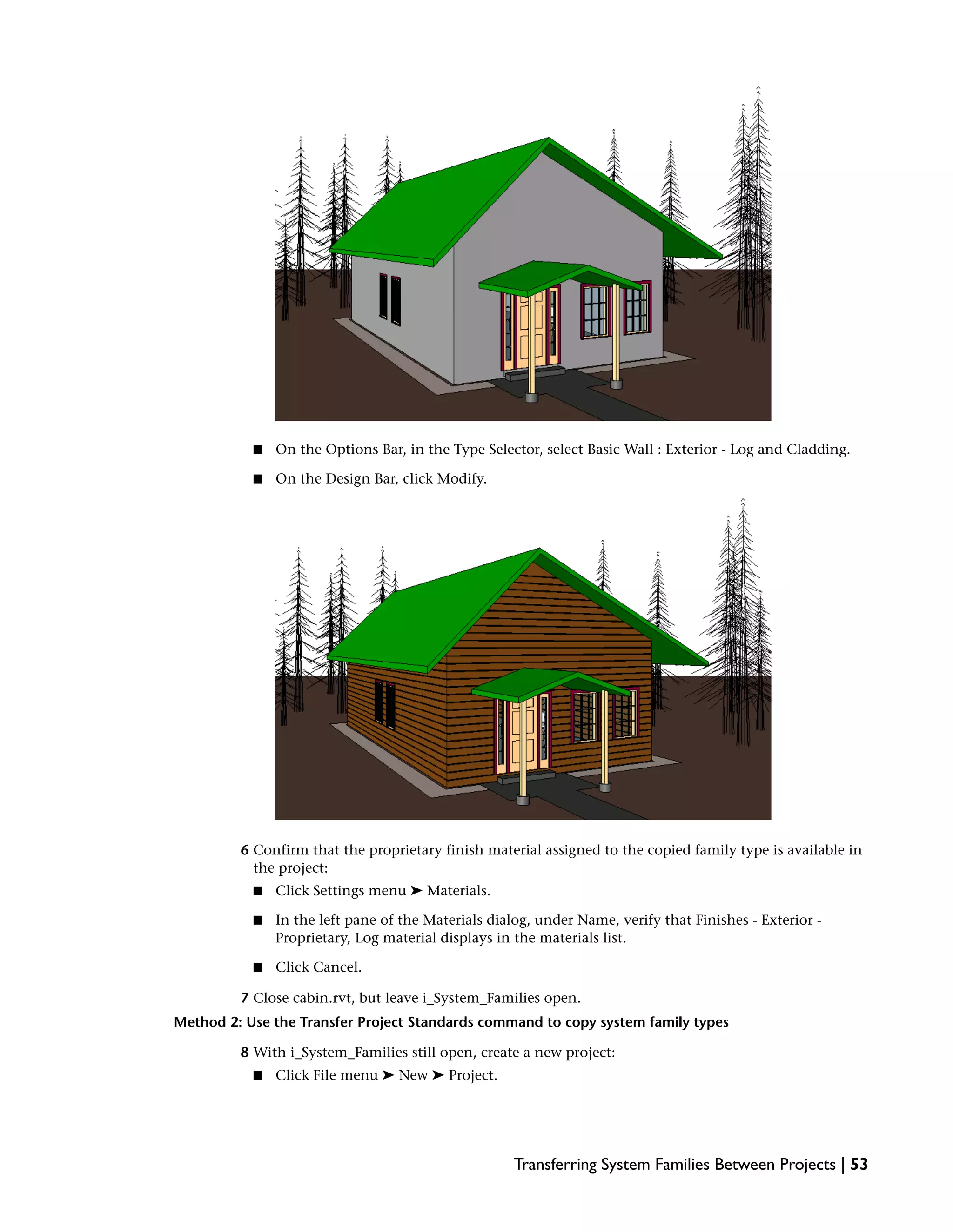
The wall in the project now features the new wall type. Wood and insulation patterns show in
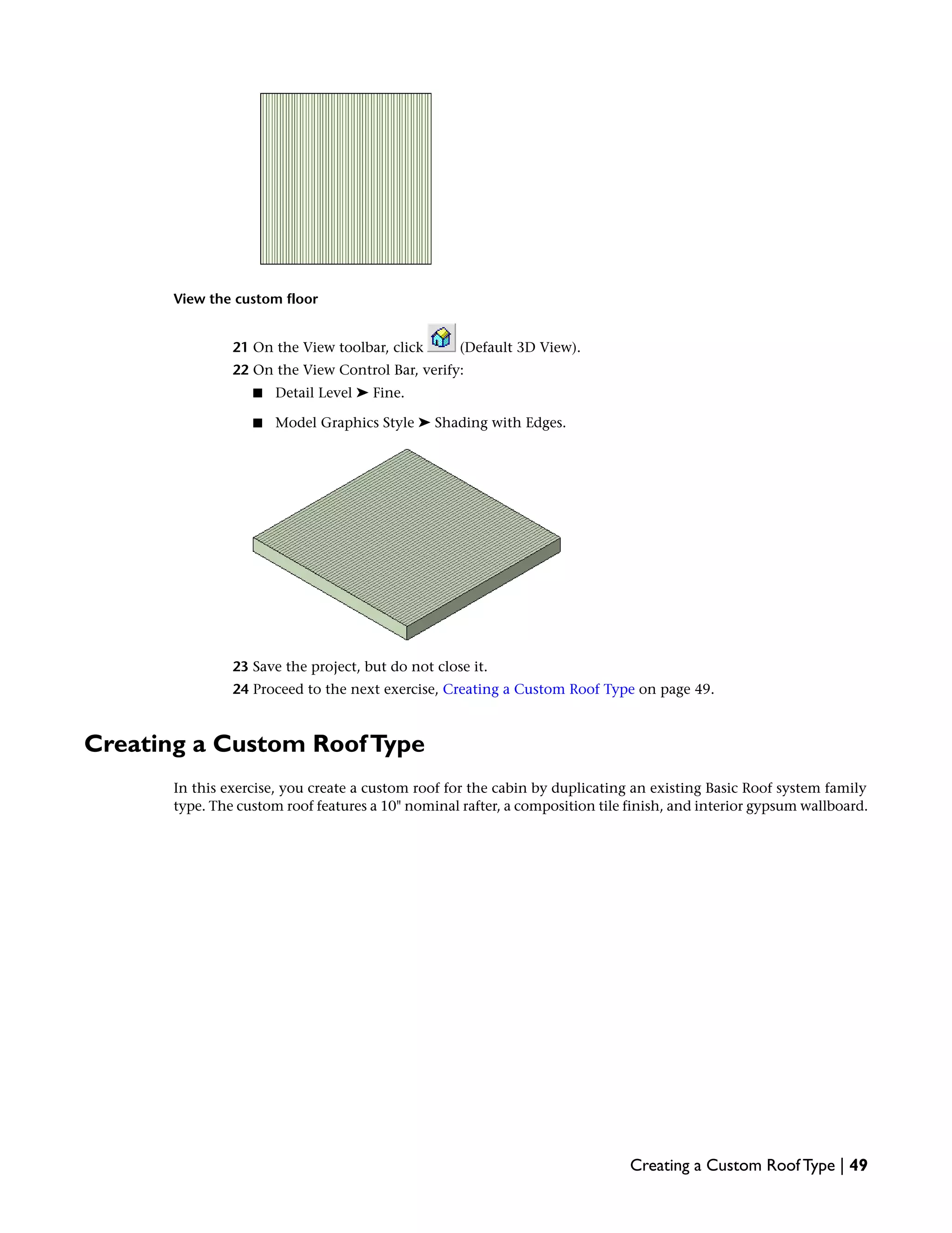
plan for each wall component.
38 | Chapter 4 Tutorial:Working with System Families](https://image.slidesharecdn.com/masterrevitfamily-170209064629/75/Tai-li-u-t-h-c-Family-trong-Revit-ph-n-1-48-2048.jpg)


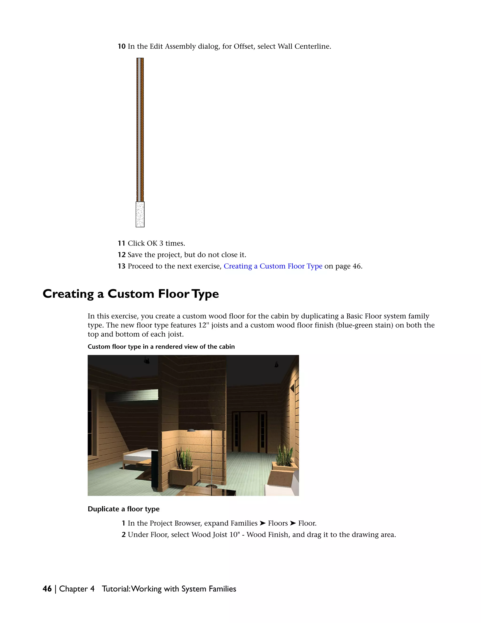

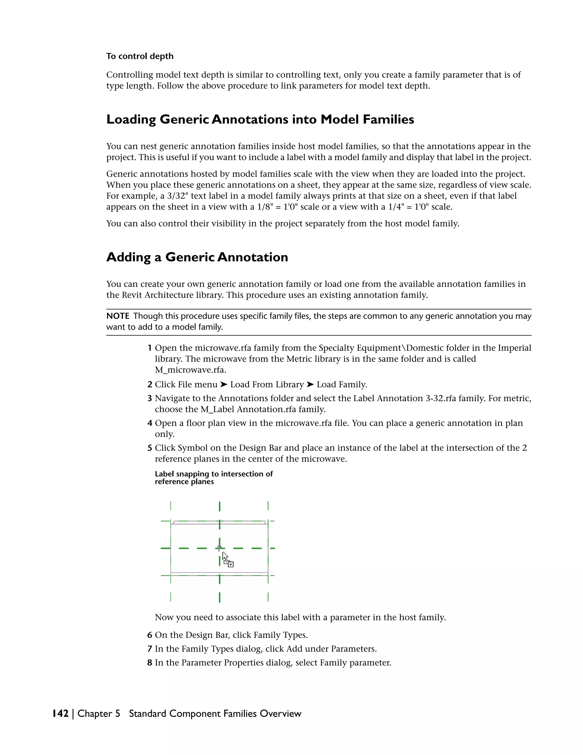
![A preview image of the duplicated floor displays.
Modify the floor assembly
18 In the Edit Assembly dialog, under Layers:
■ For layer 4, click in the Thickness field, and enter 11 3/4''.
■ For layer 1, click in the Material field, and click .
■ In the left pane of the Materials dialog, select Wood Flooring - Proprietary, and click OK.
19 Add a new layer to the floor assembly:
■ At the bottom of the Layers pane, click Insert.
■ With the new layer selected, click Down until the new layer is located at the bottom of the
list, below the Core Boundary.
■ For the new layer 6, click in the Function field, and select Finish 1 [4].
■ Click in the Thickness field, and enter 3/4''.
■ Click the Material field, and click .
■ In the left pane of the Materials dialog, select Wood Flooring - Proprietary.
■ Click OK 4 times.
20 On the Design Bar, click Modify.
48 | Chapter 4 Tutorial:Working with System Families](https://image.slidesharecdn.com/masterrevitfamily-170209064629/75/Tai-li-u-t-h-c-Family-trong-Revit-ph-n-1-58-2048.jpg)

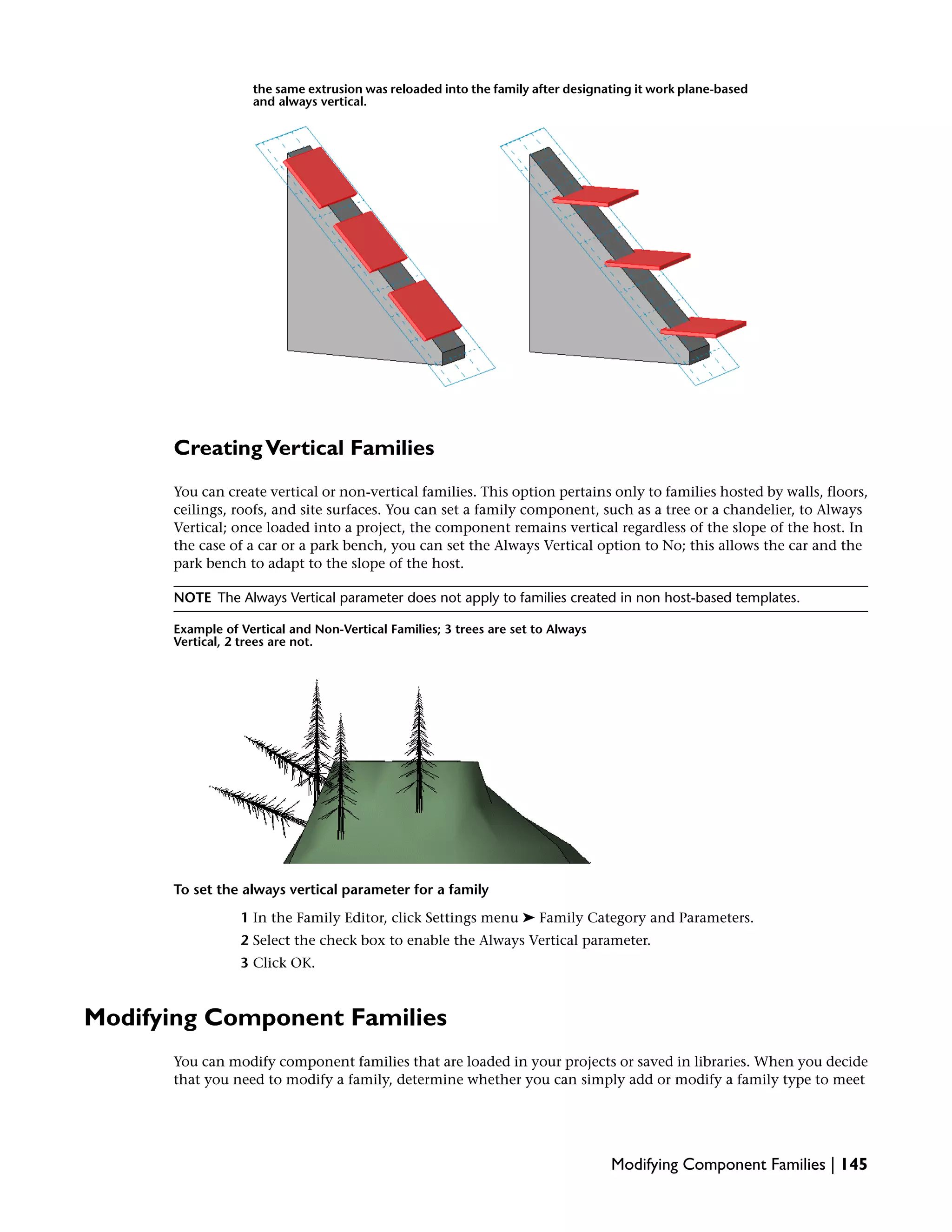
![A preview image of the duplicated roof type displays.
Modify the roof type assembly
14 In the Edit Assembly dialog, under Layers:
■ For layer 4, Structure [1], click in the Thickness field, and enter 9 3/4".
■ For layer 1, Finish 1 [4], click in the Material field, and click .
■ In the left pane of the Materials dialog, select Roofing - Composition Shingle, Proprietary,
and click OK.
15 Add a new layer to the roof assembly:
■ At the bottom of the Layers pane, click Insert.
■ With the new layer selected, click Down until the layer is located at the bottom of the list,
below the Core Boundary.
■ For the new layer 6, click in the Function field, and select Finish 1 [4].
■ Click in the Material field, and click .
■ In the left pane of the Materials dialog, select Gypsum Wall Board.
■ Click OK.
■ For layer 6, click in the Thickness field, and enter 5/8''.
■ Click in any of the fields to update the preview.
■ Click OK twice.
16 Save and close the project.
17 Proceed to the next exercise, Transferring System Families Between Projects on page 51.
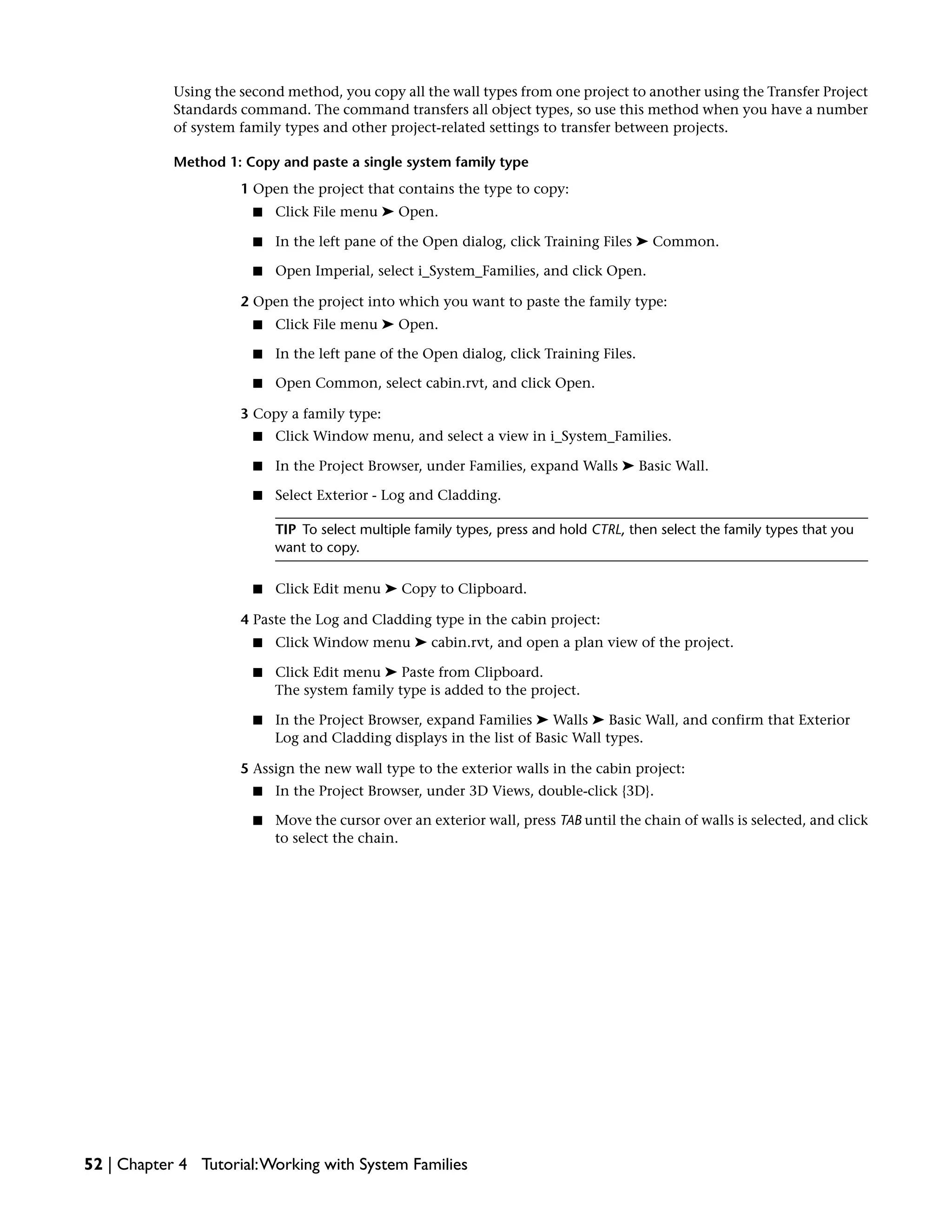
Transferring System Families Between Projects
In this exercise, you learn 2 different methods of transferring system family types from one project to another.
Using the first method, you copy a single wall type from one project and paste it into another, where you
apply it to a wall. Use this method when you need to transfer only a few specific types from project to project.
Transferring System Families Between Projects | 51](https://image.slidesharecdn.com/masterrevitfamily-170209064629/75/Tai-li-u-t-h-c-Family-trong-Revit-ph-n-1-61-2048.jpg)