Downloaded 14 times


![Depending on the current environment, two or more directories may be the
same.
If a file is not in this search path, you must specify both its path name and
file name before AutoCAD can find it. For example, if you want to insert the
part5.dwg drawing into your current drawing and it is not in the library search
path, you must specify its full path name, as shown here:
Command: insert
Enter block name or [?]: /files2/olddwgs/part5
If the drawing exists in that location, AutoCAD prompts you to finish the
INSERT command in the usual manner.
Directory Structure
AutoCAD uses tree-structured directories and subdirectories. It is recommended
that you keep supplemental files (such as AutoLISP applications and
customization files) separate from the AutoCAD program and support files.
This makes it easier to track possible conflicts and to upgrade each application
without affecting the others.
The default location for AutoCAD is in the Program Files folder. You can create
a new directory on the same level (for example, /AcadApps) and store your
custom AutoLISP and VBA macros, customization files, and other third-party
applications in subdirectories on the next level. If you want to maintain
multiple drawing directories (for separate job files), you can create a directory
such as /AcadJobs with subdirectories for each job.
Command Search Procedure
When you enter a command, AutoCAD goes through a series of steps to
evaluate the validity of the command name. A command can be a built-in
command or system variable, an external command or alias defined in the
acad.pgp file, or a user-defined AutoLISP command. Commands can also be
defined by ObjectARX applications or a device driver command. You can enter
a command on the command prompt or choose a command from the
appropriate menu. Commands can also be entered from a script file or by an
AutoLISP or ObjectARX application.
The following list describes the search order AutoCAD uses to validate a
command name.
1 If the input is a null response (SPACEBAR or ENTER), AutoCAD uses the
name of the last command issued. HELP is the default.
8 | Chapter 2 Basic Customization](https://image.slidesharecdn.com/acadacg-150207145020-conversion-gate02/75/Acad-acg-18-2048.jpg)


![While AutoCAD is running, you can invoke other programs or utilities, such
as the following:
■ Windows system commands and utilities, such as start, type, dir, or copy
■ Applications such as text editors or word processors
■ Database managers, spreadsheets, and communications programs
■ User-supplied programs, such as batch files or VBA macros
When you enter an external command, AutoCAD looks for the command in
acad.pgp. The first section of acad.pgp defines external commands. You can
add command definitions by editing acad.pgp in an ASCII text editor (such
as Notepad). To open the PGP file, click Tools ➤ Customize ➤ Edit Program
Parameters (acad.pgp)Click Tools menu ➤ Customize ➤ Edit Program
Parameters (acad.pgp).
NOTE Before you edit acad.pgp, create a backup file so that you can restore it
later, if necessary.
When you define an external command, you specify a command name to be
used at the Command prompt and an executable command string that is
passed to the operating system. Each line in the external commands section
has five comma-delimited fields, as follows:
command,[executable],flags[,[*]prompt[,return_code]]
command The command that is entered at the Command prompt. If the
name is an internal AutoCAD command name, it is ignored. The name is not
case-sensitive.
executable The constant string sent to the operating system when you enter
a command name. It can be any command that you can execute at the
operating-system prompt. The string can include switches or parameters. The
case-sensitivity of this string depends on the application you are running.
flags A required bitcoded parameter. Add these integer values in any
combination to achieve the result you want.
0 Start the application and wait for it to finish.
1 Don't wait for the application to finish.
2 Run the application in Minimized mode.
4 Run the application “hidden.”
8 Put the argument string in quotes.
Define External Commands | 17](https://image.slidesharecdn.com/acadacg-150207145020-conversion-gate02/75/Acad-acg-27-2048.jpg)


![Embedded text characters are associated with a text style in the drawing. Any
text styles associated with a linetype must exist in the drawing before you
load the linetype.
The format for linetypes that include embedded characters is similar to that
for simple linetypes in that it is a list of pattern descriptors separated by
commas.
Character Descriptor Format
The format for adding text characters in a linetype description is as follows:
["text",textstylename,scale,rotation,xoffset,yoffset]
This format is added as a descriptor to a simple linetype. For example, a
linetype called HOT_WATER_SUPPLY is defined as
*HOT_WATER_SUPPLY,---- HW ---- HW ---- HW ---- HW ---- HW ----
A,.5,-.2,["HW",STANDARD,S=.1,R=0.0,X=-0.1,Y=-.05],-.2
This indicates a repeating pattern starting with a dash 0.5 drawing units long,
a space 0.2 drawing units long, the characters HW with some scale and
placement parameters, and another space 0.2 drawing units long. The text
characters come from the text font assigned to the STANDARD text style at a
scale of 0.1, a relative rotation of 0 degrees, an X offset of -0.1, and a Y offset
of -0.05. This pattern continues for the length of the line, ending with a dash
0.5 drawing units long. The linetype would be displayed as shown below.
Notice that the total upstroke length is 0.2 + 0.2 = 0.4 and that the text origin
is offset -.01 units in the X direction from the end of the first upstroke. An
equivalent linetype would be
*HOT_WATER_SUPPLY,---- HW ---- HW ---- HW ---- HW ---- HW ----
A,.5,-.1,["HW",STANDARD,S=.1,R=0.0,X=0.0,Y=-.05],-.3
Text in Custom Linetypes | 29](https://image.slidesharecdn.com/acadacg-150207145020-conversion-gate02/75/Acad-acg-39-2048.jpg)
![The total upstroke is still 0.1 + 0.3 = 0.4, but the text origin is not offset in the
X direction.
Additional information about each field in the character descriptor follows.
The values to be used are signed decimal numbers such as 1, -17, and 0.01.
text The characters to be used in the linetype.
text style name The name of the text style to be used. If no text style is
specified, AutoCAD uses the currently defined style.
scale S=value. The scale factor to be used for the text style relative to the scale
of the linetype. The height of the text style is multiplied by the scale factor.
If the height is 0, the value for S=value alone is used as the height.
rotation R=value or A=value. R= specifies relative or tangential rotation with
respect to the line. A= specifies absolute rotation of the text with respect to
the origin; that is, all text has the same rotation regardless of its position
relative to the line. The value can be appended with a d for degrees (degrees
is the default value), r for radians, or g for grads. If rotation is omitted, 0
relative rotation is used.
Rotation is centered between the baseline and the nominal cap height.
xoffset X=value. The shift of the text on the X axis of the linetype, which is
along the line. If xoffset is omitted or is 0, the text is elaborated with no
offset. Use this field to control the distance between the text and the previous
pen-up or pen-down stroke. This value is not scaled by the scale factor defined
by S=value, but it is scaled to the linetype.
yoffset Y=value. The shift of the text in the Y axis of the linetype, which is at
a 90-degree angle to the line. If yoffset is omitted or is 0, the text is elaborated
with no offset. Use this field to control the vertical alignment of the text with
respect to the line. This value is not scaled by the scale factor defined by
S=value, but it is scaled to the linetype.
To include text characters in linetypes
1 Create a simple linetype, as described in To create a simple linetype (page
27).
2 Add the text character descriptor within the linetype pattern, using the
following format:
["text",textstylename,scale,rotation,xoffset,yoffset]
3 Press ENTER to exit LINETYPE.
30 | Chapter 3 Custom Linetypes](https://image.slidesharecdn.com/acadacg-150207145020-conversion-gate02/75/Acad-acg-40-2048.jpg)
![Quick Reference
Commands
LINETYPE
Loads, sets, and modifies linetypes
SystemVariables
MEASUREINIT
Controls whether a drawing you start from scratch uses imperial or metric
default settings
Utilities
No entries
Command Modifiers
No entries
Shapes in Custom Linetypes
A complex linetype can contain embedded shapes that are saved in shape
files. Complex linetypes can denote utilities, boundaries, contours, and so on.
As with simple linetypes, complex lines are dynamically drawn as the user
specifies vertices. Shapes and text objects embedded in lines are always
displayed completely; they are never trimmed.
The syntax for complex linetypes is similar to that of simple linetypes in that
it is a comma-delimited list of pattern descriptors. Complex linetypes can
include shape and text objects as pattern descriptors, as well as dash-dot
descriptors.
The syntax for shape object descriptors in a linetype description is as follows:
[shapename,shxfilename] or [shapename,shxfilename,transform]
where transform is optional and can be any series of the following (each
preceded by a comma):
R=## Relative rotation
Shapes in Custom Linetypes | 31](https://image.slidesharecdn.com/acadacg-150207145020-conversion-gate02/75/Acad-acg-41-2048.jpg)
![A=## Absolute rotation
S=## Scale
X=## X offset
Y=## Y offset
In this syntax, ## is a signed decimal number (1, -17, 0.01, and so on), the
rotation is in degrees, and the remaining options are in linetype-scaled drawing
units. The preceding transform letters, if they are used, must be followed by
an equal sign and a number.
The following linetype definition defines a linetype named CON1LINE that
is composed of a repeating pattern of a line segment, a space, and the
embedded shape CON1 from the ep.shx file. (Note that the ep.shx file must be
in the support path for the following example to work properly.)
*CON1LINE, --- [CON1] --- [CON1] --- [CON1]
A,1.0,-0.25,[CON1,ep.shx],-1.0
Except for the code enclosed in square brackets, everything is consistent with
the definition of a simple linetype.
As previously described, a total of six fields can be used to define a shape as
part of a linetype. The first two are mandatory and position-dependent; the
next four are optional and can be ordered arbitrarily. The following two
examples demonstrate various entries in the shape definition field.
[CAP,ep.shx,S=2,R=10,X=0.5]
The code above draws the CAP shape defined in the ep.shx shape file with a
scale of two times the unit scale of the linetype, a tangential rotation of 10
degrees in a counterclockwise direction, and an X offset of 0.5 drawing units
before shape elaboration takes place.
[DIP8,pd.shx,X=0.5,Y=1,R=0,S=1]
The code above draws the DIP8 shape defined in the pd.shx shape file with an
X offset of 0.5 drawing units before shape drawing takes place, and a Y offset
of one drawing unit above the linetype, with 0 rotation and a scale equal to
the unit scale of the linetype.
The following syntax defines a shape as part of a complex linetype.
[shapename,shapefilename,scale,rotate,xoffset,yoffset]
The definitions of the fields in the syntax follow.
shapename The name of the shape to be drawn. This field must be included.
If it is omitted, linetype definition fails. If shapename does not exist in the
32 | Chapter 3 Custom Linetypes](https://image.slidesharecdn.com/acadacg-150207145020-conversion-gate02/75/Acad-acg-42-2048.jpg)


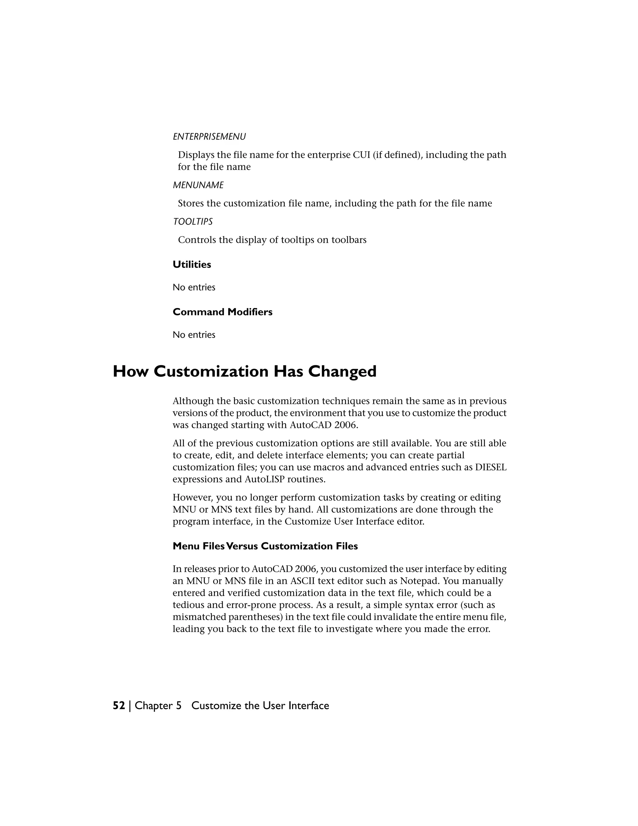


![Following is an example of how the Window menu looked in the legacy menu
file acad.mnu.
Contents of the Window menu in acad.mnu
DescriptionWindow menu
***POP10
**WINDOW
ID_MnWindow [&Window]
ID_DWG_CLOSE [Cl&ose]^C^C_close
ID_WINDOW_CLOSEALL [C&lose All]^C^C_closeall
[--]
ID_WINDOW_CASCADE [&Cascade]^C^C_syswindows;_cascade
ID_WINDOW_TILE_HORZ [Tile &Horizontally]^C^C_syswindows;_hor
ID_WINDOW_TILE_VERT [&Tile Vertically]^C^C_syswindows;_vert
ID_WINDOW_ARRANGE [&Arrange Icons]^C^C_syswindows;_arrange
Compare the menu data above with the same menu data as it is displayed in
the Customize User Interface editor, in the tree view.
For a more detailed comparison, following are examples of the Window menu
properties, Close command properties, Close All command properties, and
the Window shortcut menu that is displayed with the Insert Separator option.
Window menu Properties pane
How Customization Has Changed | 55](https://image.slidesharecdn.com/acadacg-150207145020-conversion-gate02/75/Acad-acg-65-2048.jpg)


![You can also transfer customization information between files. For example,
you can transfer toolbars from a partial CUI file to the main CUI file so that
the program can display the toolbar information.
NOTE Button images may not appear in the program when you transfer a toolbar
or menu from a partial CUI file. If the images are loaded from an image file, those
images must reside in a folder that is defined under Support File Search Path or
Custom Icon Location of the Files tab in the Options dialog box. If the images
come from a third party resource DLL, contact the party who created the resource
DLL.
NOTE The Migrate Custom Settings dialog box can be used to migrate menu
customization from previous releases. To access the Migrate Custom Settings
dialog box, click Start menu (Windows) ➤ All Programs (or Programs) ➤
Autodesk ➤ [Autodesk product name] ➤ Migrate Custom Settings. Future releases
will migrate button images in the folder defined under Custom Icon Location on
the Files tab of the Options dialog box.
In addition, you can move customizations from the main CUI file to partial
CUI files, or from a partial CUI file to another partial CUI file.
If a workspace or toolbar you are transferring contains flyout toolbars with
references to another menu, toolbar, or flyout toolbar that is located in the
source CUI file, the relevant information for that interface element is also
transferred. For example, if you transfer the Draw toolbar, which references
the Insert toolbar, the Insert toolbar is also transferred.
A CUI file keeps track of any customizations you make. Customization data
is tracked and preserved from release to release, so you can load a CUI file in
another version without losing data or modifying existing CUI data.
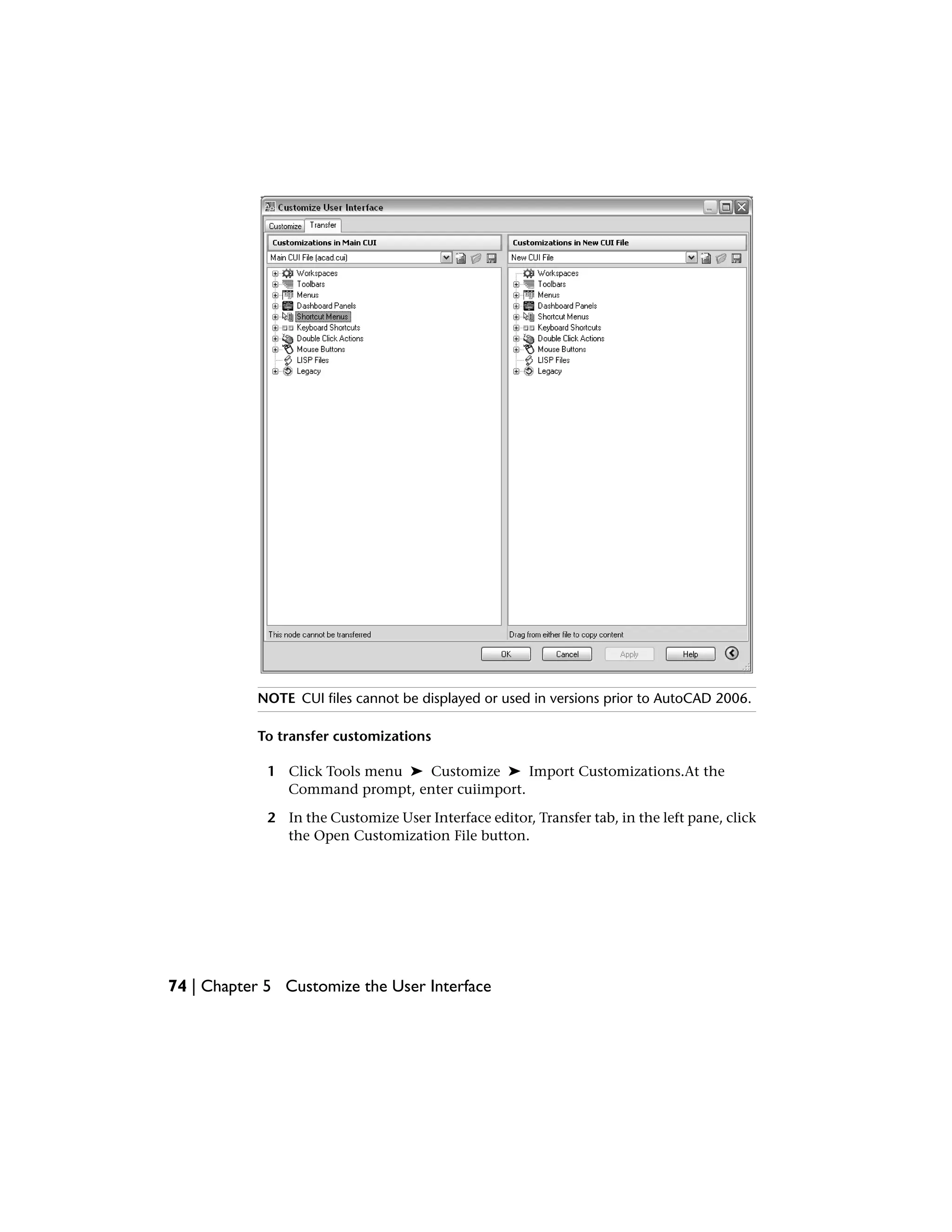
Following is an example of the Customize User Interface editor, Transfer tab.
You use this tab to migrate customizations.
Migrate and Transfer Customizations | 73](https://image.slidesharecdn.com/acadacg-150207145020-conversion-gate02/75/Acad-acg-83-2048.jpg)


![loaded in the product. You can add any commands from this list to toolbars,
menus, and other user interface elements.
When you change properties of a command in the master list or on the tree
view, the properties of the command are changed everywhere that command
is used.
The following table shows the Scale command properties as they appear in
the Properties pane.
Properties for the Scale command on the Modify menu
ExampleDescriptionProperties
pane item
Sca&leString displayed as a menu name or as a tooltip
when you click a toolbar button. The string
Name
must include alphanumeric characters with no
punctuation other than a hyphen (-) or an un-
derscore (_).
Enlarges or reduces
objects proportionally
Status line text. This string is displayed on the
status bar when the cursor hovers over a toolbar
button or menu item.
Descrip-
tion
in the X, Y, and Z direc-
tions: SCALE
$M=$(if,$(eq,$(sub-
str,$(
The command macro. It follows the standard
macro syntax.
Macro
getvar,cmd-
names),1,4),
NOTE When you change the name of a macro,
the name of its corresponding menu item or
toolbar button does not change. You must
change a menu item or toolbar button name
by selecting it in the tree view.
GRIP),_scale,^C^C_scale)
ID_ScaleTag that uniquely identifies a command.Element ID
RCDATA_16_SCALEID string of the small-image resource (16 × 16
bitmap). The string must include alphanumeric
Small Im-
age
characters with no punctuation other than a
hyphen (-) or an underscore (_). It can also be
a user-defined bitmap. Click the ellipses button
[...] to open the Select Image File dialog box.
Customize Commands | 85](https://image.slidesharecdn.com/acadacg-150207145020-conversion-gate02/75/Acad-acg-95-2048.jpg)
![Properties for the Scale command on the Modify menu
ExampleDescriptionProperties
pane item
RCDATA_16_SCALEID string of the large-image resource (32 × 32
bitmap). If the specified bitmap is not 32 × 32,
Large Im-
age
the program scales it to that size. The string
must include alphanumeric characters with no
punctuation other than a hyphen (-) or an un-
derscore (_). It can also be a user-defined bit-
map. Click the ellipses button [...] to open the
Select Image File dialog box
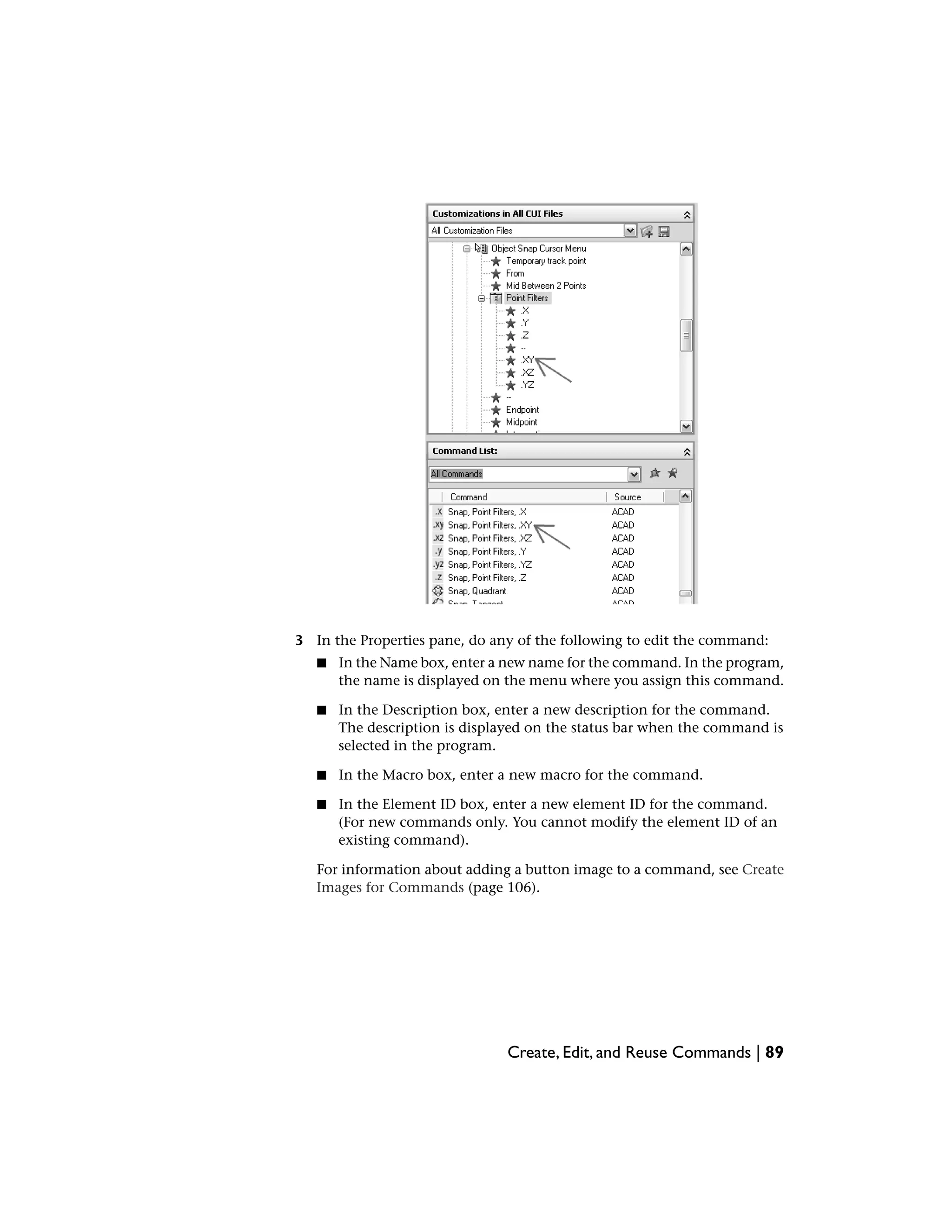
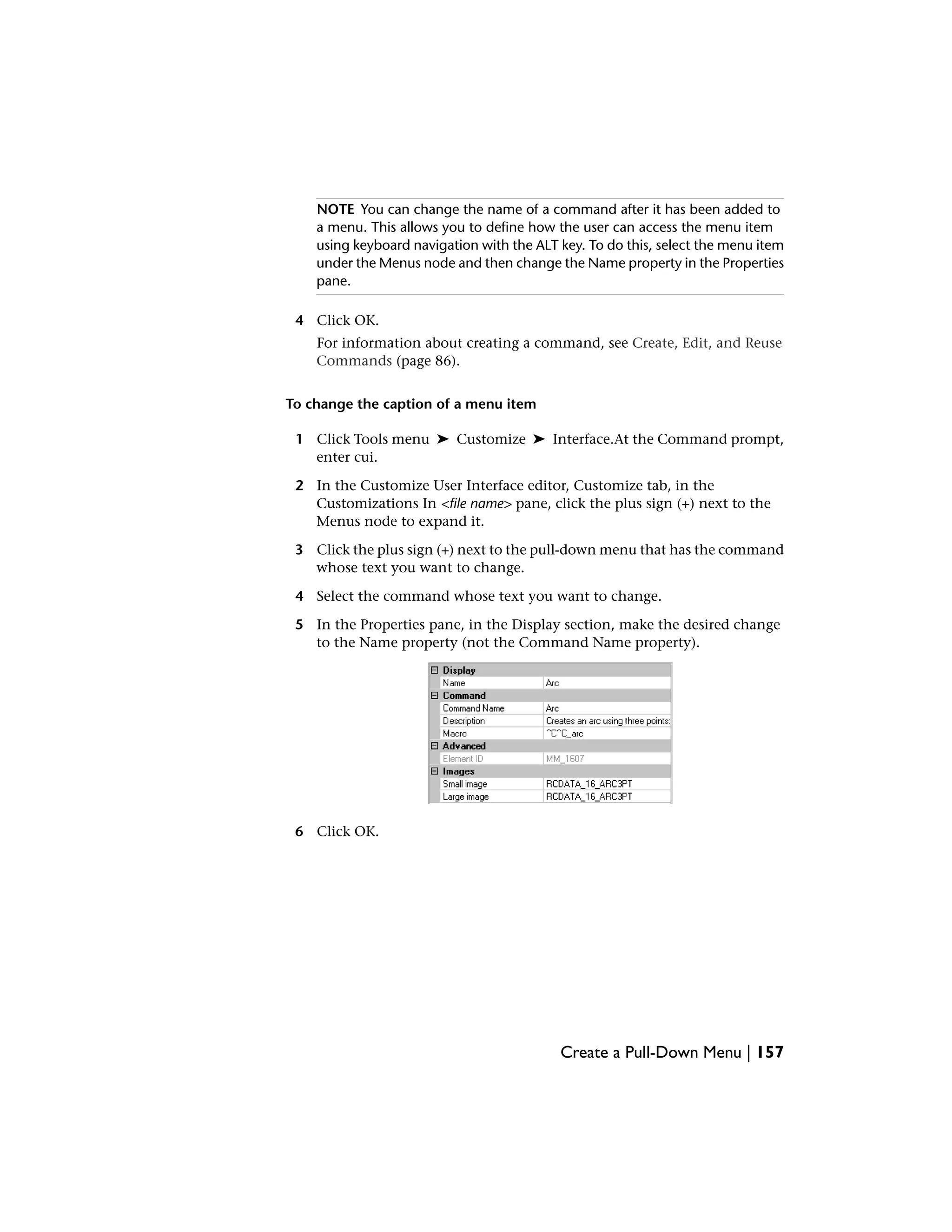
Create, Edit, and Reuse Commands
You can create a new command from scratch, copy an existing command to
create a new command, or edit the properties of an existing command. When
you create or edit a command, the properties you can define are the command
name, description, macro, element ID (for new commands only), and small
or large image.
When you change any properties of a command in the Command List pane,
the command is updated for all interface items that reference that command.
To create a command
1 Click Tools menu ➤ Customize ➤ Interface.At the Command prompt,
enter cui.
2 In the Customize User Interface editor, Customize tab, Command List
pane, click Create a New Command.
86 | Chapter 5 Customize the User Interface](https://image.slidesharecdn.com/acadacg-150207145020-conversion-gate02/75/Acad-acg-96-2048.jpg)


![When you place a space at the end of the macro, AutoCAD processes the
macro as though you had entered a command (circle, for example) and then
pressed the SPACEBAR to complete the command.
Terminate Macros
Some macros require special terminators. Some commands (TEXT, for example)
require you to press ENTER rather than SPACEBAR to terminate the command.
Some commands require more than one space (or ENTER) to complete, but
some text editors cannot create a line with trailing blanks.
Two special conventions resolve these problems.
■ A semicolon (;) in a macro automatically issues ENTER at the command
prompt.
■ If a line ends with a control character, a backslash (), a plus sign (+), or a
semicolon (;), AutoCAD does not add a blank space after it.
An item that ends with a backslash () pauses a macro for user input.
Compare the following macros:
ucs
ucs ;
The first example enters ucs at the command prompt and presses SPACEBAR.
The following prompt is displayed.
Specify origin of UCS or
[Face/NAmed/OBject/Previous/View/World/X/Y/Z/ZAxis] <World>:
The second example enters ucs, presses SPACEBAR, and presses ENTER, which
accepts the default value (World).
Suppress Echoes and Prompts in Macros
Characters in a macro appear in the command window as though you had
typed the characters on the keyboard. They are also displayed in the user
interface element. This display duplication is called “echoing”. You can
suppress the “echoed” displays with the MENUECHO system variable. If echoes
and prompts from item input are turned off, a ^P in the item turns them off.
116 | Chapter 5 Customize the User Interface](https://image.slidesharecdn.com/acadacg-150207145020-conversion-gate02/75/Acad-acg-126-2048.jpg)
![Create Long Macros
You can create a macro of any length, without requiring any special characters
at the end of a line. The Properties pane in the Customize User Interface editor
accepts a macro of any length.
Use Special Control Characters in Macros
You can use special characters, including control characters, in macros. In a
macro, the caret (^) is equivalent to pressing the CTRL key on the keyboard.
You can combine the caret with another character to construct macros that
do such things as turn the grid on and off (^G) or cancel a command (^C).
The macro for the Address command below uses the backslash () to pause
for user input and the semicolon (;) for ENTER.
text .4 0 DRAFT Inc;;;Main St.;;;City, State;
The macro starts the TEXT command, pauses for the user to specify a start
point, and then enters the address on three lines. In the triple semicolon (;;;),
the first semicolon ends the text string, the second repeats TEXT, and the
third accepts the default placement below the previous line.
Macros use the special characters listed in the following table.
Special characters used in macros
DescriptionCharacter
Issues ENTER;
Issues ENTER^M
Issues TAB^I
Enters a space; a blank space between command sequences in a
command is equivalent to pressing the SPACEBAR
[blank space]
Pauses for user input (cannot be used with accelerators)
Allows you to access a built-in AutoCAD command even if it was un-
defined using the UNDEFINE command.
.
Use Special Control Characters in Macros | 117](https://image.slidesharecdn.com/acadacg-150207145020-conversion-gate02/75/Acad-acg-127-2048.jpg)


![Utilities
No entries
Command Modifiers
No entries
Use AutoLISP in Macros
Creating commands that use AutoLISP is a more advanced way to use the
AutoCAD customization feature.
You can use AutoLISP variables and expressions to create macros that perform
complex tasks. To use AutoLISP efficiently in macros, place AutoLISP code in
a separate MNL file. AutoCAD loads the MNL file when it loads a CUI file with
the same name and in the same location.
You can specify additional AutoLISP files to load in the Customize User
Interface editor. Creating commands that use AutoLISP is a more advanced
way to use the AutoCAD customization feature. Carefully study the following
examples and the information in the AutoLISP Reference and the AutoLISP
Developer's Guide. To access the additional help resources, click Help menu ➤
Additional Resources ➤ Developer Help.Experimentation and practice will
help you use this feature effectively.
Call a Macro
To programmatically execute a pull-down menu macro, use the following
syntax:
(menucmd "Gmenugroup.element_ID=|")
The previous syntax works only if the menu macro is part of a menu that is
on the AutoCAD menu bar and is available for use. For more information
about this syntax, see the AutoLISP Reference.
PresetValues
An application that uses block insertion presets could provide commands like
these: [Set WINWID][Set WALLTHK][Insert Window]
Use AutoLISP in Macros | 129](https://image.slidesharecdn.com/acadacg-150207145020-conversion-gate02/75/Acad-acg-139-2048.jpg)

![The following table shows the Standard toolbar properties as they appear in
the Properties pane.
Properties for the Standard toolbar
ExampleDescriptionProperties
pane item
StandardString used as the caption for the toolbar.Name
Standard ToolbarText used to describe the element; does not
appear in the user interface.
Descrip-
tion
ShowSpecifies whether the toolbar is displayed or not
the first time the CUI file is loaded. The values
are Hide or Show.
On By De-
fault
TopSpecifies whether the toolbar is floating or
docked (top, bottom, left, or right) the first time
the CUI file is loaded.
Orienta-
tion
0Specifies the location from the left edge of the
screen when the toolbar appears when it is
Default X
Location
floating, or the location when it is docked. If
docked, a value of 0 indicates the left most
location in a docked area.
0Specifies the location from the top edge of the
screen when the toolbar appears when it is
Default Y
Location
floating, or the location when it is docked. If
docked, a value of 0 indicates the top most
location in a docked area.
1Specifies the number of rows the items on the
toolbar are displayed in when the toolbar is
floating.
Rows
TB_STANDARD,
Standard
Specifies the aliases for the toolbar. Click the
ellipses button [...] to open the Aliases dialog
Aliases
box. Each alias in the CUI file should be unique
132 | Chapter 5 Customize the User Interface](https://image.slidesharecdn.com/acadacg-150207145020-conversion-gate02/75/Acad-acg-142-2048.jpg)

![Properties for the Zoom flyout on the Standard toolbar
ExampleDescriptionProperties
pane item
TB_ZOOMA read-only value used to specify which toolbar
is being referenced to create the flyout.
Source
Toolbar
NoControls whether the last used toolbar button
is set as the current button or not. The possible
values are Yes or No.
Use Own
Button
RCDATA_16_ZOOMID string of the small-image resource (16 × 16
bitmap). The string must include alphanumeric
Small Im-
age
characters with no punctuation other than a
hyphen (-) or an underscore (_). It can also be
a user-defined bitmap. Click the ellipses button
[...] to open the Select Image File dialog box.
RCDATA_16_ZOOMID string of the large-image resource (32 × 32
bitmap). If the specified bitmap is not 32 × 32,
Large Im-
age
the program scales it to that size. The string
must include alphanumeric characters with no
punctuation other than a hyphen (-) or an un-
derscore (_). It can also be a user-defined bit-
map. Click the ellipses button [...] to open the
Select Image File dialog box
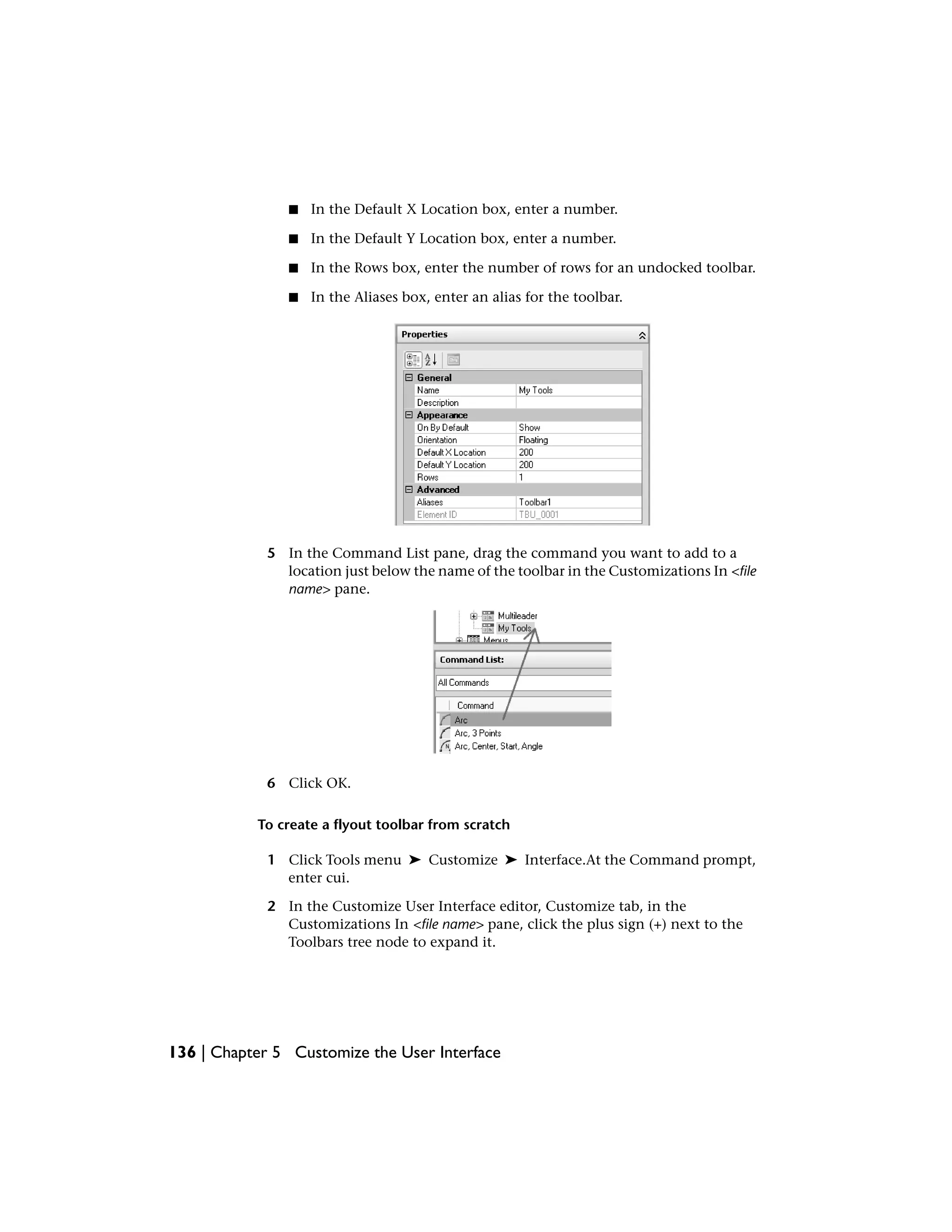
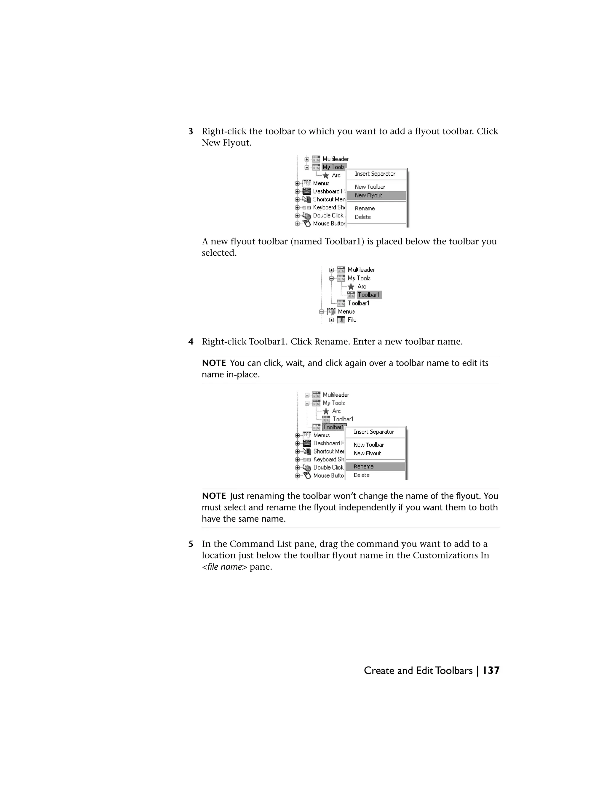
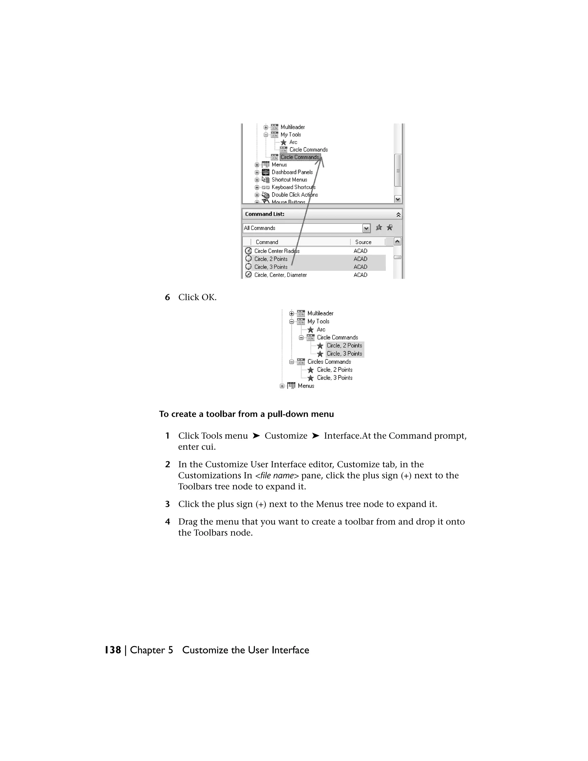
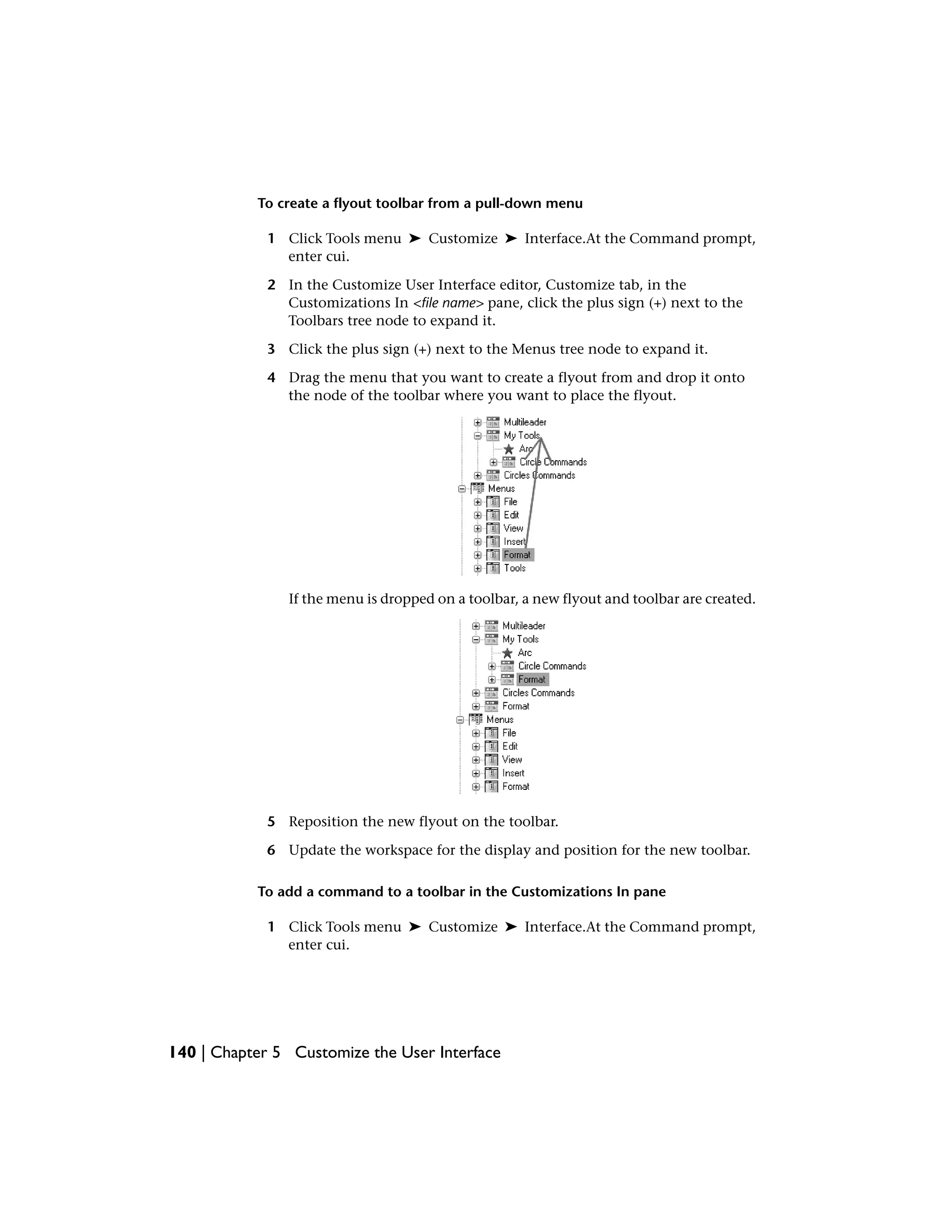
When you create a new toolbar or flyout toolbar, the first task you need to
do is assign a name to it. A new toolbar has no commands or controls assigned
to it. If a toolbar has no commands or controls on it, it is ignored by the
program until you add at least one command or control to it. You can drag
commands and controls onto the new toolbar from existing toolbars or from
the Command List pane. Once a command has been added to the toolbar,
you can change the text that is displayed in the tooltip when the cursor is
paused over top of the button by adjusting the Name property that is displayed
in the Properties pane.
While commands and controls can be added to or removed from a toolbar in
the Customizations In <file name> pane, but they can also be added or removed
using the Toolbar Preview pane. The Toolbar Preview pane allows you to add
and remove commands or controls visually in real-time instead of just using
134 | Chapter 5 Customize the User Interface](https://image.slidesharecdn.com/acadacg-150207145020-conversion-gate02/75/Acad-acg-144-2048.jpg)


![SystemVariables
No entries
Utilities
No entries
Command Modifiers
No entries
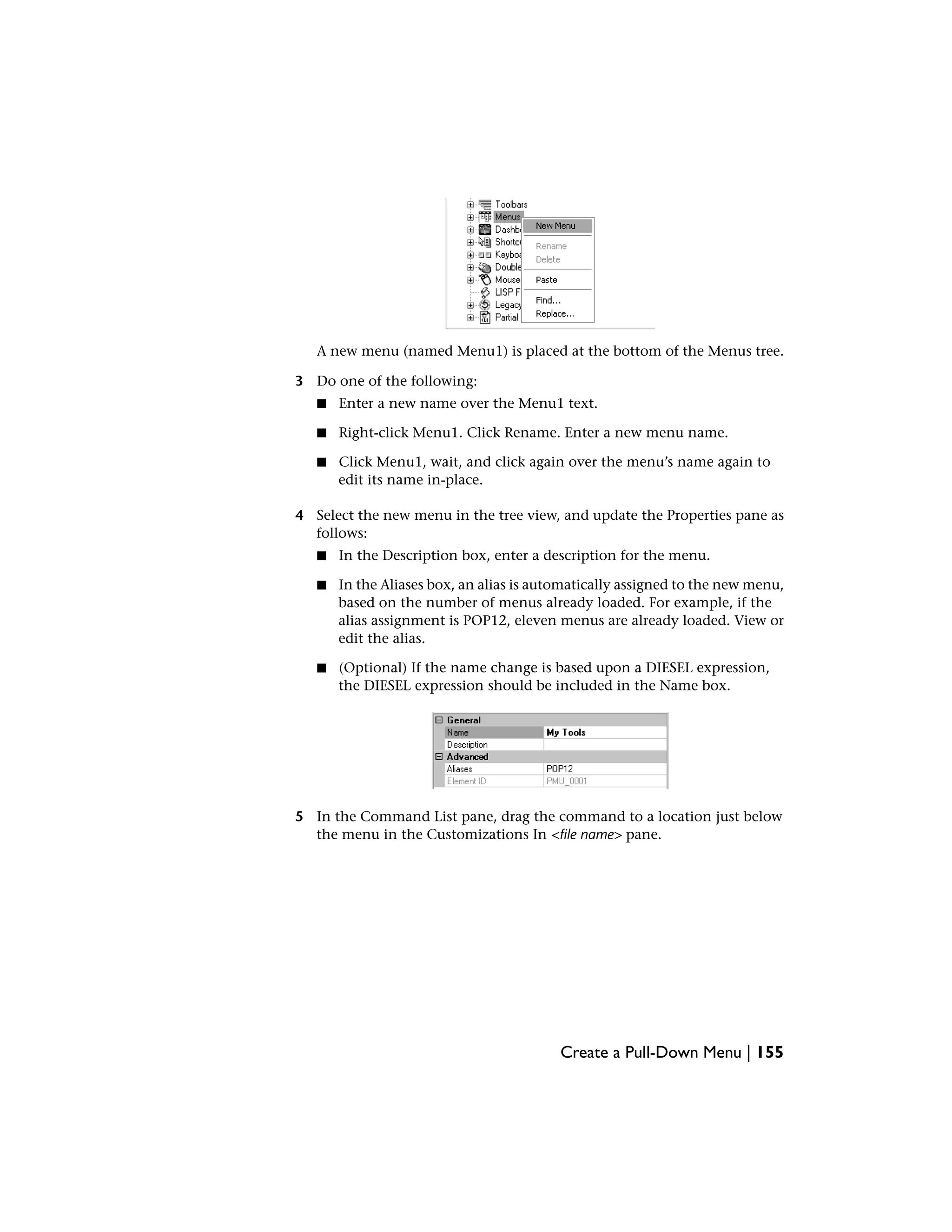
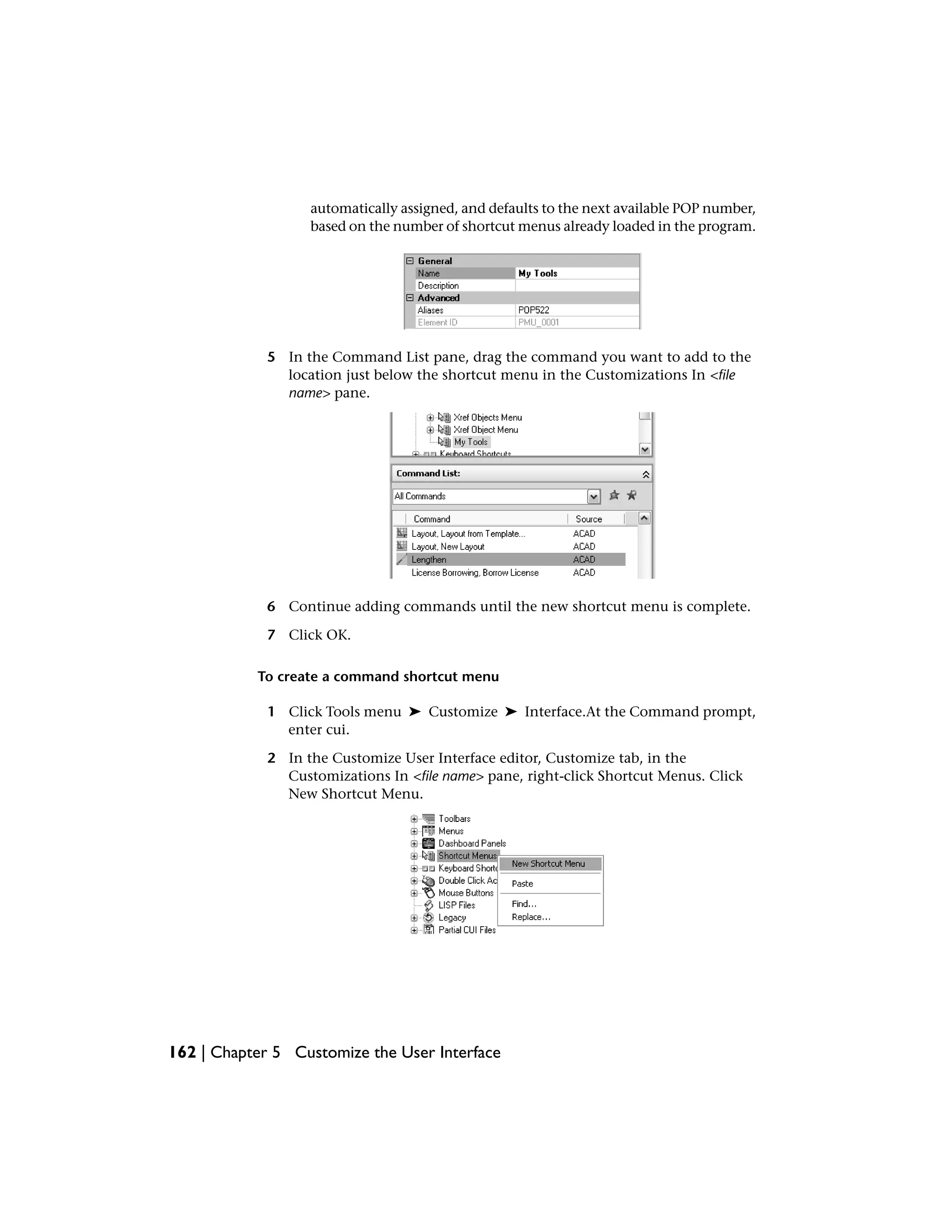
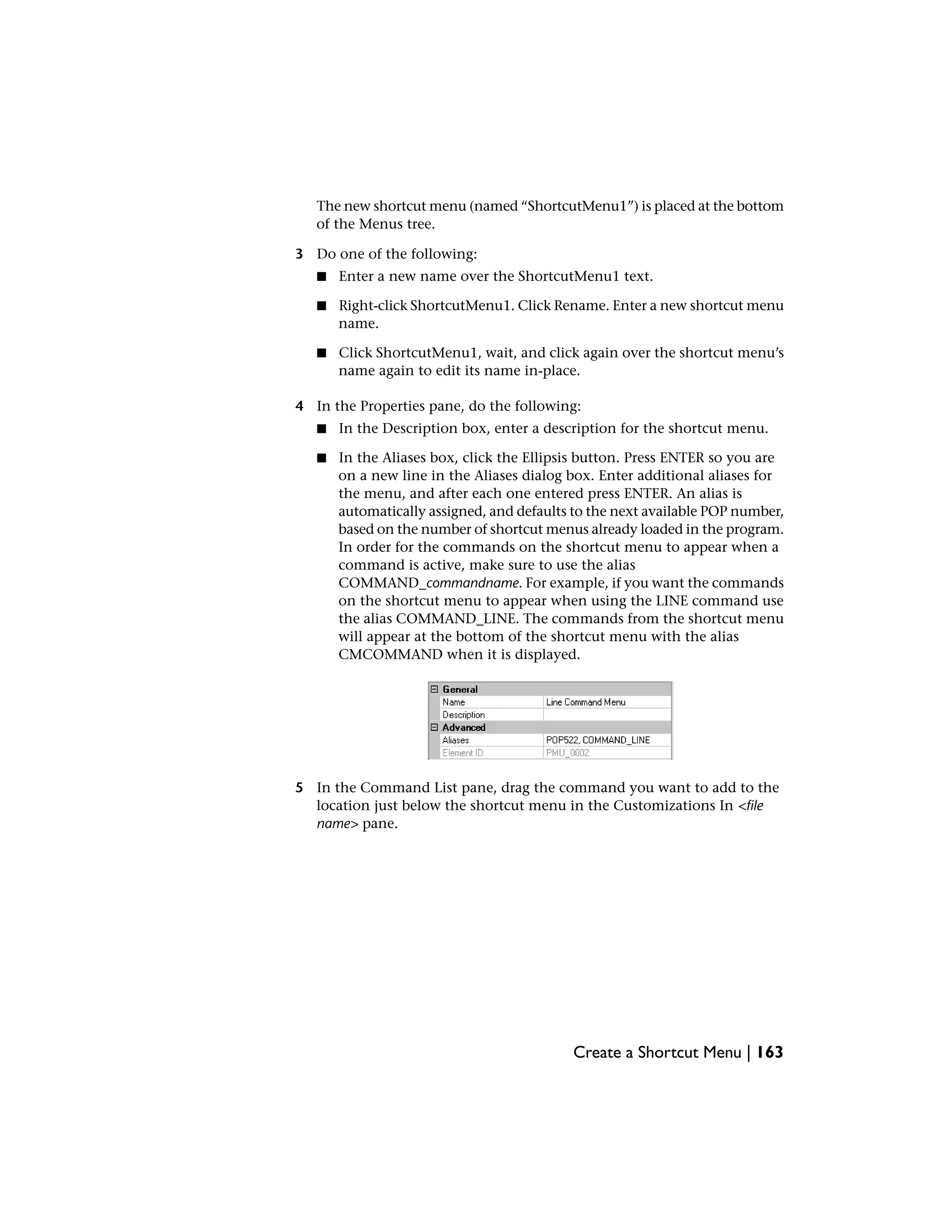
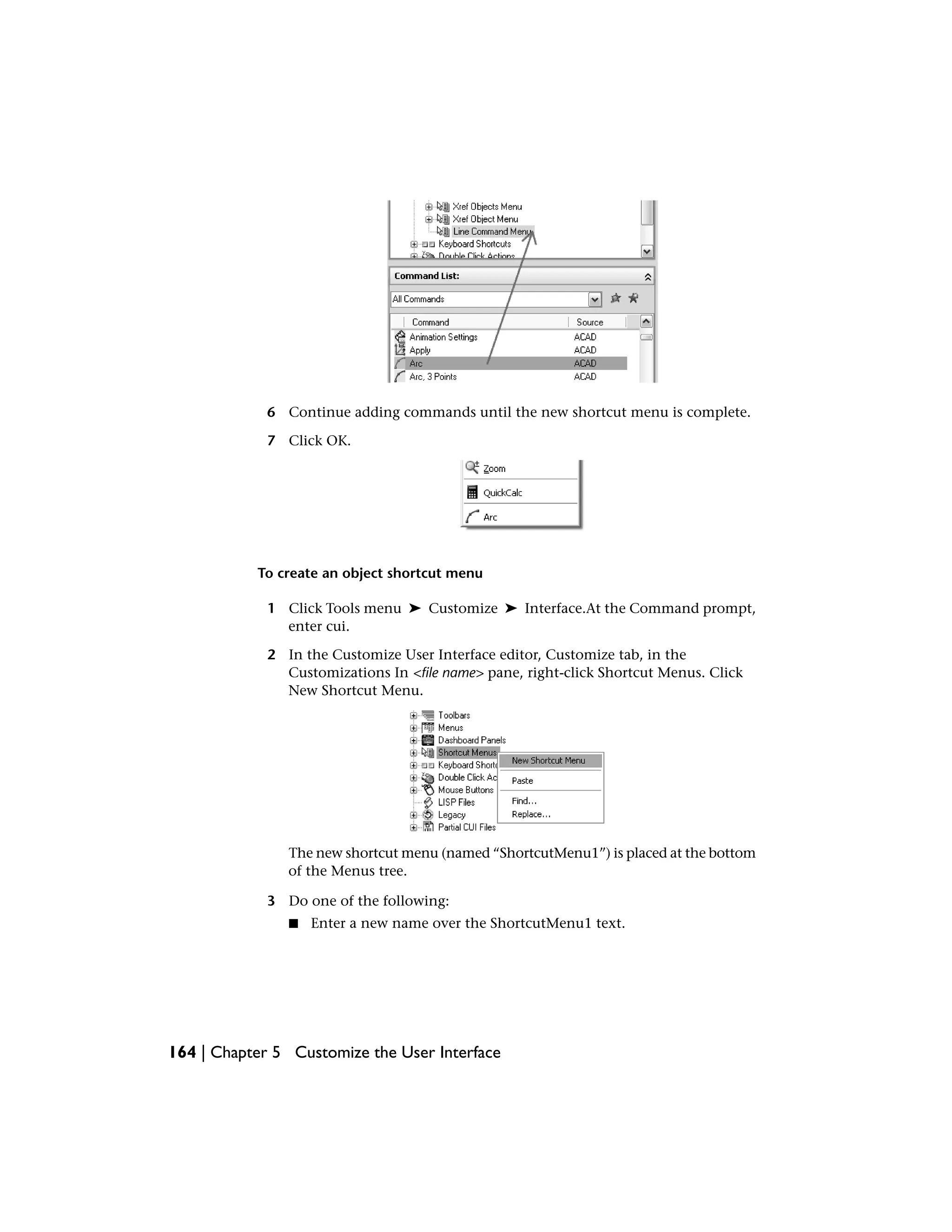
Create Pull-Down and Shortcut Menus
Pull-down menus are displayed as a list under a menu bar. Shortcut menus
(also called context menus) are displayed at or near the crosshairs or cursor
when you right-click in the drawing window, text window, command window,
or in toolbar areas.
A pull-down menu can contain up to 999 commands. A shortcut menu can
contain up to 499 commands. The command limit includes all menus in a
hierarchy. If commands in the menu file exceed these limits (which is unlikely),
the program ignores the extra commands. If a pull-down or shortcut menu is
longer than the available display space, it is truncated to fit. The following
table shows the File menu properties as they appear in the Properties pane.
The properties for a pull-down menu and shortcut menu are identical.
Properties for the File menu
ExampleDescriptionProperties
pane item
&FileString used as the caption of the menu on the
menu bar.
Name
Text used to describe the element; does not
appear in the user interface.
Descrip-
tion
POP1, FILESpecifies the aliases for the menu. Click the el-
lipses button [...] to open the Aliases dialog box.
Aliases
Each alias in the CUI file should be unique and
it is used to reference the menu programatically.
Create Pull-Down and Shortcut Menus | 153](https://image.slidesharecdn.com/acadacg-150207145020-conversion-gate02/75/Acad-acg-163-2048.jpg)


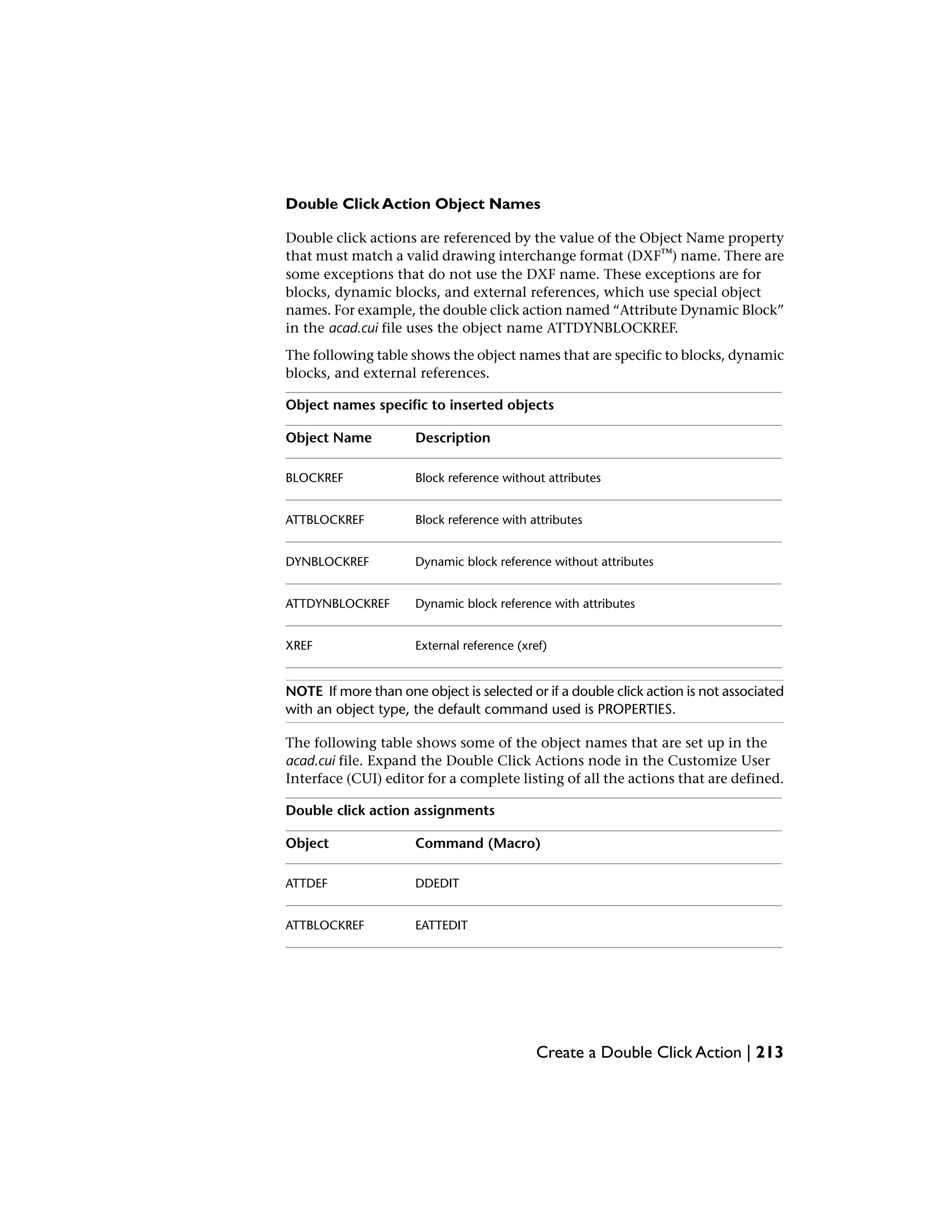
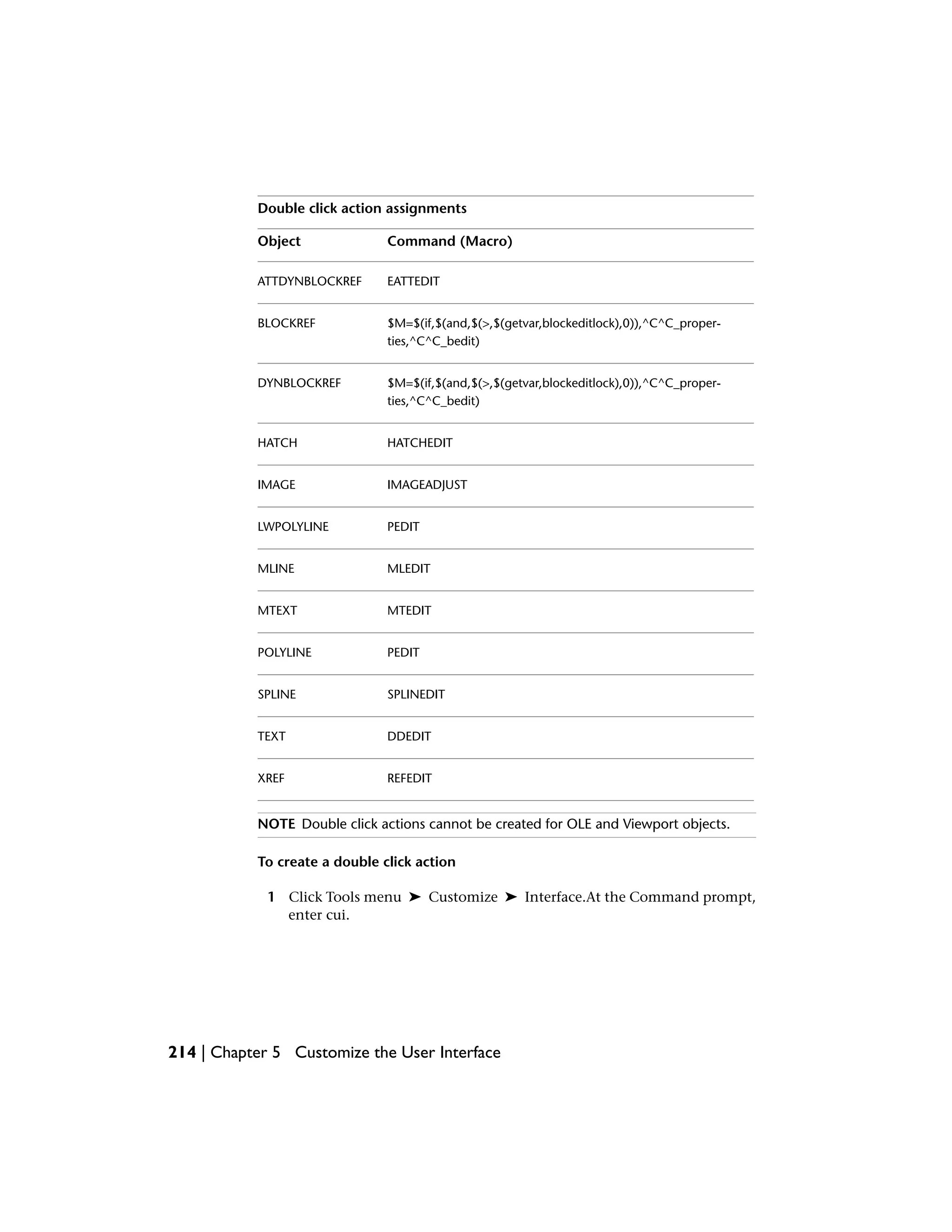
![The object name is the drawing interchange format (DXF™) name of the object
in all cases except for the inserted object. The following table shows the object
names that are specific to blocks, dynamic blocks, and xrefs.
Object names specific to inserted objects
DescriptionObject Name
Block reference without attributesBLOCKREF
Block reference with attributesATTBLOCKREF
Dynamic block reference without attributesDYNBLOCKREF
Dynamic block reference with attributesATTDYNBLOCKREF
External reference (xref)XREF
For example, to support an object-specific shortcut command for one or more
selected block references, you would add the following properties on the
Customize tab, Properties pane of the Customize User Interface editor:
Properties for the Block Reference Objects shortcut menu
ExampleDescriptionProperties
pane item
Block Objects MenuString that is only used in the CUI editor and is
not displayed in the user interface.
Name
Shortcut menu for
block objects
Text used to describe the element; does not
appear in the user interface.
Descrip-
tion
POP512,OB-
JECTS_BLOCKREF
Specifies the aliases for the shortcut menu. Click
the ellipses button [...] to open the Aliases dia-
Aliases
log box. Each alias in the CUI file should be
unique and it is used to reference the shortcut
menu programatically.
PM_0021Tag that uniquely identifies a shortcut menu.Element ID
160 | Chapter 5 Customize the User Interface](https://image.slidesharecdn.com/acadacg-150207145020-conversion-gate02/75/Acad-acg-170-2048.jpg)


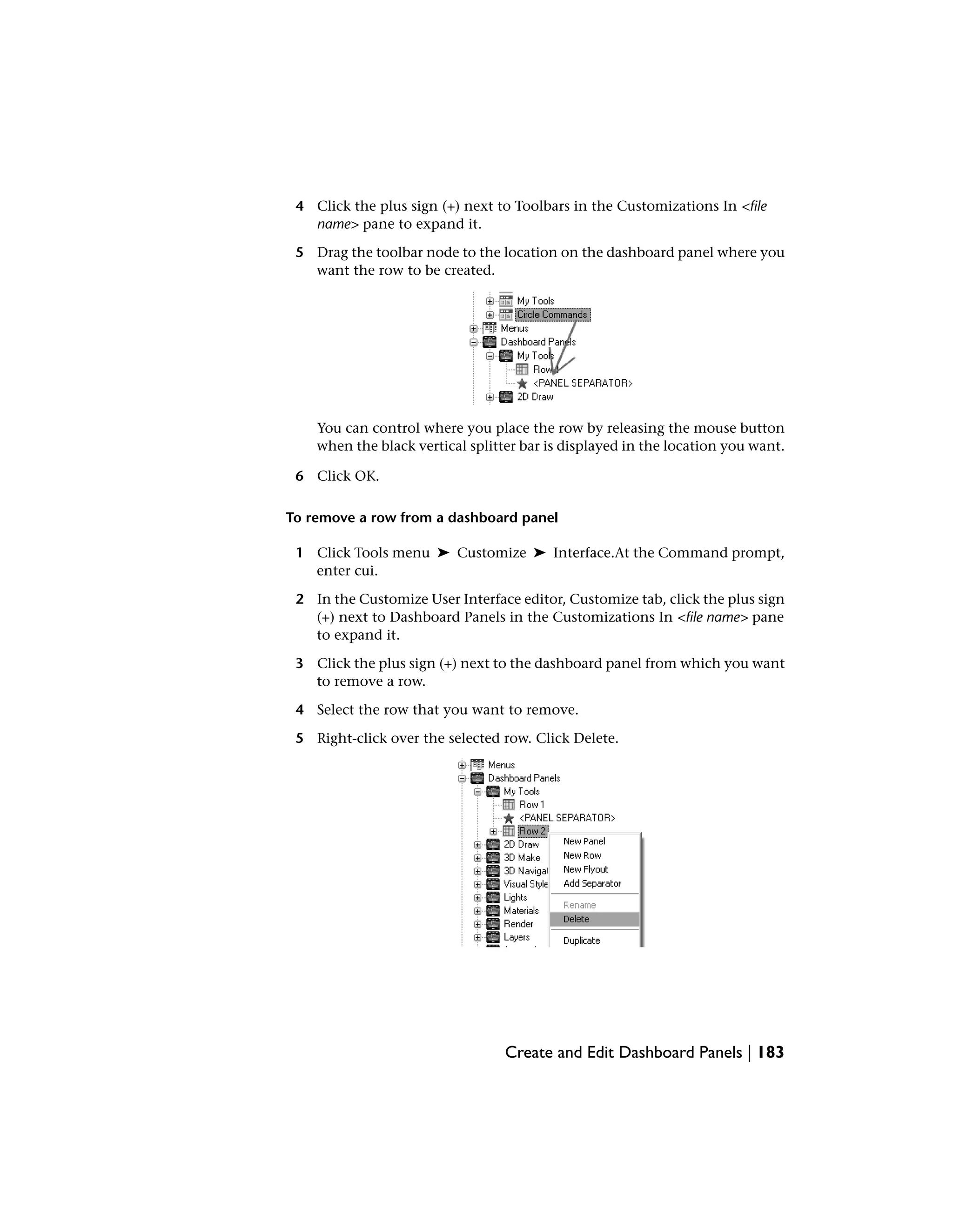
![You can add buttons to a row, remove buttons you use infrequently, and
rearrange buttons. Along with buttons, you can also create flyouts and add
controls.
The following table describes the 2D Draw dashboard panel properties as they
appear in the Properties pane.
Properties for the 2D Draw panel
ExampleDescriptionProperties
pane item
2D DrawTitle for the panel; displayed in the Control
Panels sub-menu when you right-click of the
Dashboard palette.
Name
Text used to describe the element; does not
appear in the user interface.
Descrip-
tion
2D_DrawSpecifies the aliases for the panel. Click the el-
lipses button [...] to open the Aliases dialog box.
Aliases
Each alias in the CUI file should be unique and
it is used to reference the panel programatically.
PNL_0001Tag that uniquely identifies a panel.Element ID
RCDATA_16_DASH_2D_MAKE_MODI-
FY
ID string of the small-image resource (16 × 16
bitmap). The string must include alphanumeric
Small Im-
age
characters with no punctuation other than a
hyphen (-) or an underscore (_). It can also be
a user-defined bitmap. Click the ellipses button
[...] to open the Select Image File dialog box.
RCDATA_16_DASH_2D_MAKE_MODI-
FY
ID string of the large-image resource (32 × 32
bitmap). If the specified bitmap is not 32 × 32,
Large Im-
age
the program scales it to that size. The string
must include alphanumeric characters with no
punctuation other than a hyphen (-) or an un-
derscore (_). It can also be a user-defined bit-
map. Click the ellipses button [...] to open the
Select Image File dialog box.
Create and Edit Dashboard Panels | 177](https://image.slidesharecdn.com/acadacg-150207145020-conversion-gate02/75/Acad-acg-187-2048.jpg)
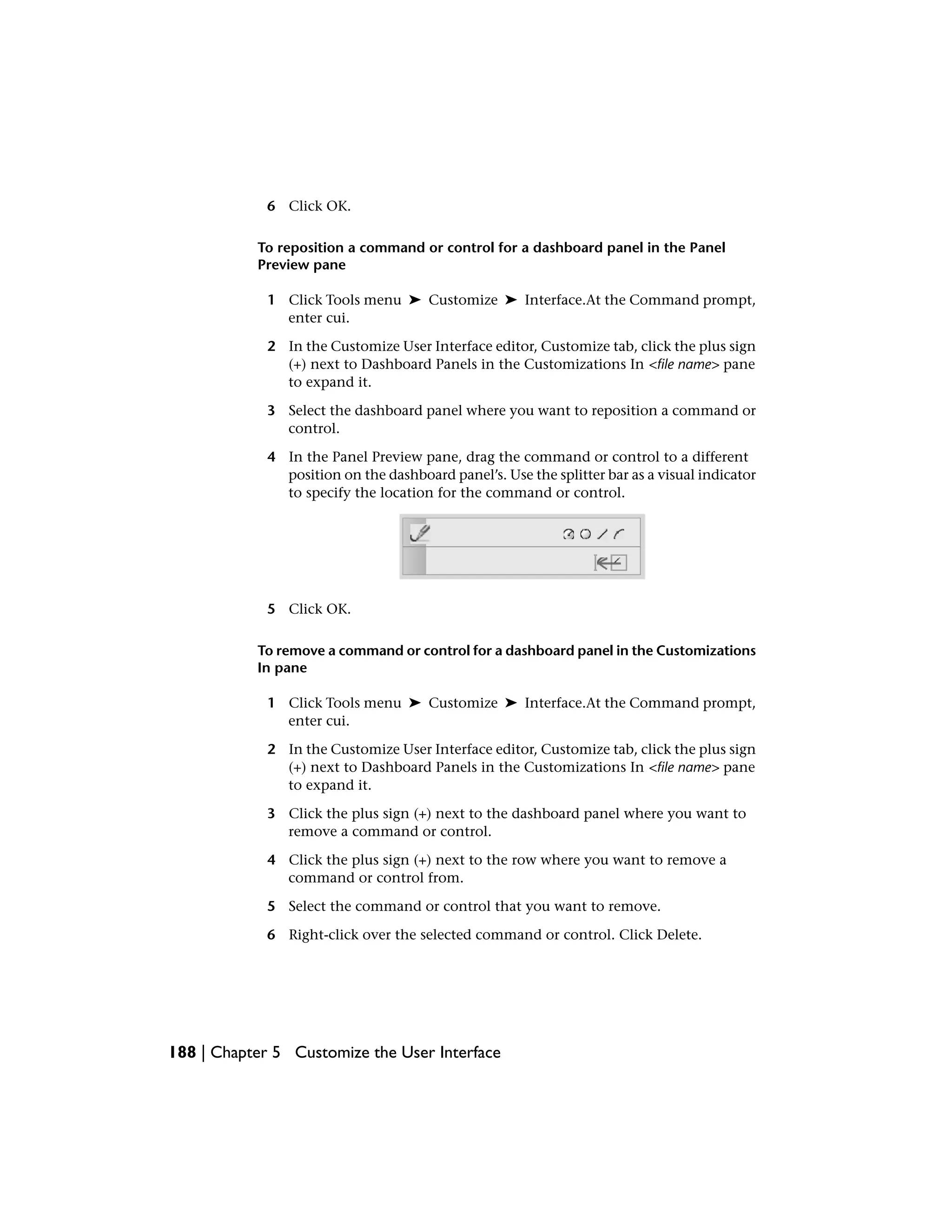
![A row, similar to a toolbar, controls the order and position of tools on a
dashboard panel. Rows run horizontally on a dashboard panel. If all the tools
in a row cannot be displayed at once on the Dashboard palette, a small black
triangle is displayed on the right side of the row so you can access the
additional commands in the row via a flyout.
The following table describes the properties for Row 1 of the 2D Draw
dashboard panel as they appear in the Properties pane.
Properties for Row 1 of the 2D Draw panel
ExampleDescriptionProperties
pane item
DrawLogical name for the section of a panel; does
not appear in the user interface.
Name
Draw ToolbarText used to describe the element; does not
appear in the user interface.
Descrip-
tion
2Number of rows that are in a panel section. A
panel section is defined by the rows that are
Row
s
above or below the <PANEL SEPARATOR> node
of a panel.
TPL_0001Specifies the aliases for the panel section. Click
the ellipses button [...] to open the Aliases dia-
Aliases
log box. Each alias in the CUI file should be
unique and it is used to reference the panel
section programatically.
TPL_0001Tag that uniquely identifies a panel section.Element ID
Dashboard panels, like toolbars, can contain flyouts that hold a number of
buttons and separators to help organize similar tools. A dashboard panel flyout
is created in a slightly different way from that of a flyout on a toolbar. Instead
of the flyout referencing a toolbar; it is created like a sub-menu on a pull-down
menu, but it has the same properties as a toolbar flyout.
178 | Chapter 5 Customize the User Interface](https://image.slidesharecdn.com/acadacg-150207145020-conversion-gate02/75/Acad-acg-188-2048.jpg)
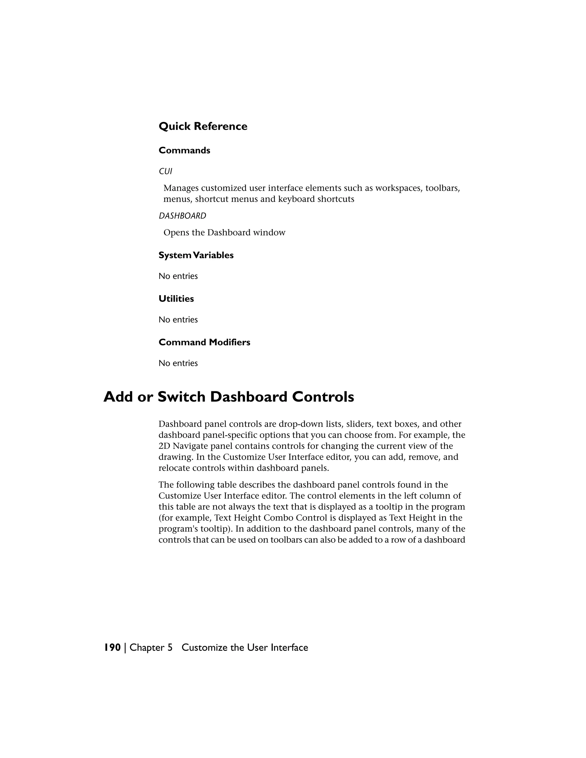
![The following table describes the properties for the Block flyout of Row 1 on
the 2D Draw dashboard panel as they appear in the Properties pane.
Properties for Block flyout on Row 1 of the 2D Draw panel
ExampleDescriptionProperties
pane item
BlockLogical name for the flyout; does not appear in
the user interface.
Name
Text used to describe the element; does not
appear in the user interface.
Descrip-
tion
NoControls whether the last used button is set as
the current button or not. The possible values
are Yes or No.
Use Own
Icon
RCDATA_16_BLOCKID string of the small-image resource (16 × 16
bitmap). The string must include alphanumeric
Small Im-
age
characters with no punctuation other than a
hyphen (-) or an underscore (_). It can also be
a user-defined bitmap. Click the ellipses button
[...] to open the Select Image File dialog box.
RCDATA_16_BLOCKID string of the large-image resource (32 × 32
bitmap). If the specified bitmap is not 32 × 32,
Large Im-
age
the program scales it to that size. The string
must include alphanumeric characters with no
punctuation other than a hyphen (-) or an un-
derscore (_). It can also be a user-defined bit-
map. Click the ellipses button [...] to open the
Select Image File dialog box.
When you create a new dashboard panel, row, or dashboard flyout, the first
task you need to do is assign a name to it. When you create a new dashboard
panel a single row is created, the <PANEL SEPARATOR> is added, and no
commands or controls are assigned. You can drag commands and controls
onto a row of the new dashboard panel from existing dashboard panels or
from the Command List pane. Once a command has been added to the
dashboard panel, you can change the tooltip text by changing the Name
property in the Properties pane.
Create and Edit Dashboard Panels | 179](https://image.slidesharecdn.com/acadacg-150207145020-conversion-gate02/75/Acad-acg-189-2048.jpg)


![Properties for the Save shortcut key
ExampleDescriptionProperties
pane item
CTRL+SSpecifies the keystroke combination that is used
to execute the macro. Click the ellipses button
[...] to open the Shortcut Keys dialog box.
Keys
ID_SaveTag that uniquely identifies a command.Element ID
Temporary override keys are keys that temporarily turn on or turn off one of
the drawing aids that are set in the Drafting Settings dialog box (for example,
Ortho mode, object snaps, or Polar mode). The following table shows the
Object Snap Override: Endpoint temporary override key properties as they
appear in the Properties pane.
Properties for the Object Snap Override : Endpoint Temporary Override Key
ExampleDescriptionProperties
pane item
Object Snap Override : EndpointString that is only used in the CUI
editor and is not displayed in the
user interface.
Name
Object Snap Override : EndpointText used to describe the ele-
ment; does not appear in the
user interface.
Descrip-
tion
SHIFT+ESpecifies the keystroke combina-
tion that is used to execute the
Keys
temporary override. Click the el-
lipses button [...] to open the
Shortcut Keys dialog box.
^P'_.osmode 1 $(if,$(eq,$(getvar,osnapover-
ride),0),'_.osnapoverride 1)
Specifies the macro that should
be executed when the keystroke
Macro1
(Key
Down) combination is held down by the
user.
198 | Chapter 5 Customize the User Interface](https://image.slidesharecdn.com/acadacg-150207145020-conversion-gate02/75/Acad-acg-208-2048.jpg)


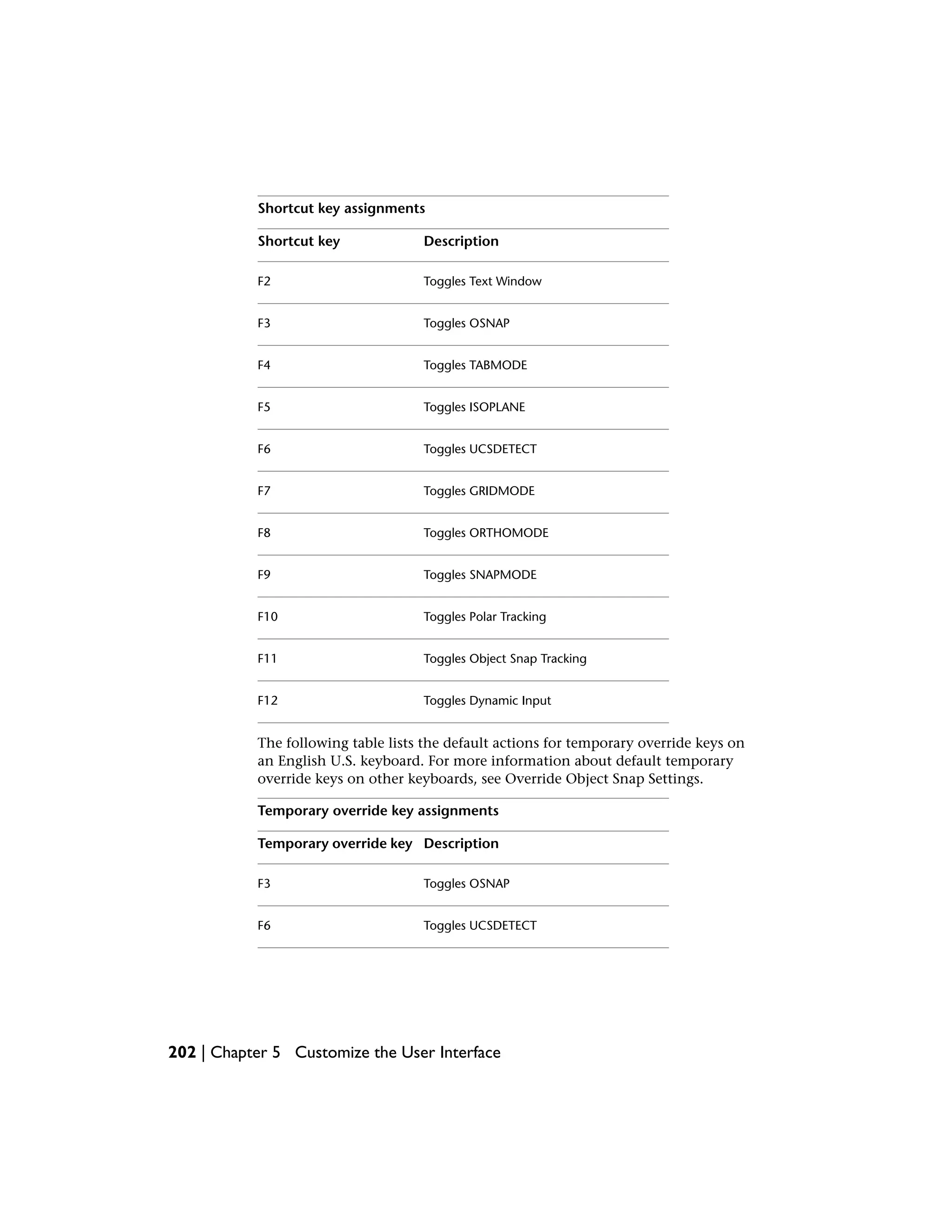
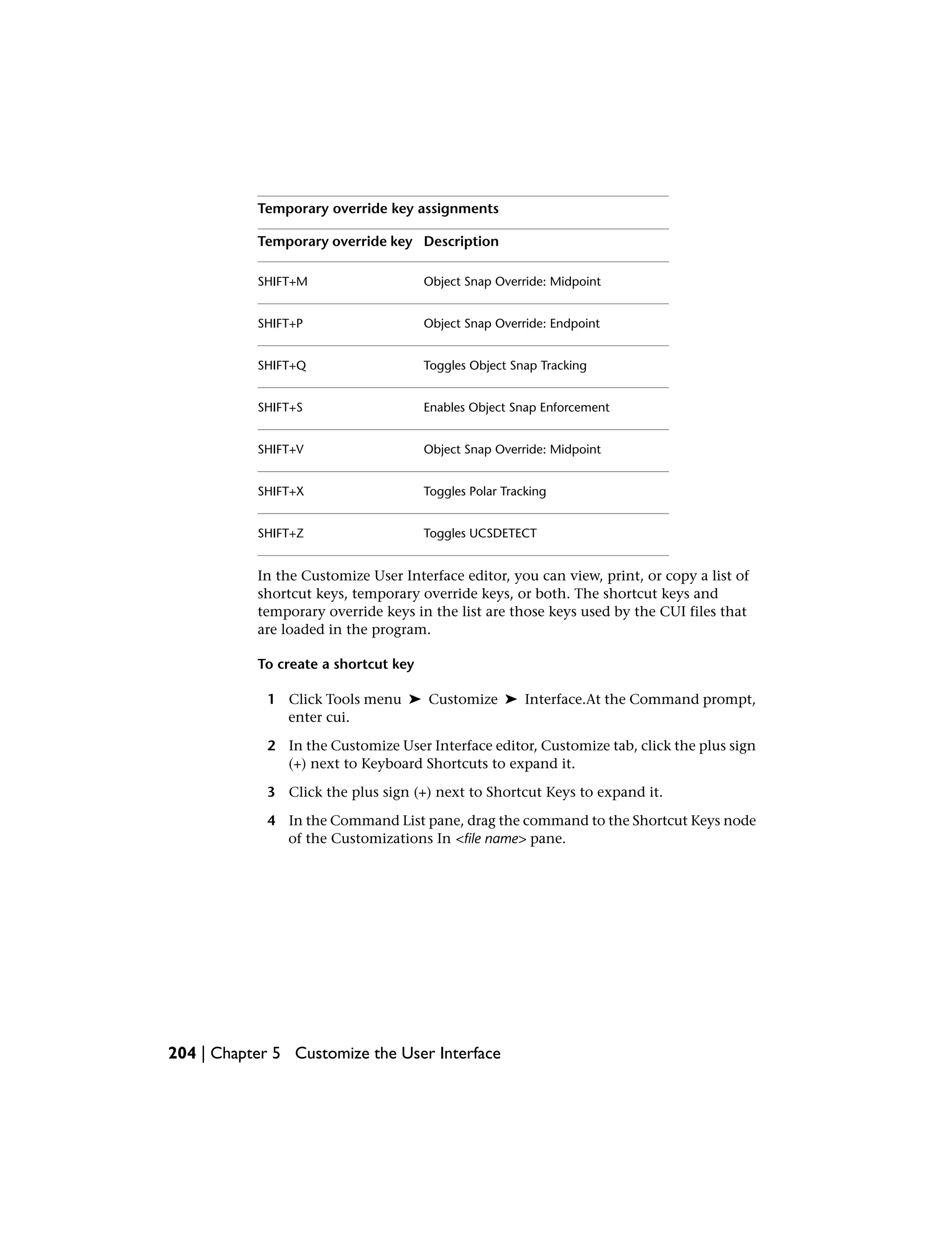
![Temporary override key assignments
DescriptionTemporary override key
Toggles ORTHOMODEF8
Toggles SNAPMODEF9
Toggles Polar TrackingF10
Toggles Object Snap TrackingF11
Toggles Dynamic InputF12
Toggles ORTHOMODESHIFT
Toggles SNAPMODESHIFT+’
Object Snap Override: CenterSHIFT+,
Toggles Polar TrackingSHIFT+.
Toggles UCSDETECTSHIFT+/
Enables Object Snap EnforcementSHIFT+;
Toggles Object Snap TrackingSHIFT+]
Toggles OSNAPSHIFT+A
Object Snap Override: CenterSHIFT+C
Disable All Snapping and TrackingSHIFT+D
Object Snap Override: EndpointSHIFT+E
Disable All Snapping and TrackingSHIFT+L
Add Shortcut Keys and Temporary Override Keys | 203](https://image.slidesharecdn.com/acadacg-150207145020-conversion-gate02/75/Acad-acg-213-2048.jpg)
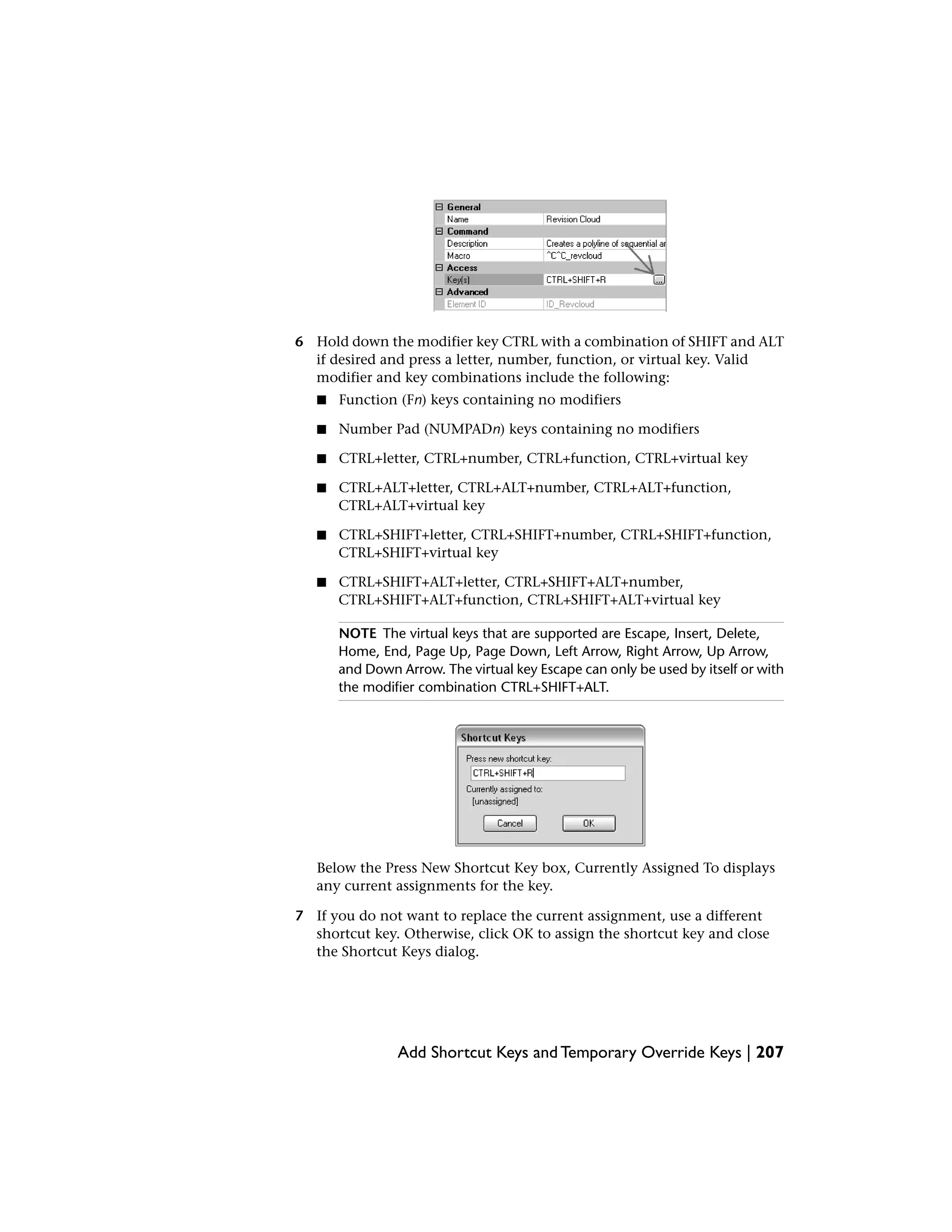
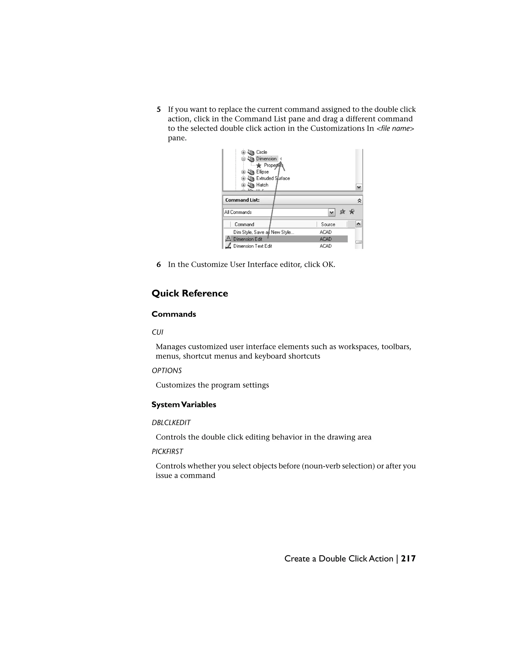
![In the Properties pane, the properties for the new shortcut key you created
are displayed.
5 In the Key(s) box, click the [...] button to open the Shortcut Keys dialog
box.
6 In the Shortcut Keys dialog box, click in the Press New Shortcut Key box
to ensure the box has focus.
7 Hold down the modifier key CTRL with a combination of SHIFT and ALT
if desired and press a letter, number, function, or virtual key. Valid
modifier and key combinations include the following:
■ Function (Fn) keys containing no modifiers
■ Number Pad (NUMPADn) keys containing no modifiers
■ CTRL+letter, CTRL+number, CTRL+function, CTRL+virtual key
Add Shortcut Keys and Temporary Override Keys | 205](https://image.slidesharecdn.com/acadacg-150207145020-conversion-gate02/75/Acad-acg-215-2048.jpg)
![■ CTRL+ALT+letter, CTRL+ALT+number, CTRL+ALT+function,
CTRL+ALT+virtual key
■ CTRL+SHIFT+letter, CTRL+SHIFT+number, CTRL+SHIFT+function,
CTRL+SHIFT+virtual key
■ CTRL+SHIFT+ALT+letter, CTRL+SHIFT+ALT+number,
CTRL+SHIFT+ALT+function, CTRL+SHIFT+ALT+virtual key
NOTE The virtual keys that are supported are Escape, Insert, Delete,
Home, End, Page Up, Page Down, Left Arrow, Right Arrow, Up Arrow,
and Down Arrow. The virtual key Escape can only be used by itself or with
the modifier combination CTRL+SHIFT+ALT.
Under the Press New Shortcut Key box, Currently Assigned To displays
any current assignments for the shortcut key.
8 If you do not want to replace the current assignment, use a different
shortcut key. Otherwise, click OK to assign the shortcut key and close
the Shortcut Keys dialog.
9 In the Customize User Interface editor, click OK.
To modify a shortcut key
1 Click Tools menu ➤ Customize ➤ Interface.At the Command prompt,
enter cui.
2 In the Customize User Interface editor, Customize tab, click the plus sign
(+) next to Keyboard Shortcuts to expand it.
3 Click the plus sign (+) next to Shortcut Keys to expand it.
4 Click a shortcut key.
In the Properties pane, the properties for the shortcut key you selected
are displayed.
5 In the Key(s) box, click the [...] button to open the Shortcut Keys dialog
box.
206 | Chapter 5 Customize the User Interface](https://image.slidesharecdn.com/acadacg-150207145020-conversion-gate02/75/Acad-acg-216-2048.jpg)
![8 In the Customize User Interface editor, click OK.
To create a temporary override key
1 Click Tools menu ➤ Customize ➤ Interface.At the Command prompt,
enter cui.
2 In the Customize User Interface editor, Customize tab, click the plus sign
(+) next to Keyboard Shortcuts to expand it.
3 In the Customizations In <file name> pane, right-click Temporary Override
Keys. Click New Temporary Override.
A new temporary override (named TemporaryOverride1) is placed at the
bottom of the Temporary Override Keys tree.
4 Do one of the following:
■ Enter a new name over the TemporaryOverride1 text.
■ Right-click TemporaryOverride1. Click Rename. Enter a new temporary
override name.
■ Click TemporaryOverride1, wait, and click again over the temporary
override’s name again to edit its name in-place.
5 Select the new temporary override in the tree view, and update the
Properties pane:
■ In the Description box, enter a description for the temporary override
key.
■ In the Key(s) box, click the [...] button to open the Shortcut Keys
dialog box. In the Shortcut Keys dialog box, click in the Press New
Shortcut Key box to ensure the box has focus, and press a key. Valid
modifier keys include function (Fn keys) with no modifiers,
SHIFT+letter, or SHIFT+number key.
208 | Chapter 5 Customize the User Interface](https://image.slidesharecdn.com/acadacg-150207145020-conversion-gate02/75/Acad-acg-218-2048.jpg)
![■ In the Macro 1 (Key Down) box, enter a macro to be executed when
the temporary override key is pressed. When no value is assigned, the
default macro is ^c^c.
■ In the Macro 2 (Key Up) box, enter a macro to be executed when the
temporary override key is released. When no value is defined, key up
restores the application to its previous state (before the temporary
override was executed).
NOTE For information about creating a macro, see Create Macros (page
114).
To modify a temporary override key
1 Click Tools menu ➤ Customize ➤ Interface.At the Command prompt,
enter cui.
2 In the Customize User Interface editor, Customize tab, click the plus sign
(+) next to Keyboard Shortcuts to expand it.
3 Click the plus sign (+) next to Temporary Override Keys to expand it.
4 In the Customizations In <file name> pane, click the temporary override
key you want to modify.
5 Update the Properties pane as necessary:
■ In the Description box, enter a description for the temporary override
key.
■ In the Key(s) box, click the [...] button to open the Shortcut Keys
dialog box. In the Shortcut Keys dialog box, click in the Press New
Shortcut Key box to ensure the box has focus, and press a key. Under
the Press New Shortcut Key box, Currently Assigned To displays any
current assignments for the key. If a key you select is not already
assigned, click OK.
Add Shortcut Keys and Temporary Override Keys | 209](https://image.slidesharecdn.com/acadacg-150207145020-conversion-gate02/75/Acad-acg-219-2048.jpg)


![Utilities
No entries
Command Modifiers
No entries
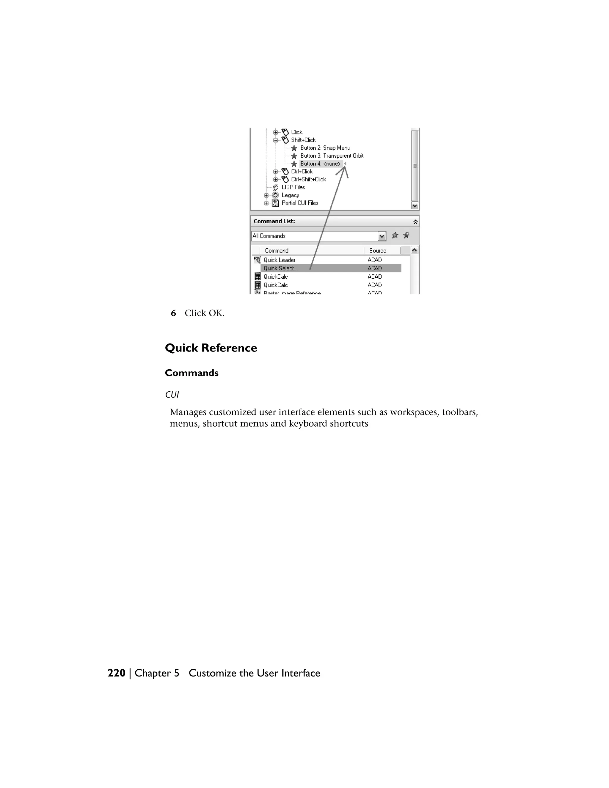
Customize Mouse Buttons
You can change the standard behavior of pointing devices in the program.
Mouse buttons define how a Windows system pointing device functions. You
can customize the behavior of a mouse or other pointing device in the
Customize User Interface editor. If a pointing device has more than two
buttons, you can change the behavior of the second and third buttons. The
first button on any pointing device cannot be changed in the Customize User
Interface editor.
By using the SHIFT and CTRL keys, you can create a number of combinations
to suit your needs. Your pointing device can recognize as many commands
as it has assignable buttons. The Mouse Buttons section of the tree node is
organized by keyboard combination such as Click, SHIFT+Click, CTRL+Click,
and CTRL+SHIFT+Click. The tablet buttons are numbered sequentially. Drag
a command to assign the command to a mouse button. Create additional
buttons by dragging commands to a Click node.
The following table shows the Click mouse button properties as they appear
in the Properties pane.
Properties for the Click mouse button
ExampleDescriptionProperties
pane item
AUX1Specifies the aliases for the mouse button. Click
the ellipses button [...] to open the Aliases dia-
Aliases
log box. Each alias in the CUI file should be
unique and it is used to reference the mouse
button programatically.
218 | Chapter 5 Customize the User Interface](https://image.slidesharecdn.com/acadacg-150207145020-conversion-gate02/75/Acad-acg-228-2048.jpg)

![For example, if you configure a menu area for five columns and four rows,
the command on the line immediately following the Row label corresponds
to the left-most selection box in the top row. The program can recognize up
to 32,766 commands in each tablet section, which should be more than
enough for any tablet menu.
You can add your own macros to the Macros cell in the Properties pane. The
command labels in this area correspond to the 225 boxes at the top of your
tablet template (rows A through I and columns 1 through 25). You can add a
macro using standard command syntax. The following table shows the Click
mouse button properties as they appear in the Properties pane.
Properties for the Tablet Menu 1
ExampleDescriptionProperties
pane item
TABLET1, TABLET1STDSpecifies the aliases for the tablet menu. Click
the ellipses button [...] to open the Aliases dia-
Aliases
log box. Each alias in the CUI file should be
unique and it is used to reference the tablet
menu programatically.
9Number of rows that can be customized for the
tablet menu.
Rows
25Number of columns that can be customized for
the tablet menu.
Columns
To define rows and columns in a tablet menu
1 Click Tools menu ➤ Customize ➤ Interface.At the Command prompt,
enter cui.
2 In the Customize User Interface editor, Customize tab, in the
Customizations In <file name> pane, click the plus sign (+) next to Legacy
to expand the list.
3 Click the plus sign (+) next to Tablet Menus to expand the list.
4 Click the plus sign (+) next to a tablet menu to expand the list.
5 Click the row that you want to define.
6 In the Command List pane, locate the command you want to add.
222 | Chapter 5 Customize the User Interface](https://image.slidesharecdn.com/acadacg-150207145020-conversion-gate02/75/Acad-acg-232-2048.jpg)


![Edit Screen Menu Properties
You can modify screen menu properties, as shown in the following table.
Properties for screen menus
ExampleDescriptionProperties
pane item
SCREENSets the name of the menu.Name
Text that describes the element; does
not appear in the user interface.
Description
1Sets the start line of the screen menu
submenu.
Start line
27Sets the number of lines in a screen
submenu.
Number of lines
SCREEN, SSpecifies the alias for the screen
menu. “Collection” is displayed if
Aliases
multiple definitions are assigned to
this alias. Click the ellipses button [...]
to open the Aliases dialog box.
For the AutoCAD screen menu, which is the root menu, the aliases in the
Aliases box are Screen (which represents the beginning of the screen menu)
and S (which represents the submenu section label). Line assignments for
other menus define the order of the options on the menu. For example, the
File menu on Line 3 in the tree view of the AutoCAD screen menu is in the
third position on the AutoCAD screen menu.
The submenu names in the tree view correspond to the name of the first
submenu item. For example, the New submenu contains commands such as
OPEN, QSAVE, and SAVEAS—in addition to NEW. The Aliases box for these
submenus defines which menu contains them and the Start Line box specifies
their position on that menu. The New submenu is displayed in position 3 on
the File screen menu. Therefore, in the Properties pane, its start line is 3. When
you double-click Aliases to display the Aliases dialog box, you can see that its
menu assignment is 01_FILE.
226 | Chapter 5 Customize the User Interface](https://image.slidesharecdn.com/acadacg-150207145020-conversion-gate02/75/Acad-acg-236-2048.jpg)


![You define an image tile menu in the Customize User Interface editor. The
following table shows the 3D Objects image tile menu properties as they appear
in the Properties pane.
Properties for the 3D Object image tile menu
ExampleDescriptionProperties
pane item
3D ObjectsString that is used only in the CUI editor and is
not displayed in the user interface.
Name
Text that describes the element and does not
appear in the user interface.
Descrip-
tion
image, image_3DOb-
jects
Specifies the aliases for the image tile menu.
Click the ellipses button [...] to open the Aliases
Aliases
dialog box. Each alias in the CUI file should be
unique and it is used to reference the image file
menu programatically.
The following table shows the Dome command properties of the 3D Objects
image tile menu as they appear in the Properties pane.
Properties for the Dome command on the 3D Objects image tile menu
ExampleDescriptionProperties
pane item
DomeString displayed in the list box on the left side
of the image tile menu dialog box. The string
Name
must include alphanumeric characters with no
punctuation other than a hyphen (-) or an un-
derscore (_).
230 | Chapter 5 Customize the User Interface](https://image.slidesharecdn.com/acadacg-150207145020-conversion-gate02/75/Acad-acg-240-2048.jpg)


![4 Click OK.
NOTE In the Network Deployment Wizard, the main and enterprise CUI files can
be specified. If the main CUI file has a default workspace set, the default workspace
will be set as the current workspace when the file is loaded into AutoCAD the first
time.
To restore a workspace with a command line switch
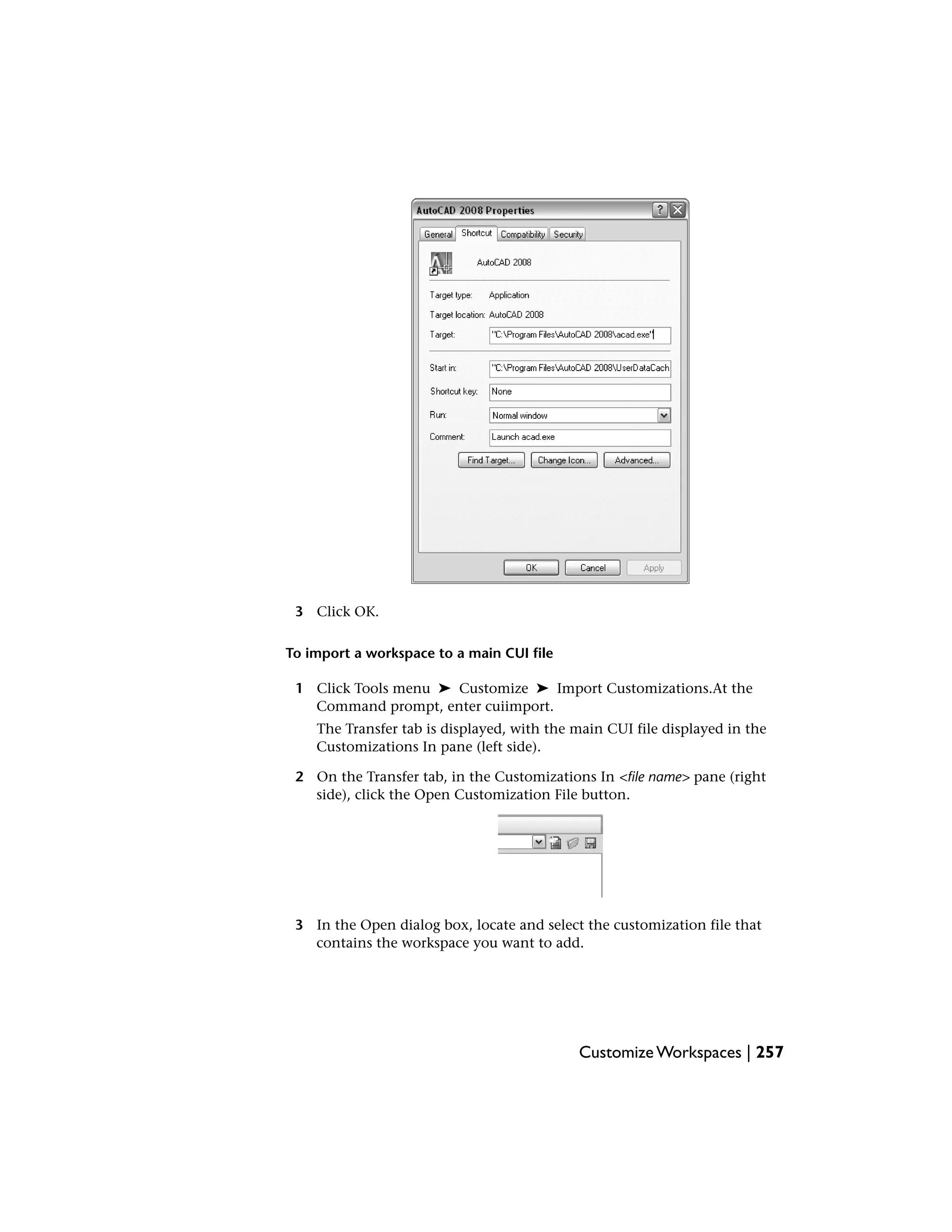
1 Right-click the program icon on the Windows desktop. Click Properties.
2 In the AutoCAD Properties dialog box, Shortcut tab, in the Target box,
edit the parameters for the switch using the following syntax:
“drive:pathnameacad.exe” [“drawing name”] [/switch “name”]
For Example, enter “d:AutoCAD 2008acad.exe” /w “MyWorkspace”
256 | Chapter 5 Customize the User Interface](https://image.slidesharecdn.com/acadacg-150207145020-conversion-gate02/75/Acad-acg-266-2048.jpg)


![USERS1-5
Utilities
No entries
Command Modifiers
No entries
Catalog of DIESEL Functions
Status retrieval, computation, and display are performed by DIESEL functions.
All functions have a limit of 10 parameters, including the function name itself.
If this limit is exceeded, you get a DIESEL error message.
+ (addition)
Returns the sum of the numbers val1, val2, …, val9.
$(+, val1 [, val2, …, val9])
If the current thickness is set to 5, the following DIESEL string returns 15.
$(+, $(getvar,thickness),10)
Quick Reference
Commands
No entries
SystemVariables
MENUECHO
Sets menu echo and prompt control bits
276 | Chapter 6 DIESEL](https://image.slidesharecdn.com/acadacg-150207145020-conversion-gate02/75/Acad-acg-286-2048.jpg)
![Utilities
No entries
Command Modifiers
No entries
- (subtraction)
Returns the result of subtracting the numbers val2 through val9 from val1.
$(-, val1 [, val2 , …, val9])
Quick Reference
Commands
No entries
SystemVariables
MENUECHO
Sets menu echo and prompt control bits
Utilities
No entries
Command Modifiers
No entries
* (multiplication)
Returns the result of multiplying the numbers val1, val2, …, val9.
$(*, val1 [, val2, …, val9])
- (subtraction) | 277](https://image.slidesharecdn.com/acadacg-150207145020-conversion-gate02/75/Acad-acg-287-2048.jpg)
![Quick Reference
Commands
No entries
SystemVariables
MENUECHO
Sets menu echo and prompt control bits
Utilities
No entries
Command Modifiers
No entries
/ (division)
Returns the result of dividing the number val1 by val2, …, val9.
$(/, val1 [, val2, …, val9])
Quick Reference
Commands
No entries
SystemVariables
MENUECHO
Sets menu echo and prompt control bits
278 | Chapter 6 DIESEL](https://image.slidesharecdn.com/acadacg-150207145020-conversion-gate02/75/Acad-acg-288-2048.jpg)

![Quick Reference
Commands
No entries
SystemVariables
MENUECHO
Sets menu echo and prompt control bits
Utilities
No entries
Command Modifiers
No entries
and
Returns the bitwise logical AND of the integers val1 through val9.
$(and, val1 [, val2,…, val9])
Quick Reference
Commands
No entries
SystemVariables
MENUECHO
Sets menu echo and prompt control bits
and | 283](https://image.slidesharecdn.com/acadacg-150207145020-conversion-gate02/75/Acad-acg-293-2048.jpg)
![Utilities
No entries
Command Modifiers
No entries
angtos
Returns the angular value in the format and precision specified.
$(angtos, value [, mode, precision])
Edits the given value as an angle in the format specified by the mode and
precision as defined for the analogous AutoLISPfunction. (The values for
mode are shown in the following table.) If mode and precision are omitted, it
uses the current values chosen by the UNITS command.
Angular units values
String formatMode value
Degrees0
De-
grees/minutes/seconds
1
Grads2
Radians3
Surveyor's units4
284 | Chapter 6 DIESEL](https://image.slidesharecdn.com/acadacg-150207145020-conversion-gate02/75/Acad-acg-294-2048.jpg)


![Utilities
No entries
Command Modifiers
No entries
if
Conditionally evaluates expressions.
$(if, expr, dotrue [, dofalse])
If expr is nonzero, it evaluates and returns dotrue. Otherwise, it evaluates
and returns dofalse. Note that the branch not chosen by expr is not evaluated.
Quick Reference
Commands
No entries
SystemVariables
MENUECHO
Sets menu echo and prompt control bits
Utilities
No entries
Command Modifiers
No entries
index
Returns the specified member of a comma-delimited string.
$(index, which, string)
if | 291](https://image.slidesharecdn.com/acadacg-150207145020-conversion-gate02/75/Acad-acg-301-2048.jpg)
![Assumes that the string argument contains one or more values delimited by
the macro argument separator character, the comma. The which argument
selects one of these values to be extracted, with the first item numbered 0.
This function is most frequently used to extract X, Y, or Z coordinate values
from point coordinates returned by $(getvar).
Applications can use this function to retrieve values stored as comma-delimited
strings from the USERS1-5 system variables.
Quick Reference
Commands
No entries
SystemVariables
MENUECHO
Sets menu echo and prompt control bits
Utilities
No entries
Command Modifiers
No entries
nth
Evaluates and returns the argument selected by which.
$(nth, which, arg0 [, arg1,…, arg7])
If which is 0, nth returns arg0, and so on. Note the difference between $(nth)
and $(index); $(nth)returns one of a series of arguments to the function,
while $(index) extracts a value from a comma-delimited string passed as a
single argument. Arguments not selected by which are not evaluated.
292 | Chapter 6 DIESEL](https://image.slidesharecdn.com/acadacg-150207145020-conversion-gate02/75/Acad-acg-302-2048.jpg)
![Quick Reference
Commands
No entries
SystemVariables
MENUECHO
Sets menu echo and prompt control bits
Utilities
No entries
Command Modifiers
No entries
or
Returns the bitwise logical OR of the integers val1 through val9.
$(or, val1 [, val2,…, val9])
Quick Reference
Commands
No entries
SystemVariables
MENUECHO
Sets menu echo and prompt control bits
or | 293](https://image.slidesharecdn.com/acadacg-150207145020-conversion-gate02/75/Acad-acg-303-2048.jpg)
![Utilities
No entries
Command Modifiers
No entries
rtos
Returns the real value in the format and precision specified.
$(rtos, value [, mode, precision])
Edits the given value as a real number in the format specified by the mode and
precision as defined by the analogous AutoLISP function. If mode and
precision are omitted, it uses the current values selected with the UNITS
command.
Edits the given value as a real number in the format specified by mode and
precision. If mode and precision are omitted, it uses the current values
selected with the UNITS command.
Quick Reference
Commands
No entries
SystemVariables
MENUECHO
Sets menu echo and prompt control bits
294 | Chapter 6 DIESEL](https://image.slidesharecdn.com/acadacg-150207145020-conversion-gate02/75/Acad-acg-304-2048.jpg)
![Utilities
No entries
Command Modifiers
No entries
strlen
Returns the length of string in characters.
$(strlen, string)
Quick Reference
Commands
No entries
SystemVariables
MENUECHO
Sets menu echo and prompt control bits
Utilities
No entries
Command Modifiers
No entries
substr
Returns the substring of string, starting at character start and extending for
length characters.
$(substr, string, start [, length])
strlen | 295](https://image.slidesharecdn.com/acadacg-150207145020-conversion-gate02/75/Acad-acg-305-2048.jpg)

![Utilities
No entries
Command Modifiers
No entries
xor
Returns the bitwise logical XOR of the integers val1 through val9.
$(xor, val1 [, val2,…, val9])
Quick Reference
Commands
No entries
SystemVariables
MENUECHO
Sets menu echo and prompt control bits
xor | 297](https://image.slidesharecdn.com/acadacg-150207145020-conversion-gate02/75/Acad-acg-307-2048.jpg)


![Before you can use an AutoLISP application, it must first be loaded. You can
use the APPLOAD command or the AutoLISP load function to load an
application. Loading an AutoLISP application loads the AutoLISP code from
the LSP file into your system's memory.
Loading an application with the load function involves entering AutoLISP
code at the Command prompt. If the load function is successful, it displays
the value of the last expression in the file at the command prompt. This is
usually the name of the last function defined in the file or instructions on
using the newly loaded function. If load fails, it returns an AutoLISP error
message. A load failure can be caused by incorrect coding in the file or by
entering the wrong file name at the command prompt. The syntax for the
load function is
(load filename [onfailure])
This syntax shows that the load function has two arguments: filename, which
is required, and onfailure, which is optional. When loading an AutoLISP file
at the command prompt, you typically supply only the filename argument.
The following example loads the AutoLISP file newfile.lsp.
Command: (load "newfile")
The .lsp extension is not required. This format works for any LSP file in the
current library path.
To load an AutoLISP file that is not in the library path, you must provide the
full path and file name as the filename argument.
Command: (load "d:/files/morelisp/newfile")
NOTE When specifying a directory path, you must use a slash (/) or two backslashes
() as the separator, because a single backslash has a special meaning in AutoLISP.
See also:
■ Overview of File Organization (page 7)
Quick Reference
Commands
APPLOAD
Loads and unloads applications and defines which applications to load at
startup
Use AutoLISP Applications | 331](https://image.slidesharecdn.com/acadacg-150207145020-conversion-gate02/75/Acad-acg-341-2048.jpg)


![ObjectARX program successfully, it returns the program name. The syntax for
the arxload function is as follows:
(arxload filename [onfailure])
The two arguments for the arxload function are filename and onfailure. As
with the load function, the filename argument is required and must be the
complete path name description of the ObjectARX program file to load. The
onfailure argument is optional and typically not used when you load
ObjectARX programs from the command prompt. The following example
loads the ObjectARX application myapp.arx.
(arxload "myapp")
As with AutoLISP files, AutoCAD searches the library path for the specified
file. If you need to load a file that is not in the library path, you must provide
the full path name description of the file.
NOTE When specifying a directory path, you must use a slash (/) or two backslashes
() as the separator, because a single backslash has a special meaning in AutoLISP.
Attempting to load an application that has previously been loaded results in
an error. Before using arxload you should use the arx function to check the
currently loaded applications.
To unload an application with AutoLISP, use the arxunload function. The
following example unloads the myapp application.
(arxunload "myapp")
Using the arxunload function not only removes the application from memory
but also removes the command definitions associated with that application.
See also:
■ Overview of File Organization (page 7)
Quick Reference
Commands
ARX
Loads, unloads, and provides information about ObjectARX applications
Use ObjectARX Applications | 343](https://image.slidesharecdn.com/acadacg-150207145020-conversion-gate02/75/Acad-acg-353-2048.jpg)


![the closest orthogonal vector. This is similar to the action of the snap grid in
AutoCAD.
The following example constructs a shape named DBOX with an arbitrarily
assigned shape number of 230.
*230,6,DBOX
014,010,01C,018,012,0
The preceding sequence of specification bytes defines a box one unit high
byone unit wide, with a diagonal line running from the lower left to the upper
right. After saving the file as dbox.shp, use the COMPILE command to generate
the dbox.shx file. Use the LOAD command to load the shape file containing
this definition, and then use the SHAPE command as follows:
Command: shape
Enter shape name or [?]: dbox
Specify insertion point: 1,1
Specify height <current>: 2
Specify rotation angle <current>: 0
The resulting shape is shown in the following illustration.
Quick Reference
Commands
LOAD
Makes shapes available for use by the SHAPE command
SHAPE
Inserts a shape from a shape file that has been loaded using LOAD
Vector Length and Direction Code | 355](https://image.slidesharecdn.com/acadacg-150207145020-conversion-gate02/75/Acad-acg-365-2048.jpg)


![*00429,24,ucr!
2,14,8,(-2,-6),1,064,06C,030,044,04C,030,064,06C,010,01C,014,2,
020,14,8,(-7,-3),0
*0042A,23,ucr'
2,14,8,(-2,-6),054,1,014,010,06C,030,012,014,016,038,2,060,03C,
14,8,(-5,-3),0
*0042B,24,ucrs
2,14,8,(-2,-6),1,030,012,014,016,038,03C,064,2,050,1,06C,2,020,
14,8,(-5,-3),0
*0042C,21,ucr]
2,14,8,(-2,-6),1,030,012,014,016,038,03C,064,2,060,06C,
14,8,(-4,-3),0
*0042D,25,ucr'
2,14,8,(-2,-6),014,1,01E,020,012,024,028,020,024,016,028,01A,2,
060,05C,14,8,(-4,-3),00,
*0042E,26,ucr!
2,14,8,(-2,-6),1,064,03C,010,024,012,010,01E,04C,01A,018,016,024,
2,050,03C,14,8,(-4,-3),0
*0042F,22,ucrya
2,14,8,(-2,-6),1,022,020,044,038,01A,02C,01E,030,02C,2,020,
14,8,(-4,-3),0
*00430,25,lcra
2,14,8,(-2,-6),014,1,024,012,020,01E,014,04C,014,01A,028,016,2,
060,01C,14,8,(-4,-3),0
*00431,22,lcrb
2,14,8,(-2,-6),044,030,1,038,04C,030,012,016,038,2,02C,060,
14,8,(-4,-3),0
*00432,24,lcrv
2,14,8,(-2,-6),1,044,020,10,(1,-36),028,030,10,(1,-36),038,2,060,
14,8,(-4,-3),0
*00433,16,lcrg
2,14,8,(-2,-6),1,044,030,2,04C,020,14,8,(-3,-3),0
*00434,24,lcrd
2,14,8,(-2,-6),01C,1,014,010,034,012,010,04C,028,030,01C,2,014,
020,14,8,(-4,-3),00,
*00435,20,lcre
2,14,04B,024,1,030,012,016,028,01A,02C,01E,020,2,030,
14,8,(-4,-3),0
*00436,23,lcrg
2,14,8,(-2,-6),1,042,2,048,1,04E,2,028,1,044,2,040,04C,
14,8,(-4,-3),0
*00437,25,lcrz
2,14,8,(-2,-6),034,1,012,020,01E,01A,018,010,01E,01A,028,016,2,
416 | Chapter 9 Shapes and Shape Fonts](https://image.slidesharecdn.com/acadacg-150207145020-conversion-gate02/75/Acad-acg-426-2048.jpg)


![SystemVariables
No entries
Utilities
No entries
Command Modifiers
No entries
Use Big FontText in a Drawing
To use a Big Font for drawing text, you set up a text style and then specify the
name of the Big Font file.
To use a Big Font for drawing text, you must set up a text style by using the
STYLE command and then specify the name of the Big Font file. The same
text style can use a normal ASCII font as well; enter only the two file names,
separated by a comma. The following example uses the command line version
of the STYLE command. To enable Big Fonts from the Text Style dialog box,
choose the Use Big Font option.
Command: -style
Enter name of text style or [?] <current>: style_name
Specify full font name or font file name (TTF or SHX): txt,greek
AutoCAD assumes that the first name is the normal font and that the second
is the big font.
If you enter only one name, AutoCAD assumes it is the normal font and
removes any associated Big Font.
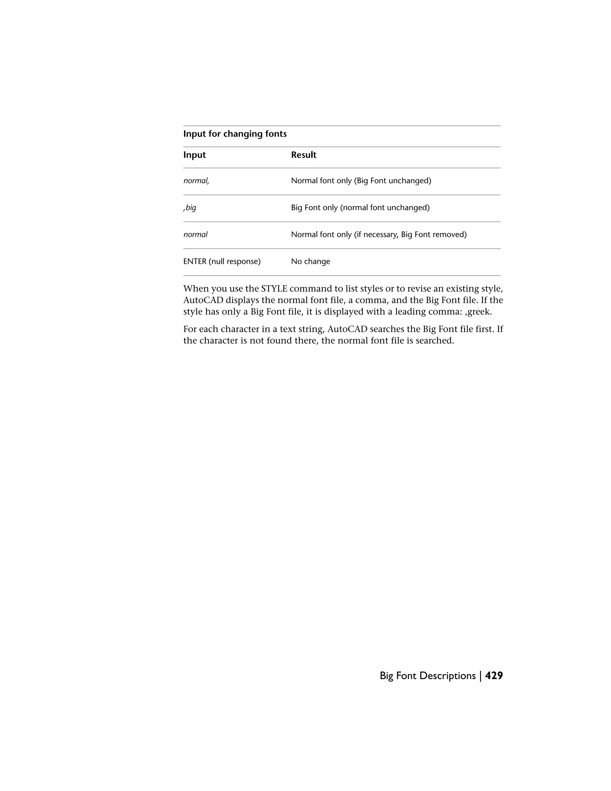
By using leading or trailing commas when specifying the font file names, you
can change one font without affecting the other, as shown in the following
table.
Input for changing fonts
ResultInput
Both normal and Big Font specifiednormal, big
428 | Chapter 9 Shapes and Shape Fonts](https://image.slidesharecdn.com/acadacg-150207145020-conversion-gate02/75/Acad-acg-438-2048.jpg)

![SystemVariables
No entries
Utilities
No entries
Command Modifiers
No entries
Superscripts and Subscripts in SHX Files
You can modify shape definition files to improve their ability to display
superscripts and subscripts.
The AutoCAD SHX fonts have limited superscript and subscript capabilities.
However, it is relatively easy to modify shape definition files to improve
superscript and subscript capability.
Creating superscripts and subscripts requires two steps. First, the “imaginary
pen” that is creating the text, vector by vector, on your screen needs to be
shifted up or down. Then, the font “scale” needs to be reduced. In addition,
the reverse process has to take place to return to the normal font. The font
needs to recognize four new keys: two for superscripts and two for subscripts.
To avoid altering the existing font definitions, you can access these with the
numeric keypad on your keyboard.
To add superscript and subscript definitions to a font
This example procedure is based on the AutoCAD Romans font file, although
a similar method applies to any AutoCAD font. This procedure adds four new
shape definitions to a font: super_on, super_off, sub_on, and sub_off, which
control the position and size of the characters that follow. For simplicity, this
example replaces the left- and right-bracket characters ([and]) and the left and
right curly brace characters ({and}) with the new characters. You may choose
to replace other characters or use a shape number in the extended range (ASCII
codes 128 through 256). If you use an extended shape number, you need to
use the %%nnn method (where nnn is the ASCII value of the character) for
placing the new characters.
1 Edit your SHP file with an ASCII text editor.
434 | Chapter 9 Shapes and Shape Fonts](https://image.slidesharecdn.com/acadacg-150207145020-conversion-gate02/75/Acad-acg-444-2048.jpg)
![2 Search for the shape definitions of the characters you are replacing. To
comment out those definitions so the new definitions can take their
place, insert a semicolon in front of each line of the shape definition.
The shape definition may continue for a number of lines.
The left- and right-bracket characters have ASCII values of 91 and 93 (05B
and 05D hex values, if the font is Unicode). The left and right curly brace
characters have ASCII values of 123 and 125 (07B and 07D hex).
3 Add the first and second values on the second line of the definition, and
divide the total by 2 as shown in the following example:
*UNIFONT,6,Extended Simplex Roman for UNICODE
21,7,2,0 21 + 7 = 28, then 28 / 2 = 14. This number is used
later.
4 Add the following lines to the end of the SHP file:
*91,8,super_on
2,8,(0,14),003,2,1,0
*93,8,super_off
2,004,2,8,(0,-14),1,0
*123,8,sub_on
2,8,(0,-14),003,2,1,0
*125,8,sub_off
2,004,2,8,(0,14),1,0
Notice the 14 and -14 values in the preceding lines. They are Y axis offsets
for the imaginary pen. The value 14 is half the maximum height of a
character in this font, which is the correct approximation for superscripts
and subscripts. This value needs to be calculated for each font file, but
you can modify it any way you want.
5 Save the file.
6 Use the COMPILE command to compile the SHP file.
Once the shape is compiled and an appropriate style is defined, you can
access the new pen-up and pen-down commands by entering the [, ], {,
and } characters. The [ character initiates superscript and the ] character
returns from superscript to normal. The { character initiates subscript and
the } character returns from subscript to normal.
Superscripts and Subscripts in SHX Files | 435](https://image.slidesharecdn.com/acadacg-150207145020-conversion-gate02/75/Acad-acg-445-2048.jpg)


This document provides an overview and instructions for customizing AutoCAD 2008. It covers topics such as organizing customization files, creating custom commands, linetypes, and hatch patterns, customizing the user interface through menus and toolbars, using macros and AutoLISP, and more. The document is intended as a guide for customizing AutoCAD to meet company or individual needs and standards.


![Cimco edit 5 user guide[1]](https://cdn.slidesharecdn.com/ss_thumbnails/cimcoedit5userguide1-110305112440-phpapp01-thumbnail.jpg?width=640&height=640&fit=bounds)


