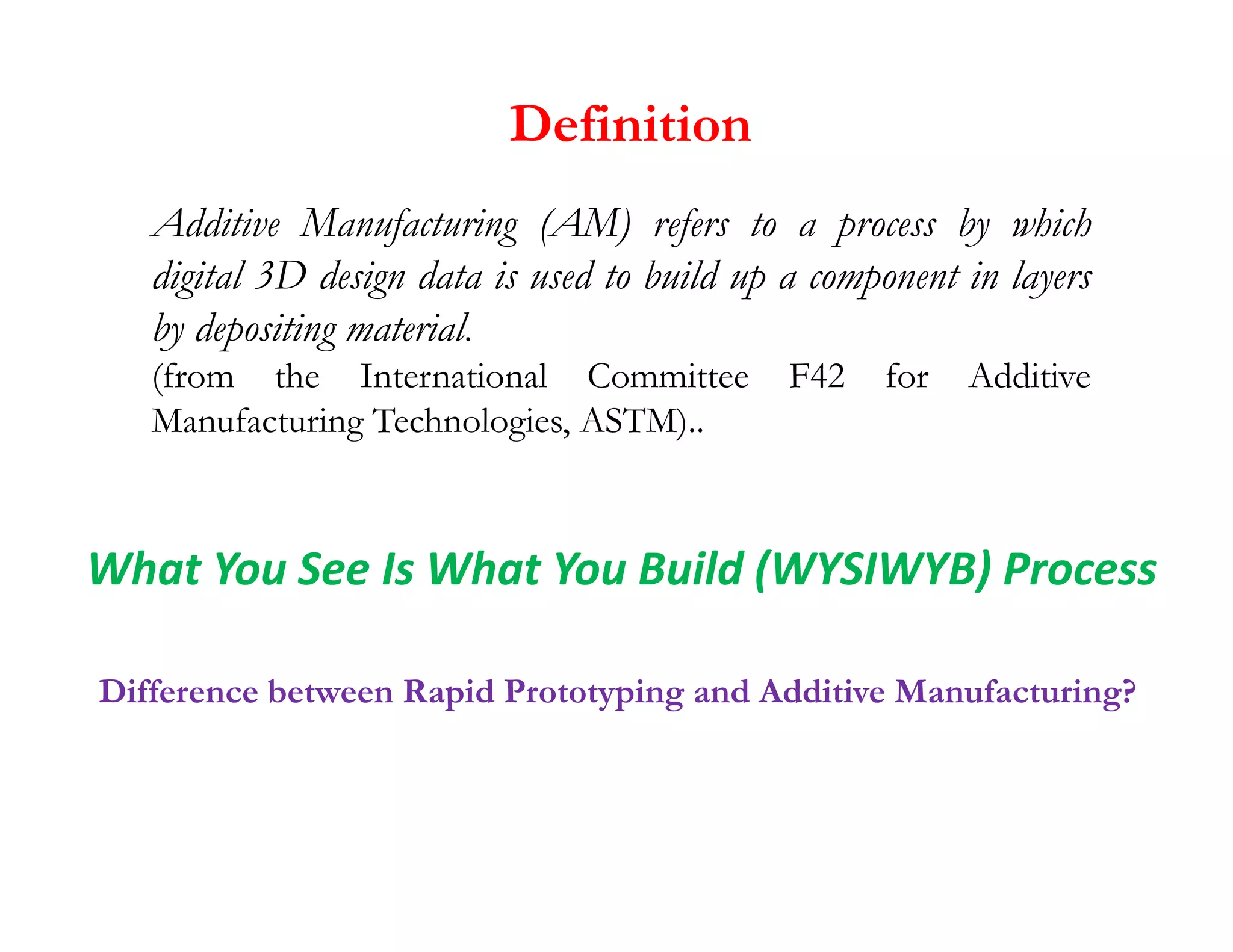
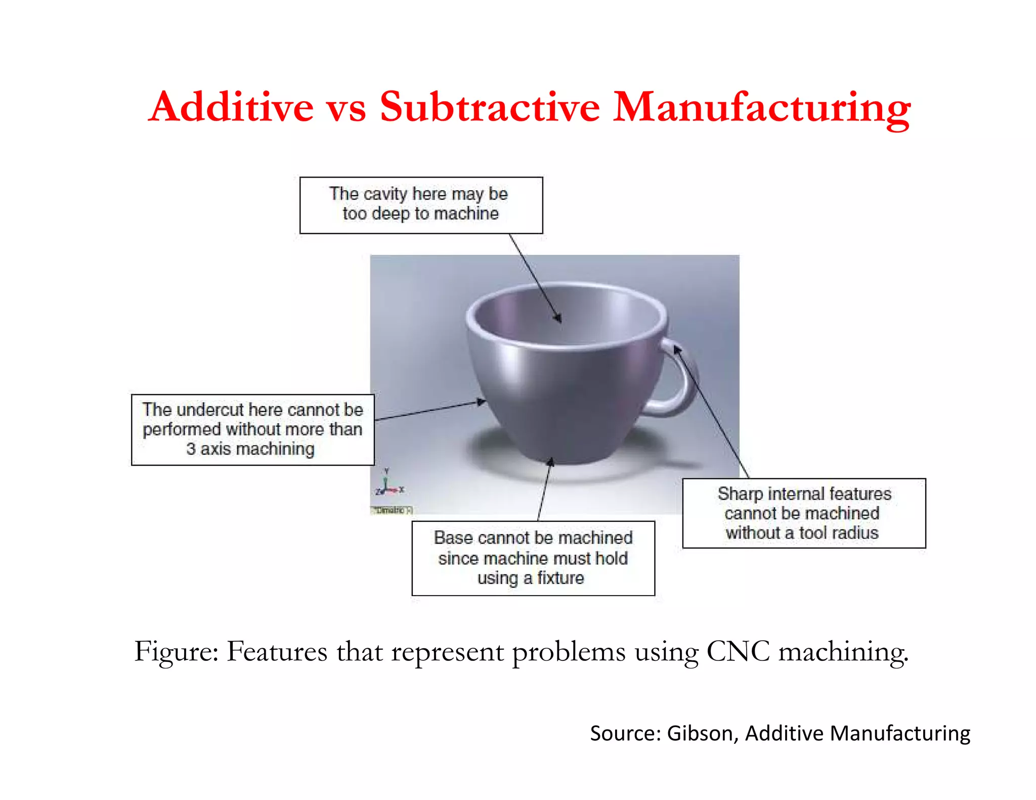
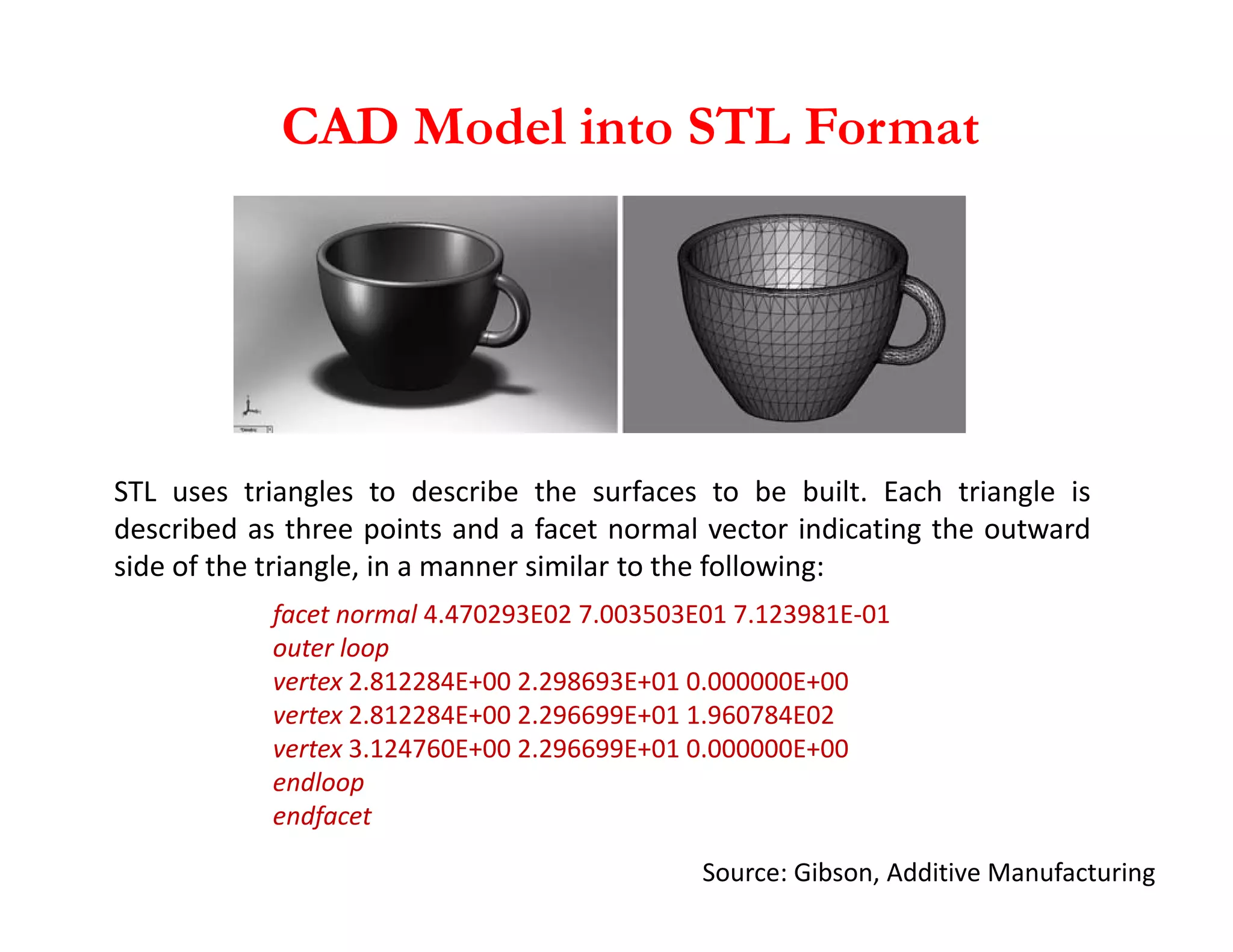
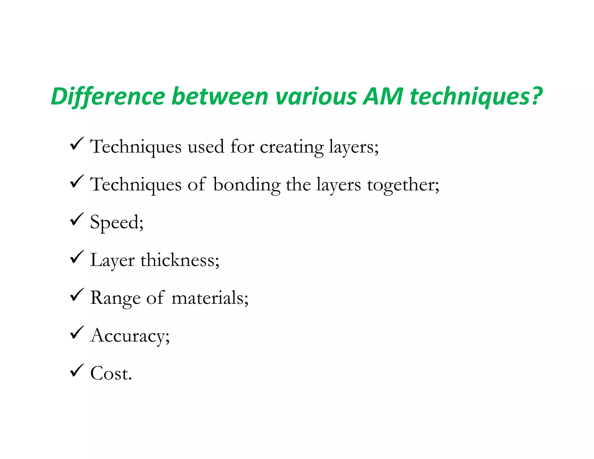
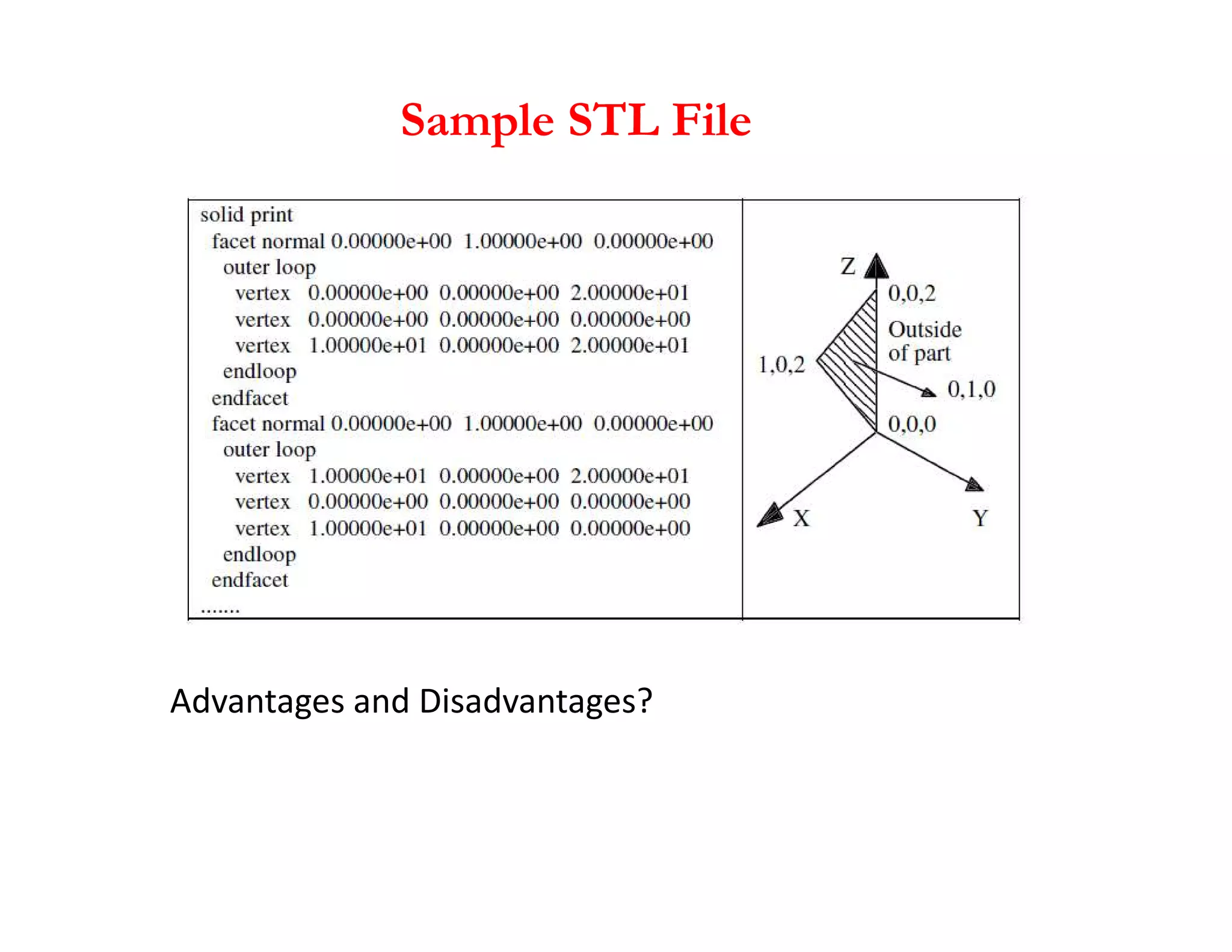
Additive Manufacturing
N. Sinha
Department of Mechanical Engineering
IIT Kanpur
Definition
Additive Manufacturing (AM) refers to a process by which
digital 3D design data is used to build up a component in layers
by depositing material.
(from the International Committee F42 for Additive
Manufacturing Technologies, ASTM)..
Difference between Rapid Prototyping and Additive Manufacturing?
What You See Is What You Build (WYSIWYB) Process
Additive vs Subtractive Manufacturing
 Part Complexity;
 Material;
 Speed;
 Part Quantity;
 Cost.
Additive vs Subtractive Manufacturing
Figure: Features that represent problems using CNC machining.
Source: Gibson, Additive Manufacturing
Generic AM Process
Source: Gibson, Additive Manufacturing
CAD Model into STL Format
STL uses triangles to describe the surfaces to be built. Each triangle is
Source: Gibson, Additive Manufacturing
facet normal 4.470293E02 7.003503E01 7.123981E-01
outer loop
vertex 2.812284E+00 2.298693E+01 0.000000E+00
vertex 2.812284E+00 2.296699E+01 1.960784E02
vertex 3.124760E+00 2.296699E+01 0.000000E+00
endloop
endfacet
STL uses triangles to describe the surfaces to be built. Each triangle is
described as three points and a facet normal vector indicating the outward
side of the triangle, in a manner similar to the following:
Generic AM Process
Source: Gibson, Additive Manufacturing
Effects of building using different layer thicknesses
Other Related Technologies
1. Reverse engineering technology
2. Computer aided engineering (CAE):
3D CAD model + Engineering analysis software packages
3. Haptic-based CAD
Source: Gibson, Additive Manufacturing
Difference between various AM techniques?
 Techniques used for creating layers;
 Techniques of bonding the layers together;
 Speed;
 Speed;
 Layer thickness;
 Range of materials;
 Accuracy;
 Cost.
Evolution
Source: Royal Academy of Engineering
Evolution
Source: Royal Academy of Engineering
Source
Google images
Current and Potential industries for Additive Manufacturing
Pros and Cons
Benefits
Source: SAVING project/Crucible Industrial Design Ltd.; Roland Berger
Benefits
Source: Roland Berger
Benefits
Source: Roland Berger
Future: Home Manufacturing
Old toothbrush
New toothbrush
Customization:
•Bristle hardness
•Colour
•Handle Style and shape
•Etc.
Home 3D Printer
Laser scanner to input
personalized data
Case Studies
Source: Royal Academy of Engineering
Introduction to Reverse Engineering
The primary input for AM is CAD file/model.
Suppose that for a part (to be copied, modified or
repaired)
 CAD was not used in the original design;
 there is inadequate documentation on the original
there is inadequate documentation on the original
design;
 the original CAD model is not sufficient to support
modification or manufacturing using modern methods;
 the original supplier is unable or unwilling to provide
additional parts.
Introduction to Reverse Engineering
“Examining competitive or similar or prior products in great
detail by dissecting them or literally taking them apart.”
- Dym  Little
Technological principles of a device through analysis of its
structure, function and operation.
“What does this do?”
“How does it do that?”
“Why would you want to do that?”
Introduction to Reverse Engineering
Purposes solved
 Dissection and analysis
 Experience and knowledge for an individual’s personal
database
 Competitive benchmarking
Introduction to Reverse Engineering
Reverse Engineering Process
1. Digitizing the parts
This step uses a reverse engineering device to collect raw
geometry of the object.
The data is usually in the form of coordinate points of
the object relative to a local coordinate system.
2. Building CAD models
This step converts the raw point data obtained from step
1 into a usable format.
Physical part
Physical part Physical part
CAD model Physical part
Prototype part
Example
General Integration of an AM Machine
1. Polymers
2. Metals
3. Ceramics
4. Composites
Polymers
a) ABS polymer
Material Classification
a) ABS polymer
b) Acrylics
c) Cellulose
d) Nylon
e) Polycarbonate
f) Thermoplastic polyester
g) Polyethylene
h) Polypropylene
i) Polyvinylchloride
Thermal Expansion Characteristics
Load-Displacement Characteristics
Metals Polymers
Metals: Characterized by a linear elastic region followed by a non-linear plastic
region.
Polymers:
 Generally brittle at temperatures much lower than Tg, but their ductility increases
as temperature rises.
 As the temperature increases to levels above Tg, a peak load is reached and a neck
begins to form.
 As the specimen approaches its fracture point, the load rises due to the stretching
of molecules.
Material Classification
Metals
a) Pure metals: Ti, Ta, Cu, Au, Ag
b) Alloys: Ti-based, Ni-based, Fe-based, Al-based, Co-based, Cu-based
Material/process considerations and control
methods
Absorptance
Processes of AM generally involve a direct interaction of powders with
laser beam. The determination of absorptance of powders is
particularly important to thermal development, because it allows one to
determine a suitable processing window free of a non-response of
powder due to an insufficient laser energy input or a pronounced
material evaporation due to an excessive energy input.
The absorptance is defined as the ratio of the absorbed radiation to the
incident radiation. The absorptance of powders has a direct influence
on the optical penetration depth δ of the radiation, which is defined as
the depth at which the intensity of the radiation inside the material falls
to 1/e (~37%) of the original value. Owing to the multiple reflection
effect, the δ measured in powders is larger than in bulk materials.
Surface tension and wettability
The liquid–solid wetting characteristics are crucial for a successful AM
process. The wetting behaviour of a partially melted LS system involves the
wetting between structural metal and liquid binder as well as the wetting
between the molten system and the solidified preprocessed layer. For the
completely melted LM/LMD systems, the second kind of wetting
behaviour prevails.
The wetting of a solid by a liquid is related to the surface tension of solid–
liquid ߛsl, solid–vapour ߛsv and liquid–vapour ߛlv interfaces. Wettability can
ߠ
liquid ߛsl, solid–vapour ߛsv and liquid–vapour ߛlv interfaces. Wettability can
be defined by the contact angle ߠ
The liquid wets the solid as cosߠ -1. A spreading coefficient has been
defined in literature
to describe the wetting behaviour and, normally, a large positive S favours
spreading of the liquid.
Viscosity
Besides the favourable wettability, it is required that the viscosity of the melt is
low enough such that it successfully spreads on the previously processed layer
and, in the case of LS, surrounds the solid structural particles. For a LS system
consisting of a solid–liquid mixture, the viscosity of the molten material µ is
expressed as
where µ is the base viscosity that includes temperature terms, Φ is the volume
where µ0 is the base viscosity that includes temperature terms, Φl is the volume
fraction of liquid phase and Φm is a critical volume fraction of solids above
which the mixture has essentially infinite viscosity. As to an LM or LMD
system with a complete liquid formation, the dynamic viscosity of the liquid is
defined by
where m is the atomic mass, k the Boltzmann constant, T the temperature and
ߛ the surface tension of the liquid.
Ceramics
AM technology has been successfully demonstrated its advantages in
producing ceramic parts through both “direct” and “indirect”
methods.
Indirect Methods
 These processes typically create a ceramic green body with a
high content of organic or inorganic binders.
 Then, binder burnout and densification of the green body are
conducted in a conventional sintering step.
Example: A ZrB2 part (fuel injector strut for aircraft engine),
alumina and silica cores and shells for investment casting, graphite
bipolar plates for fuel cells, and bio-ceramic bone scaffolds were
fabricated using SLS by laser scanning the mixture of ceramic
powder and binder and then removing the binder and sintering the
parts in a furnace.
Ceramics
Direct Methods
Direct fabrication of ceramic parts using AM processes is much
more challenging due to the high melting temperatures of
ceramics such as Al2O3 (  2000°C) and SiO2 (  1700°C), and
also the large thermal gradients, thermal stresses and residual
stresses associated with melting/resolidifying in the laser based
AM processes.
AM processes.
Example: SLM process was investigated to fabricate ceramic parts
from a mixture of zirconia and alumina by completely melting the
ceramic powder. The ceramic powder bed was preheated to a
temperature higher than 1600°C to reduce thermal stresses, and
nearly fully dense, crack-free parts were obtained without any post-
processing. Fully dense, net-shaped, alumina parts were produced
using LENS by direct laser melting of the ceramic powder.
Composites
 Composites are engineered or naturally occurring materials made from two or
more constituent materials with significantly different physical or chemical
properties that remain separate and distinct at the macroscopic or microscopic
scale within the finished structure but exhibit properties that cannot be achieved
by any of the materials acting alone.
 The materials in a composite can be mixed uniformly, resulting in a
homogeneous compound (uniform composite), or non-uniformly, resulting in
an inhomogeneous compound (e.g., functionally graded materials) in which the
composition varies gradually over volume, leading to corresponding changes in
the properties of the composite material.
Composites
Uniform Composites
 Uniform composites fabricated using AM processes are usually done by
employing a pre-prepared mixture of proper materials, such as a mixed powder
bed for SLS, SLM and 3DP, a filament in mixed materials for FDM, a composite
laminate for LOM, or a mixture of liquid photocurable resin with particulates for
SLA.
 The composite materials that can be produced with AM technology include a
polymer matrix, ceramic matrix, metal matrix, and fiber and particulate reinforced
composites.
 Metal-metal composites (e.g., Fe-Cu and stainless steelCu), metal-ceramic
composites (e.g., WC-Cu, WC-Co, WC-CuFeCo, TiC-Ni/Co/Mo, ZeB2-Cu, and
TiB2-Ni), and ceramic-ceramic composites (e.g., Si-SiC) have been processed by
SLS/SLM.
 These processed composites can be classified into two categories: those that
aim to facilitate the process using a liquid-phase sintering mechanism, and those
that combine various materials to achieve properties not possible with a single
material.
Composites
Uniform Composites
 Examples of composites in the first category include Fe-Cu and stainless steel-
Cu used in SLS, in which Cu acts as a binder to bond Fe or stainless steel particles
rather than a reinforcement phase to enhance the mechanical or other properties
of the final product.
 An example of the second category is the bio-composite poly-epsilon-
caprolactone and hydroxyapatite (PCL/HA) bone scaffold fabricated using SLS,
with the addition of HA to enhance the strength and biocompatibility of PCL.
 By developing a feedstock filament with the proper composite, polymer-metal
and polymer-ceramic composites could be produced with FDM. ABS-Iron
composites have been made using FDM with a single-screw extruder by
appropriately producing an iron particulate-filled polymeric filament. Fibers, such
as short glass fibers and nanofibers (vapor-grown carbon fibers), have been added
into ABS filaments to improve the mechanical properties of the parts built using
FDM.
Composites: Functionally Graded Materials
Stepwise Graded Structures
An example is a spark plug which gradient is formed by changing its
composition from a refractory ceramic to a metal
Continuous Graded Structures
 An example is the human bone which gradient is formed by its
change in porosity and composition;
 Change in porosity happens across the bone because of miniature
blood vessels inside the bone.
Functionally Graded Materials (FGMs)
FGMs can be obtained by
layered mixing of two
materials of different thermo-
mechanical properties with
different volume ratio by
gradual changing from layer
to layer.
Composites: Functionally Graded Materials
The human bone is a an example of a FGM. It is a mix
of collagen (ductile protein polymer) and hydroxyapatite
(brittle calcium phospate ceramic).
A gradual increase in the pore distribution from the
interior to the surface can pass on properties such as
shock resistance, thermal insulation, catalytic efficiency,
and the relaxation of the thermal stress. The
distribution of the porosity affects the tensile strength
and the Young’s modulus.
Composites: Functionally Graded Materials
Current applications of FGMs include:
 Structural walls that combine two or
more functions including thermal and
sound insulation;
 Enhanced sports equipment such as golf
clubs, tennis rackets, and skis with added
graded combinations of flexibility,
elasticity, or rigidity;
 Enhanced body coatings for cars
including graded coatings with particles
such as dioxide/mica.
AM Unique Capabilities
Various types of nano/microstructures
can be achieved by careful control of the
process parameters (e.g. laser power, scan
rate) for a particular material, and can
vary from point to point within a
structure.
The ability to simultaneously control a part's nano/microstructure,
mesostructure, and macrostructure simply by changing process
parameters and CAD data is a capablity of AM which is unparalleled
using conventional manufacturing.
AM Unique Capabilities
 When building parts in an additive manner, one always has access to
the inside of the part.
 Component can be inserted and it is possible to fabricate operational
 Component can be inserted and it is possible to fabricate operational
mechanisms in some AM processes.
Pulley-driven snake-like robot
Source: Gibson.
AM Unique Capabilities
The concept of functionally graded materials, or heterogeneous materials, has
received considerable attention.
However, manufacturing useful parts from these materials often has been
problematic.
Example: Turbine blade for a jet engine
I. The outside of the blade must be resistant to high temperature and very
stiff to prevent elongation;
II. The blade root must be ductile and has high fatigue life;
A significant issue hindering the adoption of AM’s material complexity
is the lack of design and CAD tools that enable representation and
reasoning with multiple materials.
II. The blade root must be ductile and has high fatigue life;
III. Blade interiors must have high heat conductivity so that the blades can be
cooled.
A part with complex shape that requires different material properties in
different regions.
No single material is ideal for this range of properties.
Process Planning in Layered Manufacturing
There are four main planning tasks:
(i) orientation optimization,
(ii) support design,
(iii) slicing, and
(iv) tool-path/scanning-path planning.
Process Planning in Layered Manufacturing
Sample STL File
Advantages and Disadvantages?
STL File
Advantages
(i) Provides a simple method of representing 3D CAD data
(ii) A de facto standard and has been used by most CAD systems and
RP systems
(iii) It can provide small and accurate files for data transfer for certain
shapes
Disadvantages
Disadvantages
(i) The STL file is many times larger than the original CAD data file
(ii) The geometry flaws exist in the STL file
(iii) The subsequent slicing of large STL files can take many hours
STL File Problems
Valid vs. Invalid Tessellated Models
STL File Repair
• One of the most important additive manufacturing technologies
currently available.
• The first ever commercial RP systems were resin-based systems
commonly called stereolithography or SLA.
• The resin is a liquid photosensitive polymer that cures or hardens
Stereolithography
when exposed to ultraviolet radiation.
• This technique involves the curing or solidification of a liquid
photosensitive polymer through the use of the irradiation light
source.
• The source supplies the energy that is needed to induce a
chemical reaction (curing reaction), bonding large no of small
molecules and forming a highly cross-linked polymer.
• The UV light comes from a laser,
which is controlled to scan across
the surface according to the
cross-section of the part that
corresponds to the layer.
• The laser penetrates into the
resin for a short distance that
corresponds to the layer
thickness.
thickness.
• The first layer is bonded to a
platform, which is placed just
below the surface of the resin
container.
• The platform lowers by one layer
thickness and the scanning is
performed for the next layer. This
process continues until the part
has been completed.
A part produced by stereolithography (Source: 3D Systems, Inc.).
Facts About STL
• Each layer is 0.076 mm to 0.50 mm (0.003
in to 0.020 in.) thick
– Thinner layers provide better resolution and more
intricate shapes; but processing time is longer
• Starting materials are liquid monomers
• Polymerization occurs on exposure to UV
light produced by laser scanning beam
– Scanning speeds ~ 500 to 2500 mm/s
Part Build Time in STL
Time to complete a single layer :
d
i
i T
vD
A
T +
=
where Ti = time to complete layer i; Ai = area of layer i; v =
average scanning speed of the laser beam at the surface;
D = diameter of the “spot size,” assumed circular; and Td =
delay time between layers to reposition the worktable
Part Build Time in STL - continued
Once the Ti values have been determined for all layers,
then the build cycle time is:
∑
=
=
l
n
i
i
c T
T
1
where Tc = STL build cycle time; and nl = number of layers
used to approximate the part
 Time to build a part ranges from one hour for small
parts of simple geometry up to several dozen hours for
complex parts
Numerical Problem
A prototype of a tube with a square cross-section is to be
fabricated using stereolithography. The outside dimension
of the square = 100 mm and the inside dimension = 90 mm
(wall thickness = 5 mm except at corners). The height of
the tube (z-direction) = 80 mm. Layer thickness = 0.10 mm.
The diameter of the laser beam (“spot size”) = 0.25 mm,
and the beam is moved across the surface of the
photopolymer at a velocity of 500 mm/s. Compute an
estimate for the time required to build the part, if 10 s are
lost each layer to lower the height of the platform that holds
the part. Neglect the time for postcuring.
Numerical Problem: Solution
Layer area Ai is same for all layers.
Ai = 1002-902 = 1900 mm2.
Time to complete one layer Ti is same for all layers.
Ti = (1900 mm2)/(0.25 mm)(500mm/s)+10 s = 25.2 s
Number of layers
Number of layers
nl = (80 mm)/(0.10 mm/layer) = 800 layers
Tc = 800(25.2) = 20,160 s = 336.0 min = 5.6 hr
How layer by layer adhesion takes place
in stereolithography?
The new layer adheres to the previous one because the
depth of penetration of each pulse of laser is greater than
the thickness of the layer and hence over cures the prior
layer.
This process is repeated as many times as is necessary to
recreate the entire object layer by layer. When completed,
the platen is raised from the vat and the model is ready for
removal of the support structure and postcuring.

Additive_Manufacturing I.pdf

  • 1.
    Additive Manufacturing N. Sinha Departmentof Mechanical Engineering IIT Kanpur
  • 6.
    Definition Additive Manufacturing (AM)refers to a process by which digital 3D design data is used to build up a component in layers by depositing material. (from the International Committee F42 for Additive Manufacturing Technologies, ASTM).. Difference between Rapid Prototyping and Additive Manufacturing? What You See Is What You Build (WYSIWYB) Process
  • 7.
    Additive vs SubtractiveManufacturing Part Complexity; Material; Speed; Part Quantity; Cost.
  • 8.
    Additive vs SubtractiveManufacturing Figure: Features that represent problems using CNC machining. Source: Gibson, Additive Manufacturing
  • 9.
    Generic AM Process Source:Gibson, Additive Manufacturing
  • 10.
    CAD Model intoSTL Format STL uses triangles to describe the surfaces to be built. Each triangle is Source: Gibson, Additive Manufacturing facet normal 4.470293E02 7.003503E01 7.123981E-01 outer loop vertex 2.812284E+00 2.298693E+01 0.000000E+00 vertex 2.812284E+00 2.296699E+01 1.960784E02 vertex 3.124760E+00 2.296699E+01 0.000000E+00 endloop endfacet STL uses triangles to describe the surfaces to be built. Each triangle is described as three points and a facet normal vector indicating the outward side of the triangle, in a manner similar to the following:
  • 11.
    Generic AM Process Source:Gibson, Additive Manufacturing Effects of building using different layer thicknesses
  • 12.
    Other Related Technologies 1.Reverse engineering technology 2. Computer aided engineering (CAE): 3D CAD model + Engineering analysis software packages 3. Haptic-based CAD Source: Gibson, Additive Manufacturing
  • 13.
    Difference between variousAM techniques? Techniques used for creating layers; Techniques of bonding the layers together; Speed; Speed; Layer thickness; Range of materials; Accuracy; Cost.
  • 14.
  • 15.
  • 16.
    Source Google images Current andPotential industries for Additive Manufacturing
  • 17.
  • 18.
    Benefits Source: SAVING project/CrucibleIndustrial Design Ltd.; Roland Berger
  • 19.
  • 20.
  • 21.
    Future: Home Manufacturing Oldtoothbrush New toothbrush Customization: •Bristle hardness •Colour •Handle Style and shape •Etc. Home 3D Printer Laser scanner to input personalized data
  • 22.
    Case Studies Source: RoyalAcademy of Engineering
  • 23.
    Introduction to ReverseEngineering The primary input for AM is CAD file/model. Suppose that for a part (to be copied, modified or repaired) CAD was not used in the original design; there is inadequate documentation on the original there is inadequate documentation on the original design; the original CAD model is not sufficient to support modification or manufacturing using modern methods; the original supplier is unable or unwilling to provide additional parts.
  • 24.
    Introduction to ReverseEngineering “Examining competitive or similar or prior products in great detail by dissecting them or literally taking them apart.” - Dym Little Technological principles of a device through analysis of its structure, function and operation. structure, function and operation. “What does this do?” “How does it do that?” “Why would you want to do that?”
  • 25.
    Introduction to ReverseEngineering Purposes solved Dissection and analysis Experience and knowledge for an individual’s personal database Competitive benchmarking
  • 26.
    Introduction to ReverseEngineering Reverse Engineering Process 1. Digitizing the parts This step uses a reverse engineering device to collect raw geometry of the object. The data is usually in the form of coordinate points of The data is usually in the form of coordinate points of the object relative to a local coordinate system. 2. Building CAD models This step converts the raw point data obtained from step 1 into a usable format. Physical part Physical part Physical part CAD model Physical part Prototype part
  • 27.
  • 28.
  • 29.
    1. Polymers 2. Metals 3.Ceramics 4. Composites Polymers a) ABS polymer Material Classification a) ABS polymer b) Acrylics c) Cellulose d) Nylon e) Polycarbonate f) Thermoplastic polyester g) Polyethylene h) Polypropylene i) Polyvinylchloride
  • 30.
  • 31.
    Load-Displacement Characteristics Metals Polymers Metals:Characterized by a linear elastic region followed by a non-linear plastic region. Polymers: Generally brittle at temperatures much lower than Tg, but their ductility increases as temperature rises. As the temperature increases to levels above Tg, a peak load is reached and a neck begins to form. As the specimen approaches its fracture point, the load rises due to the stretching of molecules.
  • 32.
    Material Classification Metals a) Puremetals: Ti, Ta, Cu, Au, Ag b) Alloys: Ti-based, Ni-based, Fe-based, Al-based, Co-based, Cu-based
  • 33.
    Material/process considerations andcontrol methods Absorptance Processes of AM generally involve a direct interaction of powders with laser beam. The determination of absorptance of powders is particularly important to thermal development, because it allows one to determine a suitable processing window free of a non-response of powder due to an insufficient laser energy input or a pronounced powder due to an insufficient laser energy input or a pronounced material evaporation due to an excessive energy input. The absorptance is defined as the ratio of the absorbed radiation to the incident radiation. The absorptance of powders has a direct influence on the optical penetration depth δ of the radiation, which is defined as the depth at which the intensity of the radiation inside the material falls to 1/e (~37%) of the original value. Owing to the multiple reflection effect, the δ measured in powders is larger than in bulk materials.
  • 34.
    Surface tension andwettability The liquid–solid wetting characteristics are crucial for a successful AM process. The wetting behaviour of a partially melted LS system involves the wetting between structural metal and liquid binder as well as the wetting between the molten system and the solidified preprocessed layer. For the completely melted LM/LMD systems, the second kind of wetting behaviour prevails. The wetting of a solid by a liquid is related to the surface tension of solid– liquid ߛsl, solid–vapour ߛsv and liquid–vapour ߛlv interfaces. Wettability can ߠ liquid ߛsl, solid–vapour ߛsv and liquid–vapour ߛlv interfaces. Wettability can be defined by the contact angle ߠ The liquid wets the solid as cosߠ -1. A spreading coefficient has been defined in literature to describe the wetting behaviour and, normally, a large positive S favours spreading of the liquid.
  • 35.
    Viscosity Besides the favourablewettability, it is required that the viscosity of the melt is low enough such that it successfully spreads on the previously processed layer and, in the case of LS, surrounds the solid structural particles. For a LS system consisting of a solid–liquid mixture, the viscosity of the molten material µ is expressed as where µ is the base viscosity that includes temperature terms, Φ is the volume where µ0 is the base viscosity that includes temperature terms, Φl is the volume fraction of liquid phase and Φm is a critical volume fraction of solids above which the mixture has essentially infinite viscosity. As to an LM or LMD system with a complete liquid formation, the dynamic viscosity of the liquid is defined by where m is the atomic mass, k the Boltzmann constant, T the temperature and ߛ the surface tension of the liquid.
  • 36.
    Ceramics AM technology hasbeen successfully demonstrated its advantages in producing ceramic parts through both “direct” and “indirect” methods. Indirect Methods These processes typically create a ceramic green body with a high content of organic or inorganic binders. Then, binder burnout and densification of the green body are conducted in a conventional sintering step. Example: A ZrB2 part (fuel injector strut for aircraft engine), alumina and silica cores and shells for investment casting, graphite bipolar plates for fuel cells, and bio-ceramic bone scaffolds were fabricated using SLS by laser scanning the mixture of ceramic powder and binder and then removing the binder and sintering the parts in a furnace.
  • 37.
    Ceramics Direct Methods Direct fabricationof ceramic parts using AM processes is much more challenging due to the high melting temperatures of ceramics such as Al2O3 ( 2000°C) and SiO2 ( 1700°C), and also the large thermal gradients, thermal stresses and residual stresses associated with melting/resolidifying in the laser based AM processes. AM processes. Example: SLM process was investigated to fabricate ceramic parts from a mixture of zirconia and alumina by completely melting the ceramic powder. The ceramic powder bed was preheated to a temperature higher than 1600°C to reduce thermal stresses, and nearly fully dense, crack-free parts were obtained without any post- processing. Fully dense, net-shaped, alumina parts were produced using LENS by direct laser melting of the ceramic powder.
  • 38.
    Composites Composites areengineered or naturally occurring materials made from two or more constituent materials with significantly different physical or chemical properties that remain separate and distinct at the macroscopic or microscopic scale within the finished structure but exhibit properties that cannot be achieved by any of the materials acting alone. The materials in a composite can be mixed uniformly, resulting in a homogeneous compound (uniform composite), or non-uniformly, resulting in an inhomogeneous compound (e.g., functionally graded materials) in which the an inhomogeneous compound (e.g., functionally graded materials) in which the composition varies gradually over volume, leading to corresponding changes in the properties of the composite material.
  • 39.
    Composites Uniform Composites Uniformcomposites fabricated using AM processes are usually done by employing a pre-prepared mixture of proper materials, such as a mixed powder bed for SLS, SLM and 3DP, a filament in mixed materials for FDM, a composite laminate for LOM, or a mixture of liquid photocurable resin with particulates for SLA. The composite materials that can be produced with AM technology include a polymer matrix, ceramic matrix, metal matrix, and fiber and particulate reinforced polymer matrix, ceramic matrix, metal matrix, and fiber and particulate reinforced composites. Metal-metal composites (e.g., Fe-Cu and stainless steelCu), metal-ceramic composites (e.g., WC-Cu, WC-Co, WC-CuFeCo, TiC-Ni/Co/Mo, ZeB2-Cu, and TiB2-Ni), and ceramic-ceramic composites (e.g., Si-SiC) have been processed by SLS/SLM. These processed composites can be classified into two categories: those that aim to facilitate the process using a liquid-phase sintering mechanism, and those that combine various materials to achieve properties not possible with a single material.
  • 40.
    Composites Uniform Composites Examplesof composites in the first category include Fe-Cu and stainless steel- Cu used in SLS, in which Cu acts as a binder to bond Fe or stainless steel particles rather than a reinforcement phase to enhance the mechanical or other properties of the final product. An example of the second category is the bio-composite poly-epsilon- caprolactone and hydroxyapatite (PCL/HA) bone scaffold fabricated using SLS, with the addition of HA to enhance the strength and biocompatibility of PCL. with the addition of HA to enhance the strength and biocompatibility of PCL. By developing a feedstock filament with the proper composite, polymer-metal and polymer-ceramic composites could be produced with FDM. ABS-Iron composites have been made using FDM with a single-screw extruder by appropriately producing an iron particulate-filled polymeric filament. Fibers, such as short glass fibers and nanofibers (vapor-grown carbon fibers), have been added into ABS filaments to improve the mechanical properties of the parts built using FDM.
  • 41.
    Composites: Functionally GradedMaterials Stepwise Graded Structures An example is a spark plug which gradient is formed by changing its composition from a refractory ceramic to a metal Continuous Graded Structures An example is the human bone which gradient is formed by its change in porosity and composition; Change in porosity happens across the bone because of miniature blood vessels inside the bone.
  • 42.
    Functionally Graded Materials(FGMs) FGMs can be obtained by layered mixing of two materials of different thermo- mechanical properties with different volume ratio by gradual changing from layer to layer.
  • 43.
    Composites: Functionally GradedMaterials The human bone is a an example of a FGM. It is a mix of collagen (ductile protein polymer) and hydroxyapatite (brittle calcium phospate ceramic). A gradual increase in the pore distribution from the interior to the surface can pass on properties such as shock resistance, thermal insulation, catalytic efficiency, shock resistance, thermal insulation, catalytic efficiency, and the relaxation of the thermal stress. The distribution of the porosity affects the tensile strength and the Young’s modulus.
  • 44.
    Composites: Functionally GradedMaterials Current applications of FGMs include: Structural walls that combine two or more functions including thermal and sound insulation; Enhanced sports equipment such as golf clubs, tennis rackets, and skis with added clubs, tennis rackets, and skis with added graded combinations of flexibility, elasticity, or rigidity; Enhanced body coatings for cars including graded coatings with particles such as dioxide/mica.
  • 45.
    AM Unique Capabilities Varioustypes of nano/microstructures can be achieved by careful control of the process parameters (e.g. laser power, scan process parameters (e.g. laser power, scan rate) for a particular material, and can vary from point to point within a structure. The ability to simultaneously control a part's nano/microstructure, mesostructure, and macrostructure simply by changing process parameters and CAD data is a capablity of AM which is unparalleled using conventional manufacturing.
  • 46.
    AM Unique Capabilities When building parts in an additive manner, one always has access to the inside of the part. Component can be inserted and it is possible to fabricate operational Component can be inserted and it is possible to fabricate operational mechanisms in some AM processes. Pulley-driven snake-like robot Source: Gibson.
  • 47.
    AM Unique Capabilities Theconcept of functionally graded materials, or heterogeneous materials, has received considerable attention. However, manufacturing useful parts from these materials often has been problematic. Example: Turbine blade for a jet engine I. The outside of the blade must be resistant to high temperature and very stiff to prevent elongation; II. The blade root must be ductile and has high fatigue life; A significant issue hindering the adoption of AM’s material complexity is the lack of design and CAD tools that enable representation and reasoning with multiple materials. II. The blade root must be ductile and has high fatigue life; III. Blade interiors must have high heat conductivity so that the blades can be cooled. A part with complex shape that requires different material properties in different regions. No single material is ideal for this range of properties.
  • 48.
    Process Planning inLayered Manufacturing
  • 49.
    There are fourmain planning tasks: (i) orientation optimization, (ii) support design, (iii) slicing, and (iv) tool-path/scanning-path planning. Process Planning in Layered Manufacturing
  • 50.
    Sample STL File Advantagesand Disadvantages?
  • 51.
    STL File Advantages (i) Providesa simple method of representing 3D CAD data (ii) A de facto standard and has been used by most CAD systems and RP systems (iii) It can provide small and accurate files for data transfer for certain shapes Disadvantages Disadvantages (i) The STL file is many times larger than the original CAD data file (ii) The geometry flaws exist in the STL file (iii) The subsequent slicing of large STL files can take many hours
  • 52.
  • 53.
    Valid vs. InvalidTessellated Models
  • 54.
  • 56.
    • One ofthe most important additive manufacturing technologies currently available. • The first ever commercial RP systems were resin-based systems commonly called stereolithography or SLA. • The resin is a liquid photosensitive polymer that cures or hardens Stereolithography when exposed to ultraviolet radiation. • This technique involves the curing or solidification of a liquid photosensitive polymer through the use of the irradiation light source. • The source supplies the energy that is needed to induce a chemical reaction (curing reaction), bonding large no of small molecules and forming a highly cross-linked polymer.
  • 57.
    • The UVlight comes from a laser, which is controlled to scan across the surface according to the cross-section of the part that corresponds to the layer. • The laser penetrates into the resin for a short distance that corresponds to the layer thickness. thickness. • The first layer is bonded to a platform, which is placed just below the surface of the resin container. • The platform lowers by one layer thickness and the scanning is performed for the next layer. This process continues until the part has been completed.
  • 58.
    A part producedby stereolithography (Source: 3D Systems, Inc.).
  • 59.
    Facts About STL •Each layer is 0.076 mm to 0.50 mm (0.003 in to 0.020 in.) thick – Thinner layers provide better resolution and more intricate shapes; but processing time is longer intricate shapes; but processing time is longer • Starting materials are liquid monomers • Polymerization occurs on exposure to UV light produced by laser scanning beam – Scanning speeds ~ 500 to 2500 mm/s
  • 60.
    Part Build Timein STL Time to complete a single layer : d i i T vD A T + = where Ti = time to complete layer i; Ai = area of layer i; v = average scanning speed of the laser beam at the surface; D = diameter of the “spot size,” assumed circular; and Td = delay time between layers to reposition the worktable
  • 61.
    Part Build Timein STL - continued Once the Ti values have been determined for all layers, then the build cycle time is: ∑ = = l n i i c T T 1 where Tc = STL build cycle time; and nl = number of layers used to approximate the part Time to build a part ranges from one hour for small parts of simple geometry up to several dozen hours for complex parts
  • 62.
    Numerical Problem A prototypeof a tube with a square cross-section is to be fabricated using stereolithography. The outside dimension of the square = 100 mm and the inside dimension = 90 mm (wall thickness = 5 mm except at corners). The height of the tube (z-direction) = 80 mm. Layer thickness = 0.10 mm. The diameter of the laser beam (“spot size”) = 0.25 mm, The diameter of the laser beam (“spot size”) = 0.25 mm, and the beam is moved across the surface of the photopolymer at a velocity of 500 mm/s. Compute an estimate for the time required to build the part, if 10 s are lost each layer to lower the height of the platform that holds the part. Neglect the time for postcuring.
  • 63.
    Numerical Problem: Solution Layerarea Ai is same for all layers. Ai = 1002-902 = 1900 mm2. Time to complete one layer Ti is same for all layers. Ti = (1900 mm2)/(0.25 mm)(500mm/s)+10 s = 25.2 s Number of layers Number of layers nl = (80 mm)/(0.10 mm/layer) = 800 layers Tc = 800(25.2) = 20,160 s = 336.0 min = 5.6 hr
  • 64.
    How layer bylayer adhesion takes place in stereolithography? The new layer adheres to the previous one because the depth of penetration of each pulse of laser is greater than the thickness of the layer and hence over cures the prior layer. This process is repeated as many times as is necessary to recreate the entire object layer by layer. When completed, the platen is raised from the vat and the model is ready for removal of the support structure and postcuring.