1. TCSC for stable transmission of surplus power
from Eastern to Western India
FACTS
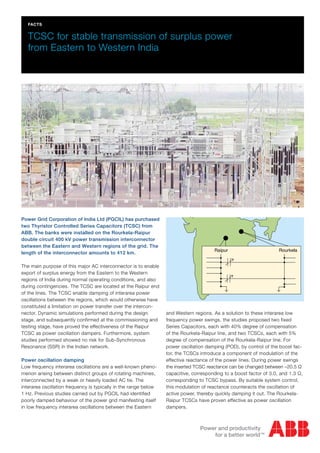
Power Grid Corporation of India Ltd (PGCIL) has purchased
two Thyristor Controlled Series Capacitors (TCSC) from
ABB. The banks were installed on the Rourkela-Raipur
double circuit 400 kV power transmission interconnector
between the Eastern and Western regions of the grid. The
length of the interconnector amounts to 412 km.
The main purpose of this major AC interconnector is to enable
export of surplus energy from the Eastern to the Western
regions of India during normal operating conditions, and also
during contingencies. The TCSC are located at the Raipur end
of the lines. The TCSC enable damping of interarea power
oscillations between the regions, which would otherwise have
constituted a limitation on power transfer over the intercon-
nector. Dynamic simulations performed during the design
stage, and subsequently confirmed at the commissioning and
testing stage, have proved the effectiveness of the Raipur
TCSC as power oscillation dampers. Furthermore, system
studies performed showed no risk for Sub-Synchronous
Resonance (SSR) in the Indian network.
Power oscillation damping
Low frequency interarea oscillations are a well-known pheno
menon arising between distinct groups of rotating machines,
interconnected by a weak or heavily loaded AC tie. The
interarea oscillation frequency is typically in the range below
1 Hz. Previous studies carried out by PGCIL had identified
poorly damped behaviour of the power grid manifesting itself
in low frequency interarea oscillations between the Eastern
and Western regions. As a solution to these interarea low
frequency power swings, the studies proposed two fixed
Series Capacitors, each with 40% degree of compensation
of the Rourkela-Raipur line, and two TCSCs, each with 5%
degree of compensation of the Rourkela-Raipur line. For
power oscillation damping (POD), by control of the boost fac-
tor, the TCSCs introduce a component of modulation of the
effective reactance of the power lines. During power swings
the inserted TCSC reactance can be changed between –20.5 Ω
capacitive, corresponding to a boost factor of 3.0, and 1.3 Ω,
corresponding to TCSC bypass. By suitable system control,
this modulation of reactance counteracts the oscillation of
active power, thereby quickly damping it out. The Rourkela-
Raipur TCSCs have proven effective as power oscillation
dampers.
two Thyristor Controlled Series Capacitors (TCSC) from ABB.
The banks were installed on the Rourkela-Raipur double circuit
400 kV power transmission interconnector between the
Eastern and Western regions of the grid. The length of the
interconnector amounts to 412 km. The main purpose of this
major AC interconnector is to enable export of surplus energy
from the Eastern to the Western regions of India during nor-
mal operating conditions, and also during contingencies. The
TCSC are located at the Raipur end of the lines.
The TCSC enable damping of interarea power oscillations
between the regions, which would otherwise have constituted
a limitation on power transfer over the interconnector.
Dynamic simulations performed during the design stage, and
subsequently confirmed at the commissioning and testing
stage, have proved the effectiveness of the Raipur TCSC as
power oscillation dampers.
Furthermore, system studies performed showed no risk for
Sub-Synchronous Resonance (SSR) in the Indian network.
2. ApplicationNoteA02-0185E,2011-03
Power oscillation damping
Main technical data (per one TCSC)
Parameter Fixed Segment TCSC Segment
Nominal system voltage 400 kV 400 kV
Rated line current 1550 A 1550 A
Line current overload, 30 minutes 2093 A 2093 A
Line current overload, 10 minutes 2325 A 2325 A
Physical capacitor reactance 54.7 Ω 6.83 Ω
Nominal capacitive boost factor 1.0 1.2
Boost factor range – 1.0–3.0
Rated capacitor reactive power 394 Mvar 71 Mvar
Rated capacitor bank voltage 84.8 kV 12.7 kV
Degree of compensation 40% 5% (@ 1.0 boost factor)
ZnO rating (incl. redundancy) 56 MJ 15 MJ
Single-line diagramThe graphs show a 1500 MW power transfer situation from
Eastern to Western regions, with a single-phase to ground
fault at Raipur s/s, cleared after 100 ms. A severe 0.35 Hz
power oscillation is triggered over the interconnector and ac-
tively damped out by means of the TCSC. The damping effect
of the TCSC is very distinct as shown in the “Power oscillation
damping“ graph to the right in this page.
Control and protection
The control system is based on the ABB MACH 2 concept,
which is a hardware and software system specifically devel-
oped for power applications. The MACH 2 system is built
around an industrial PC with add-in boards and I/O racks
connected through standard type field busses like CAN and
TDM. This has facilitated very high performance together with
small dimensions of the hardware. The TCSC can be control
led from two different locations. In the local control room there
is an Operator Work Station (OWS), based on a personal
computer. The TCSC can also be remotely controlled via a
Remote Work Station (RWS) from the substation control room.
Current measurements for the control and protection func-
tions are attained by use of Optical Current Transformers
(OCT). The OCT consists of a current transducer in the high
voltage busbar and an optical interface module in the control
room. Signal transmission between transducer and interface
is carried out by means of an optical fibre system including
platform links, high voltage signal columns and fibre optic ca-
bles. When power oscillations are detected, the POD control
function changes the reactance reference in such a way that
the power oscillations are damped out.
Thyristor valve
For controlled series capacitors, a thyristor valve is used for
controlling the apparent reactance of the capacitor. This is
done by adding charge to the capacitor through the thyristor
valve, i.e. boosting the capacitor voltage. The valve, located
on platform level, is water-cooled and equipped with two
vertically mounted, antiparallel stacks of thyristors. Each valve
string consists of 14 thyristors in series connection, each with
a wafer diameter of four inches. All communication between
valve and the ground mounted control system is done via fibre
optics. The thyristor valve is rated for a continuous current of
1850 A and a voltage of 12.7 kVrms. It is furthermore rated to
withstand short-circuit currents up to 55 kApeak, safely above
any plausible fault situation that the valve may have to endure
in operation.
For more information please contact:
ABB AB
FACTS
SE-721 64 Västerås, Sweden
Phone: +46 21 32 50 00
Fax: +46 21 32 48 10
www.abb.com/FACTS
FSC
2
2
-2
-4
-6
-8
time [s]
Xc[Ohm]
-10
-12
-14
-16
-18
0 5 10 15 20 25 30
TCSC
Power Transfer = 1500 MW
400 kV
1050
1000
950
900
850
800
750
700
650
600
550
time [s]
P[MW]
0 5 10 15 20 25 30
FSC
TCSC
Power Transfer = 1500 MW
FSC
2
2
-2
-4
-6
-8
time [s]
Xc[Ohm]
-10
-12
-14
-16
-18
0 5 10 15 20 25 30
TCSC
Power Transfer = 1500 MW
400 kV
1050
1000
950
900
850
800
750
700
650
600
550
time [s]
P[MW]
0 5 10 15 20 25 30
FSC
TCSC
Power Transfer = 1500 MW
FSC
2
2
-2
-4
-6
-8
time [s]
Xc[Ohm]
-10
-12
-14
-16
-18
0 5 10 15 20 25 30
TCSC
Power Transfer = 1500 MW
400 kV
1050
1000
950
900
850
800
750
700
650
600
550
time [s]
P[MW]
0 5 10 15 20 25 30
FSC
TCSC
Power Transfer = 1500 MW
TCSC reactance response
400 kV
![ApplicationNoteA02-0185E,2011-03
Power oscillation damping
Main technical data (per one TCSC)
Parameter Fixed Segment TCSC Segment
Nominal system voltage 400 kV 400 kV
Rated line current 1550 A 1550 A
Line current overload, 30 minutes 2093 A 2093 A
Line current overload, 10 minutes 2325 A 2325 A
Physical capacitor reactance 54.7 Ω 6.83 Ω
Nominal capacitive boost factor 1.0 1.2
Boost factor range – 1.0–3.0
Rated capacitor reactive power 394 Mvar 71 Mvar
Rated capacitor bank voltage 84.8 kV 12.7 kV
Degree of compensation 40% 5% (@ 1.0 boost factor)
ZnO rating (incl. redundancy) 56 MJ 15 MJ
Single-line diagramThe graphs show a 1500 MW power transfer situation from
Eastern to Western regions, with a single-phase to ground
fault at Raipur s/s, cleared after 100 ms. A severe 0.35 Hz
power oscillation is triggered over the interconnector and ac-
tively damped out by means of the TCSC. The damping effect
of the TCSC is very distinct as shown in the “Power oscillation
damping“ graph to the right in this page.
Control and protection
The control system is based on the ABB MACH 2 concept,
which is a hardware and software system specifically devel-
oped for power applications. The MACH 2 system is built
around an industrial PC with add-in boards and I/O racks
connected through standard type field busses like CAN and
TDM. This has facilitated very high performance together with
small dimensions of the hardware. The TCSC can be control
led from two different locations. In the local control room there
is an Operator Work Station (OWS), based on a personal
computer. The TCSC can also be remotely controlled via a
Remote Work Station (RWS) from the substation control room.
Current measurements for the control and protection func-
tions are attained by use of Optical Current Transformers
(OCT). The OCT consists of a current transducer in the high
voltage busbar and an optical interface module in the control
room. Signal transmission between transducer and interface
is carried out by means of an optical fibre system including
platform links, high voltage signal columns and fibre optic ca-
bles. When power oscillations are detected, the POD control
function changes the reactance reference in such a way that
the power oscillations are damped out.
Thyristor valve
For controlled series capacitors, a thyristor valve is used for
controlling the apparent reactance of the capacitor. This is
done by adding charge to the capacitor through the thyristor
valve, i.e. boosting the capacitor voltage. The valve, located
on platform level, is water-cooled and equipped with two
vertically mounted, antiparallel stacks of thyristors. Each valve
string consists of 14 thyristors in series connection, each with
a wafer diameter of four inches. All communication between
valve and the ground mounted control system is done via fibre
optics. The thyristor valve is rated for a continuous current of
1850 A and a voltage of 12.7 kVrms. It is furthermore rated to
withstand short-circuit currents up to 55 kApeak, safely above
any plausible fault situation that the valve may have to endure
in operation.
For more information please contact:
ABB AB
FACTS
SE-721 64 Västerås, Sweden
Phone: +46 21 32 50 00
Fax: +46 21 32 48 10
www.abb.com/FACTS
FSC
2
2
-2
-4
-6
-8
time [s]
Xc[Ohm]
-10
-12
-14
-16
-18
0 5 10 15 20 25 30
TCSC
Power Transfer = 1500 MW
400 kV
1050
1000
950
900
850
800
750
700
650
600
550
time [s]
P[MW]
0 5 10 15 20 25 30
FSC
TCSC
Power Transfer = 1500 MW
FSC
2
2
-2
-4
-6
-8
time [s]
Xc[Ohm]
-10
-12
-14
-16
-18
0 5 10 15 20 25 30
TCSC
Power Transfer = 1500 MW
400 kV
1050
1000
950
900
850
800
750
700
650
600
550
time [s]
P[MW]
0 5 10 15 20 25 30
FSC
TCSC
Power Transfer = 1500 MW
FSC
2
2
-2
-4
-6
-8
time [s]
Xc[Ohm]
-10
-12
-14
-16
-18
0 5 10 15 20 25 30
TCSC
Power Transfer = 1500 MW
400 kV
1050
1000
950
900
850
800
750
700
650
600
550
time [s]
P[MW]
0 5 10 15 20 25 30
FSC
TCSC
Power Transfer = 1500 MW
TCSC reactance response
400 kV](data:image/gif;base64,R0lGODlhAQABAIAAAAAAAP///yH5BAEAAAAALAAAAAABAAEAAAIBRAA7)