This document presents a simplified spatial modulation scheme for a multiple input single output orthogonal frequency division multiplexing (MISO-OFDM) system, highlighting improved throughput and efficiency compared to traditional OFDM systems. The proposed method uses a mathematical procedure for data and antenna activation, and MATLAB Simulink simulations validate its effectiveness by analyzing bit error rates against signal-to-noise ratios. The paper illustrates the integration of spatial modulation into OFDM to enhance data transmission through simultaneous activation of multiple antennas, aiming to meet the demands of future 5G and beyond communication systems.
![TELKOMNIKA Telecommunication, Computing, Electronics and Control
Vol. 18, No. 4, August 2020, pp. 1738~1745
ISSN: 1693-6930, accredited First Grade by Kemenristekdikti, Decree No: 21/E/KPT/2018
DOI: 10.12928/TELKOMNIKA.v18i4.13873 1738
Journal homepage: http://journal.uad.ac.id/index.php/TELKOMNIKA
A simplified spatial modulation MISO-OFDM scheme
Vian S. Al-Doori1
, Emad H. Al-Hemiary2
1
Al-Rafidain University College, Iraq
2
College of Information Engineering, Al-Nahrain University, Iraq
Article Info ABSTRACT
Article history:
Received Aug 12, 2019
Revised Mar 6, 2020
Accepted Apr 3, 2020
Index modulation is one of the promising techniques for future
communications systems due to many improvement over the classical
orthogonal frequency division multiplexing systems such as single RF chain,
increased throughput for the same modulation order, achieved tradeoff
between the efficiencies of the power and the spectral, and elimination
of inter-channel interference. Many forms of index modulation researches
exist where symbols are conveyed in antennas, subcarriers, time slots,
and the space-time matrix. Spatial modulation is one member of index
modulation family where symbols are conveyed in activating transmit/receive
antennas. In this paper, a modification to a standard multiple input
single output scheme by integrating spatial modulation using simplified
mathematical procedure is achieved. In the transmitter side, data and activation
symbols are distributed simultaneously using mathematical module and floor
functions. At the receiver, a simplified maximum likelihood detector is used
to obtain transmitted pair of symbols. To verify this, MATLAB simulink is
used to simulate a downlink system where spatial modulation is applied to
a base station. Results for different transmit antenna number and modulation
order are obtained in the form of bit error rate versus signal to noise ratio.
Keywords:
Index modulation
MISO-OFDM-SM
OFDM
Spatial modulation (SM)
This is an open access article under the CC BY-SA license.
Corresponding Author:
Vian S. Al-Doori,
Al-Rafidain University College,
Baghdad, Iraq.
Email: vian.kasim@ruc.edu.iq
1. INTRODUCTION
Increasing data rate, cell coverage, energy and spectral efficiency in wireless and mobile systems is
targeted by manufacturers in the current and future generations referred to as 5G and beyond [1-5].
The customer; on the other hand, is eager for better services either in the crowded or low density cells.
Therefore, researches recently proposes new technologies that enhance or even flips the traditional way of
implementing communication systems. As an example, exploiting other dimensions such as spatial
domain [6-10]. Since the application of OFDM (orthogonal frequency division multiplexing) technique,
wireless transceivers perform much better than traditional transceiver systems because of multicarrier over
single carrier advances. In traditional OFDM, data from subscribers is represented by subcarriers formed using
well known mapping techniques (PSK and QAM). In other words, the only way to transmit data symbols is
through OFDM subcarriers. The advances of data transmission in spatial domain enhances data rate by using
multiple antennas either in the transmitter (multiple input single output-MISO) or in the receiver (single input
multiple output-SIMO) or both (multiple input multiple output-MIMO). Therefore, spatial modulation (SM) is
a technique; proposed by [11], suppose to enhance performance by sending more symbols in selecting active
antenna (s). The transmitter operating SM divides data symbols into two parts: the first part are symbols](https://image.slidesharecdn.com/0613873-200717092113/85/A-simplified-spatial-modulation-MISO-OFDM-scheme-1-320.jpg)
![TELKOMNIKA Telecommun Comput El Control
A simplified spatial modulation MISO-OFDM scheme (Vian S. Al-Doori)
1739
modulated traditionally send using active antennas, while the second part are symbols conveyed in activating
those transmit antennas as shown in Figure 1. Convey of information bits in transmit antennas can be seen in
MIMO systems operating with subsets of two transmit antennas in each time slot. The latter technique is similar
to multiuser MIMO systems where different users are assigned to different transmitter sets and the receiver
equipment is composed of single or multiple antennas.
Figure 1. Concept of SM where extra symbols are conveyed in select active transmit antenna.
(a) One bit is used to set one active antenna from two transmit antennas
and (b) Two bits are used to set two active antennas from four transmit antennas
Many research articles address spatial modulation in terms of new technique, performance
enhancement, modification, and generalization for MIMO-OFDM systems (refer to [6, 12-14] for a survey
on SM theoretical analysis, receiver design, and other important issues). The work in this paper is closely
related to the following research papers in terms of using OFDM and single or multiple transmit antenna
activation. Luna-Rivera et al [15] do their work on the design of constellation in SM. They concludes that
transmitting the same data symbol from more than one antenna at a time enhances spectral efficiency but,
on the other hand, it degrades the bit error rate (BER) performance. Lin et al [16] worked on generalized SM
systems with ML (maximum liklehood) detector. They proposed a method to lower complexity in the detector
design by splitting the received symbols into two vectors index and symbol. Simulation results show that
the proposed schemes significantly outperform other existing methods while the detection complexity remains
low. Zhang et al [17] propose low complexity algorithms for SM detection by rearranging the detection order
of ML with respect to channel and received signal. They prove that BER performance is better than normal
MML (M-algorithm ML) but comparable complexity. Acar et al [18] concentrate their work on estimating
channel state information and how they use interpolation in SM-OFDM. The results show low estimation
complexity with least squares (LS) and low pass interpolation technique. Kumaravelu et al [19] propose
an 8X8 MIMO design with SM. They use adaptive mapping for antenna selection with ML scheme.
They claimed; using encoding, that their proposed scheme is a good candidate for IMT-2020 as well
as IEEE802.11ax based handheld devices with improved performance under line of sight channel. In this paper,
it is assumed that the transmitter is composed of multiple antennas selectively activated in each transmission
time slot. The system uses OFDM as the main subcarrier modulation technique. The rest of the paper is
organized as follows: Section 2, demonstrates the proposed system model of MISO-OFDM-SM. Section 3
presents the results and section 4 concludes the work in this paper.
2. MISO-OFDM-SM SYSTEM MODEL
This section present a proposed model for implementing SM in the transmitter of a typical baseband
OFDM system. To understand the latter one, Figure 2 shows a typical OFDM baseband tranciever system
without coding [20, 21]. According to literature, source data symbols are modulated using M-QAM (such as
4-QAM), paralleled, and the frequency domain output stream is fed to the IFFT block where pilot symbols are
inserted to enable receiver channel state information (CSI) estimation. Typically, zero padding stage enables
forming required FFT size. Therefore, an OFDM symbol is formed from data symbols (subcarriers), pilot
symbols, and zero pad symbols. Part of a time domain OFDM symbol (a tail) is replicated to the head of that
symbol to prevent intersymbol interference (Cyclic Prefix). At receiver side, CP is removed from time domain
signal, a reverse operation FFT takes place to transform back into frequency domain and pilot symbols are
extracted and compared to locally generated replicas to obtain the CSI. The previous operation is referred to](https://image.slidesharecdn.com/0613873-200717092113/85/A-simplified-spatial-modulation-MISO-OFDM-scheme-2-320.jpg)
![ ISSN: 1693-6930
TELKOMNIKA Telecommun Comput El Control, Vol. 18, No. 4, August 2020: 1738 - 1745
1740
as channel estimation and it is vital in performing symbol detection. Equilization compensates for subcarriers
change and ML detection [22] decides for transmitted symbols. Finally, the total number of bits conveyed in
this operation is log2 𝑀, where M the constellation order of the M-QAM demapper (demodulator). Modifying
the system shown in Figure 2 for SM requires adding extra OFDM and antenna blocks as shown in Figure 3.
Since SM conveys extra bits in activating transmitters that is, if 𝑁 𝑇 is number of transmit antenas then
a maximum of log2 𝑁 𝑇 bits are conveyed in this operation. Therefore, total number of transmitted bits become:
𝑇𝑟𝑎𝑛𝑠𝑚𝑖𝑡𝑡𝑒𝑑 𝑏𝑖𝑡𝑠 = log2 𝑀 + log2 𝑁 𝑇 = log2(𝑀 ∙ 𝑁 𝑇) (1)
Figure 2. Typical baseband OFDM tranceiver
Figure 3. MISO-OFDM-SM block diagram
As an example, using two transmit antennas and 4-QAM, a total of log2 4 + log2 2 = 2 + 1 = 3 𝑏𝑖𝑡𝑠
are transmitted in one transmit period result in enhancement of 50% over the traditional single antenna while
the same modulation order is preserved. The receiver; due to a fact that one (or a set of) transmit antenna (s)
are active in one transmit period, will try to detect the received bits. The complexity of achieving this detection
(or prediction) depeds on many factors related to the detection method itself, channel behavior, constellation
order, channel estimation accuracy, and number of bits conveyed in selecting transmit antennas (as the number
of spatial bits increase, complexity increases [23, 24]).
In Figure 3, Data bits are grouped into log2(𝑀 ∙ 𝑁 𝑇) bits where the least significant log2 𝑁 𝑇 used to
activate antennas and the rest of the grouped bits i.e. log2 𝑀 are used as subcarriers modulated symbols.
M-QAM modulator receives the latter bits and convert them to specified mapped symbols and 𝑁 𝑇 streams are
produced. A simple rule is introduced here for calculating the pair (𝑁𝑖𝑑𝑥, 𝐷𝑖𝑑𝑥) where 𝑁𝑖𝑑𝑥 is transmit antenna
index, 𝐷𝑖 is data symbol before SM, and 𝐷𝑖𝑑𝑥 is the transmitted (after SM) symbol:
{𝑁𝑖𝑑𝑥, 𝐷𝑖𝑑𝑥} = {
𝐷𝑖 𝑚𝑜𝑑 𝑁 𝑇 + 1 𝑆𝑒𝑙𝑒𝑐𝑡𝑖𝑛𝑔 𝑎𝑛𝑡𝑒𝑛𝑛𝑎 𝑖𝑛𝑑𝑒𝑥
𝑓𝑙𝑜𝑜𝑟(𝐷𝑖/ 𝑁 𝑇) 𝑇𝑟𝑎𝑛𝑠𝑚𝑖𝑡𝑡𝑖𝑛𝑔 𝑠𝑦𝑚𝑏𝑜𝑙
(2)
The receiver; equipped with a single antenna, receives a summed symbol from a flat faded channel 𝑯 in
the form given by:](https://image.slidesharecdn.com/0613873-200717092113/85/A-simplified-spatial-modulation-MISO-OFDM-scheme-3-320.jpg)
![TELKOMNIKA Telecommun Comput El Control
A simplified spatial modulation MISO-OFDM scheme (Vian S. Al-Doori)
1741
𝑦 = √ 𝑝𝑯𝒙 + 𝑛
𝑯 = [ℎ11 ℎ12 ⋯ ℎ1𝑁 𝑇]
𝒙 = [𝑥1 𝑥2
⋯ 𝑥 𝑁 𝑇] 𝑇
(3)
In (3), 𝑝 is the average signal to noise ratio measured at the receiver input and 𝑛 is an additive white
Gaussian noise power. Part of the received symbols are known to the receiver side (pilot symbols) used to estimate
the channel coefficients, therefore it is assumed; for simplicity, that channel estimation is performed using direct
LS (least squares). The estimated channel coefficients are used to equalize the received symbols and ML detector
jointly estimates the transmitted symbol and the antenna index using the following decision rules:
𝑆̂𝑖𝑑𝑥 = min
𝑖=1,2,..,𝑁 𝑇 𝑀−1
(|𝑌 − ℎ̂ 𝑍𝑖|
2
) (4)
𝐷̂ = 𝒁[(𝑆̂𝑖𝑑𝑥 − 1)𝑚𝑜𝑑𝑀 + 1] (5)
𝑁̂𝑖𝑑𝑥 = 𝑐𝑒𝑖𝑙 (
𝑆̂ 𝑖𝑑𝑥
𝑀
) (6)
Where:
𝑌 = 𝑅𝑒𝑐𝑒𝑖𝑣𝑒𝑑 𝑠𝑦𝑚𝑏𝑜𝑙, 𝐷̂ = 𝑑𝑒𝑡𝑒𝑐𝑡𝑒𝑑 𝑠𝑦𝑚𝑏𝑜𝑙, 𝑁̂𝑖𝑑𝑥 = 𝑑𝑒𝑡𝑒𝑐𝑡𝑒𝑑 𝑎𝑛𝑡𝑒𝑛𝑛𝑎 𝑖𝑛𝑑𝑒𝑥
ℎ̂ 𝑖𝑠 𝑡ℎ𝑒 𝑒𝑠𝑡𝑖𝑚𝑎𝑡𝑒 𝑜𝑓 ℎ
𝒁 = [𝑍1 𝑍2 ⋯ 𝑍 𝑀−1] = 𝑚𝑎𝑝𝑝𝑒𝑑 𝑠𝑒𝑡 𝑜𝑓 𝑎𝑙𝑙 𝑝𝑜𝑠𝑠𝑖𝑏𝑙𝑒 𝑡𝑟𝑎𝑛𝑠𝑚𝑖𝑡𝑡𝑒𝑑 𝑠𝑦𝑚𝑏𝑜𝑙𝑠
𝑆̂𝑖𝑑𝑥 𝑖𝑛𝑑𝑒𝑥 𝑜𝑓 𝑚𝑖𝑛𝑖𝑚𝑢𝑚 𝑣𝑎𝑙𝑢𝑒 𝑖𝑛 𝑎 𝑣𝑒𝑐𝑡𝑜𝑟 𝑜𝑓 𝑁 𝑇 𝑀 × 1
In (4), the operator 𝑚𝑖𝑛 selects the minimum value from a vector formed by subtracting received
symbol from all possible transmitted symbols. In (5) and (6) give simplified mathematical equations to find
the data symbol and the antenna number transmitted from. This will be explained later on using example.
Table 1 illustrates the use of (1) and (2) for different values of 𝑀 and 𝑁 𝑇.
Table 1. Proposed spatial mapping according to (1) and (2)
𝑁 𝑇 = 21
𝑁 𝑇 = 22
𝑁 𝑇 = 23
𝑁 𝑇 = 24
𝑀 = 21
𝐷𝑖 = 0,1,2,3
0,2 𝑜𝑛 𝐴𝑁𝑇1,
1,3 𝑜𝑛 𝐴𝑁𝑇2
N/A N/A N/A
𝑀 = 22
𝐷𝑖 = 0,1, … ,7
0,2,4,6 𝑜𝑛 𝐴𝑁𝑇1,
1,3,5,7 𝑜𝑛 𝐴𝑁𝑇2
𝐷𝑖 = 0,1, … ,15
0,4,8,12 𝑜𝑛 𝐴𝑁𝑇1
1,5,9,13 𝑜𝑛 𝐴𝑁𝑇2
2,6,10,14 𝑜𝑛 𝐴𝑁𝑇3
3,7,11,15 𝑜𝑛 𝐴𝑁𝑇4
N/A N/A
𝑀 = 23
𝐷𝑖 = 0,1, … ,15
0,2,4, … ,14 𝑜𝑛 𝐴𝑁𝑇1
1,3,5, … ,15 𝑜𝑛 𝐴𝑁𝑇2
𝐷𝑖 = 0,1, … ,31
0,4,8, … ,28 𝑜𝑛 𝐴𝑁𝑇1
1,5,9, … ,29 𝑜𝑛 𝐴𝑁𝑇2
2,6,10, … ,30 𝑜𝑛 𝐴𝑁𝑇3
3,7,11, … ,31 𝑜𝑛 𝐴𝑁𝑇4
𝐷𝑖 = 0,1, … ,63
0,8,16, … ,56 𝑜𝑛 𝐴𝑁𝑇1
1,9,17, … ,57 𝑜𝑛 𝐴𝑁𝑇2
⋮
7,15,23, … ,63 𝑜𝑛 𝐴𝑁𝑇8
N/A
𝑀 = 24
𝐷𝑖 = 0,1,2, … ,31
0,2,4, … ,14 𝑜𝑛 𝐴𝑁𝑇1
1,3,5, … ,15 𝑜𝑛 𝐴𝑁𝑇2
𝐷𝑖 = 0,1, … ,63
0,4,8, … ,60 𝑜𝑛 𝐴𝑁𝑇1
1,5,9, … ,61 𝑜𝑛 𝐴𝑁𝑇2
2,6,10, … ,62 𝑜𝑛 𝐴𝑁𝑇3
3,7,11, … ,63 𝑜𝑛 𝐴𝑁𝑇4
𝐷𝑖 = 0,1, … ,127
0,8,16, … ,120 𝑜𝑛 𝐴𝑁𝑇1
1,9,17, … ,121 𝑜𝑛 𝐴𝑁𝑇2
⋮
7,15,23, … ,127 𝑜𝑛 𝐴𝑁𝑇8
𝐷𝑖 = 0,1, … ,255
0,16,32… ,240 𝑜𝑛 𝐴𝑁𝑇1
1,17,33, … ,241 𝑜𝑛 𝐴𝑁𝑇2
⋮
31,47,63… ,255 𝑜𝑛 𝐴𝑁𝑇16
𝑀 = 2 𝑗
𝐷𝑖 = 0,1, . . , 2 𝑗+1
− 1
𝐷𝑖𝑑𝑥 = 𝑓𝑙𝑜𝑜𝑟(𝐷𝑖/2)
𝑁𝑖𝑑𝑥 = 𝐷𝑖 𝑚𝑜𝑑2 + 1
𝐷𝑖 = 0,1, . . , 2 𝑗+2
− 1
𝐷𝑖𝑑𝑥 = 𝑓𝑙𝑜𝑜𝑟(𝐷𝑖/4)
𝑁𝑖𝑑𝑥 = 𝐷𝑖 𝑚𝑜𝑑4 + 1
𝐷𝑖 = 0,1, . . , 2 𝑗+3
− 1
𝐷𝑖𝑑𝑥 = 𝑓𝑙𝑜𝑜𝑟(𝐷𝑖/8)
𝑁𝑖𝑑𝑥 = 𝐷𝑖 𝑚𝑜𝑑8 + 1
𝐷𝑖 = 0,1, . . , 2 𝑗+4
− 1
𝐷𝑖𝑑𝑥 = 𝑓𝑙𝑜𝑜𝑟(𝐷𝑖/16)
𝑁𝑖𝑑𝑥 = 𝐷𝑖 𝑚𝑜𝑑16 + 1
3. IMPLEMENTATION AND RESULTS
To obtain performance in terms of BER versus Signal to noise ratio (SNR), MATLAB SIMULINK is
used to build a baseband transceiver as shown in Figure 4. The design parameters for OFDM part follows
the IEEE802.16 standard listed in Table 2 [25]. For the pilot symbols, binary phase shift keying (BPSK) is used
to modulate orthogonal generated code using Hadamard code. The use of Hadamard is advantageous in activating
more than one transmit antennas at a time in case it is required. In Figure 4, total bits are 6 (𝑀 = 16 and 𝑁 𝑇 = 4)
which creates 360 × 6 = 2160 bits generated using Bernolli binary generator and converted into symbols using](https://image.slidesharecdn.com/0613873-200717092113/85/A-simplified-spatial-modulation-MISO-OFDM-scheme-4-320.jpg)
![TELKOMNIKA Telecommun Comput El Control
A simplified spatial modulation MISO-OFDM scheme (Vian S. Al-Doori)
1743
𝐴𝑠𝑠𝑢𝑚𝑖𝑛𝑔 𝑡ℎ𝑎𝑡 𝑎 𝑑𝑎𝑡𝑎 𝑓𝑟𝑎𝑚𝑒 𝑖𝑠 𝑔𝑒𝑛𝑒𝑟𝑎𝑡𝑒𝑑: 𝐷𝑎𝑡𝑎𝑓𝑟𝑎𝑚𝑒 = [5 2 6 0 4 6 3 0 6 4 7]
𝐷𝑖𝑑𝑥 = [2 1 3 0 2 3 1 0 3 2 3] 𝑎𝑛𝑑 𝑁𝑖𝑑𝑥 = [2 1 1 1 1 1 2 1 1 1 2]
𝐹𝑟𝑎𝑚𝑒 1: [0 1 3 0 2 3 0 0 3 2 0] →
𝑚𝑜𝑑𝑢𝑙𝑎𝑡𝑒𝑑 𝑓𝑟𝑎𝑚𝑒 1 = [𝟎 − 0.7071 − 0.7071i 0.7071 − 0.7071i − 0.7071 + 0.7071i 0.7071 +
0.7071i 0.7071 − 0.7071i 𝟎 − 0.7071 + 0.7071i 0.7071 − 0.7071i 0.7071 + 0.7071i 𝟎]
𝐹𝑟𝑎𝑚𝑒 2: [2, 0, 0,0,0, 0, 1, 0, 0, 0, 3] →
𝑚𝑜𝑑𝑢𝑙𝑎𝑡𝑒𝑑 𝐹𝑟𝑎𝑚𝑒 2
= [0.7071 + 0.7071i 𝟎 𝟎 𝟎 𝟎 𝟎 − 0.7071 − 0.7071i 𝟎 𝟎 𝟎 0.7071 − 0.7071i]
𝑝𝑖𝑙𝑜𝑡 𝑓𝑜𝑟 𝑓𝑟𝑎𝑚𝑒 1: [1 1] 𝑎𝑛𝑑 𝑝𝑖𝑙𝑜𝑡 𝑓𝑜𝑟 𝑓𝑟𝑎𝑚𝑒 2: [1 − 1]
ℎ = [0.6391 + 0.1991𝑖 1.3546 − 0.7361𝑖]
On the receiver side, the received data frame is (single antenna):
𝑅𝑒𝑐𝑒𝑖𝑣𝑒𝑑 𝑓𝑟𝑎𝑚𝑒 𝒀
= [1.3539 + 0.6591i − 0.3667 − 0.5401i 0.5478 − 0.2099i − 0.3400
+ 0.3209i 0.4844 + 0.6090i 0.8106 − 0.1779i − 1.6373 − 0.4004i − 0.6716
+ 0.4227i 0.6243 − 0.2995i 0.3468 + 0.5703i 0.3065 − 1.5442i]
𝑅𝑒𝑐𝑒𝑖𝑣𝑒𝑑 𝑝𝑖𝑙𝑜𝑡 𝑠𝑦𝑚𝑏𝑜𝑙𝑠 = [2.0086 − 0.6737i − 0.6207 + 0.7692i]
ℎ̂ = [0.6940 + 0.0477i 1.3147 − 0.7214i]
𝑂𝑟𝑖𝑔𝑖𝑛𝑎𝑙 𝑠𝑒𝑡 𝑜𝑓 𝑠𝑦𝑚𝑏𝑜𝑙𝑠: 𝒁
= [−0.7071 + 0.7071𝑖 − 0.7071 − 0.7071𝑖 0.7071 + 0.7071𝑖 0.7071 − 0.7071𝑖]
ℎ̂1 ∙ 𝒁 = [−0.5245 + 0.4570𝑖 − 0.4570 − 0.5245𝑖 0.4570 + 0.5245𝑖 0.5245 − 0.4570𝑖]
ℎ̂2 ∙ 𝒁 = [−0.4195 + 1.4397𝑖 − 1.4397 − 0.4195𝑖 1.4397 + 0.4195𝑖 0.4195 − 1.4397𝑖]
𝑇ℎ𝑒𝑛: ℎ̂ 𝒁 = [−0.5245 + 0.4570𝑖 − 0.4570 − 0.5245𝑖 0.4570 + 0.5245𝑖 0.5245 − 0.4570𝑖
− 0.4195 + 1.4397𝑖 − 1.4397 − 0.4195𝑖 1.4397 + 0.4195𝑖 0.4195 − 1.4397𝑖]
𝐴𝑝𝑝𝑙𝑦𝑖𝑛𝑔 𝐸𝑞𝑢𝑎𝑡𝑖𝑜𝑛 4 𝑓𝑜𝑟 𝑡ℎ𝑒 𝑓𝑖𝑟𝑠𝑡 𝑟𝑒𝑐𝑒𝑖𝑣𝑒𝑑 𝑠𝑦𝑚𝑏𝑜𝑙 (1.3539 + 0.6591i) 𝑦𝑖𝑒𝑙𝑑𝑠:
[3.5690; 4.6800; 0.8226; 1.9335; 3.7542; 8.9676; 𝟎. 𝟎𝟔𝟒𝟖; 5.2781]
𝑤𝑖𝑡ℎ 𝑚𝑖𝑛𝑖𝑚𝑢𝑚 𝑣𝑎𝑙𝑢𝑒 𝑜𝑓 0.0648 𝑙𝑜𝑐𝑎𝑡𝑒𝑑 𝑎𝑡 𝑝𝑜𝑠𝑖𝑡𝑖𝑜𝑛 7
→ 𝑓𝑟𝑜𝑚 𝐸𝑞𝑠. 5 𝑎𝑛𝑑 6, 𝑡ℎ𝑒 𝑖𝑛𝑑𝑒𝑥 𝑝𝑎𝑖𝑟 𝑜𝑓 𝑣𝑎𝑙𝑢𝑒𝑠 𝑎𝑟𝑒:
𝐷̂ = 𝒁[(𝑆̂𝑖𝑑𝑥 − 1)𝑚𝑜𝑑𝑀 + 1] = 𝒁[6𝑚𝑜𝑑4 + 1] = 𝒁[3] = 0.7071 + 0.7071𝑖
𝑁̂𝑖𝑑𝑥 = 𝑐𝑒𝑖𝑙 (
𝑆̂𝑖𝑑𝑥
𝑀
) = 𝑐𝑒𝑖𝑙 (
7
4
) = 𝑐𝑒𝑖𝑙(1.75) = 2
𝐹𝑟𝑜𝑚 𝑇𝑎𝑏𝑙𝑒 2 𝑎𝑏𝑜𝑣𝑒, 𝑡ℎ𝑒 𝑟𝑜𝑤 𝑐𝑜𝑟𝑟𝑒𝑠𝑝𝑜𝑛𝑑𝑖𝑛𝑔 𝑡𝑜 𝑎𝑛𝑡𝑒𝑛𝑛𝑎 𝑖𝑛𝑑𝑒𝑥 2 𝑎𝑛𝑑 𝑚𝑜𝑑𝑢𝑙𝑎𝑡𝑒𝑑 𝑠𝑦𝑚𝑏𝑜𝑙 0.7071 +
0.7071 𝑖 𝑔𝑖𝑣𝑒𝑠 𝑑𝑎𝑡𝑎 𝑠𝑦𝑚𝑏𝑜𝑙 5 𝑤ℎ𝑖𝑐ℎ 𝑐𝑜𝑛𝑐𝑙𝑢𝑑𝑒𝑠 𝑟𝑒𝑐𝑜𝑣𝑒𝑟𝑦 𝑜𝑓 𝑡𝑟𝑎𝑛𝑠𝑚𝑖𝑡𝑡𝑒𝑑 𝑠𝑦𝑚𝑏𝑜𝑙 𝑠𝑢𝑐𝑐𝑒𝑠𝑠𝑓𝑢𝑙𝑙𝑦.
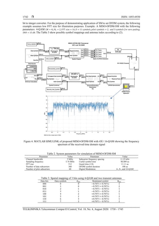
Figure 5 shows BER versus SNR for various number of transmit antennas and modulation order
using simulation parameters presented in Table 1. As modulation order increases, the separation between
modulated symbols gets closer which in turn makes the process of distinguishing them harder and needs more
enhanced methods.](https://image.slidesharecdn.com/0613873-200717092113/85/A-simplified-spatial-modulation-MISO-OFDM-scheme-6-320.jpg)
![ ISSN: 1693-6930
TELKOMNIKA Telecommun Comput El Control, Vol. 18, No. 4, August 2020: 1738 - 1745
1744
Figure 5. Performance evaluation of BER versus SNR for MISO-OFDM-SM system
with different transmit antennas an modulation order
4. CONCLUSION
In this paper, a simplified spatial modulation based OFDM is presented and simulated using MATLAB
SIMULINK. The proposed system; MISO-OFDM-SM is equipped with multiple transmit/single receive antennas
in which simple mathematical functions are used for assigning modulated simples to active tranmit antennas.
The proposed system assumes a receiver with maximum likelihood detector that discriminates and detects both
modulated and spatial symbols. It has been proven that the proposed method achieves the required task and further
ease receiver decision process. Furthermore, multiple input single output representing a base station downlink is
targeted in this work where the mobile client is equipped with single antenna.
REFERENCES
[1] E. Basar, M. Wen, R. Mesleh, M. Di Renzo, Y. Xiao, and H. Haas, “IEEE Access Special Section Editorial:
Index Modulation Techniques for Next-Generation Wireless Networks,” IEEE Access, vol. 6, no. 5, pp. 26452-26456,
June 2018.
[2] X. Cheng, M. Zhang, M. Wen, and L. Yang, “Index Modulation for 5G: Striving to Do More with Less,” IEEE Wirel.
Commun., vol. 25, no. 2, pp. 126-132, April 2018.
[3] X. Chen, D. Kwan Ng, W. Yu, E. Larsson, N. Al-Dhahir, and R. Schober "Massive access for 5G and beyond,"
arXiv:2002.03491 2020 [online] Available: http://arxiv.org/abs/2002.03491.
[4] E. Aydin, F. Cogen, and E. Basar, “Code-Index Modulation Aided Quadrature Spatial Modulation for High-Rate
MIMO Systems,” IEEE Trans. Veh. Technol., vol. 68, no. 10, pp. 10257-10261, Oct. 2019.
[5] M. Wen, X. Cheng, and L. Yang, “Index Modulation for 5G Wireless Communications,” Springer, 2017.
[6] M. Wen, B. Zheng, K. J. Kim, M. Di Renzo, T. Tsiftsis, “A Survey on Spatial Modulation in Emerging Wireless
Systems: Research Progresses and Applications,” IEEE J. Sel. Areas Commun., vol. 37, no. 9, pp. 1949-1972, 2019.
[7] D. Sinanović, G. Šišul, A. S. Kurdija, and Ž. Ilić, “Multiple transmit antennas for low PAPR spatial modulation in
SC-FDMA: single vs. multiple streams,” EURASIP J. Wirel. Commun. Netw., vol. 2020, no. 1, 2020.
[8] K. Humadi, A. Sulyman, and A. Alsanie, “Spatial Modulation Concept for Massive Multiuser MIMO Systems,”
Int. J. Antennas Propag., vol. 2014, ID 563273, pp. 1-9, 2014.
[9] S. Oladoyinbo, N. Pillay, and H. Xu, “Media-based single-symbol generalized spatial modulation,” Int. J. Commun.
Syst., vol. 32, no. 6, pp. e3909, Apr. 2019.
[10] S. Oladoyinbo, N. Pillay, and H. Xu, “Adaptive Quadrature Spatial Modulation,” IETE Tech. Rev., pp. 1-12,
October 2019.
[11] R. Mesleh, H. Haas, S. Sinanovic, C. W. Ahn and S. Yun, "Spatial Modulation," in IEEE Transactions on Vehicular
Technology, vol. 57, no. 4, pp. 2228-2241, July 2008.
[12] M. Di Renzo, H. Haas, and P. Grant, “Spatial Modulation for Multiple-Antenna Wireless Systems : A Survey,”
IEEE Commun. Mag., vol. 49, pp. 182–191, Dec. 2011.
[13] M. Di Renzo, H. Haas, A. Ghrayeb, S. Sugiura, and L. Hanzo, “Spatial Modulation for Generalized MIMO:
Challenges, Opportunities, and Implementation,” Proc. IEEE, vol. 102, pp. 56-103, Jan. 2014.](https://image.slidesharecdn.com/0613873-200717092113/85/A-simplified-spatial-modulation-MISO-OFDM-scheme-7-320.jpg)
![TELKOMNIKA Telecommun Comput El Control
A simplified spatial modulation MISO-OFDM scheme (Vian S. Al-Doori)
1745
[14] P. Yang, M. Di Renzo, Y. Xiao, S. Li and L. Hanzo, "Design Guidelines for Spatial Modulation," in IEEE
Communications Surveys & Tutorials, vol. 17, no. 1, pp. 6-26, Firstquarter 2015.
[15] J. M. Luna-Rivera, D. U. Campos-Delgado and M. G. Gonzalez-Perez, "Constellation design for spatial modulation,"
Procedia Technology 7, pp. 71-78, 2013.
[16] C. Lin, W. Wu and C. Liu, "Low-Complexity ML Detectors for Generalized Spatial Modulation Systems,"
in IEEE Transactions on Communications, vol. 63, no. 11, pp. 4214-4230, Nov. 2015.
[17] X. Zhang, G. Zhao, Q. Liu, N. Zhao, and M. Jin, “Enhanced M-algorithm-based maximum likelihood detectors for spatial
modulation,” AEU-International Journal of Electronics and Communications, vol. 70, no. 9, pp. 1361-1366, 2016.
[18] Y. Acar, H. Doğan, and E. Panayirci, “Pilot Symbol Aided Channel Estimation for Spatial Modulation-OFDM
Systems and its Performance Analysis with Different Types of Interpolations,” Wirel. Pers. Commun., vol. 94, no. 3,
pp. 1387-1404, 2017.
[19] V. B. Kumaravelu, G. Jaiswal, V. V. Gudla, G. Ramachandra Reddy, and A. Murugadass, “Modified Spatial
Modulation: An Alternate to Spatial Multiplexing for 5G-Based Compact Wireless Devices,” Arab. J. Sci. Eng.,
vol. 44, no. 8, pp. 6693-6709, 2019.
[20] H. Abdullah and R. Jaafr, “Comparative Study of Selected Subcarrier Index Modulation OFDM Schemes,”
TELKOMNIKA Indones. J. Electr. Eng., vol. 17, pp. 15-22, Feb. 2019.
[21] S. Alhloul and S. Yousef, “Uncoded OFDM system performance under Rayleigh fading condition,” Georg. Electron.
Sci. J. Comput. Sci. Telecommun., vol. 8, no. 1, pp. 51-60, Jan. 2006.
[22] M. Maleki, H. R. Bahrami and A. Alizadeh, "On MRC-Based Detection of Spatial Modulation," in IEEE Transactions
on Wireless Communications, vol. 15, no. 4, pp. 3019-3029, April 2016.
[23] N. Ishikawa, S. Sugiura, and L. Hanzo, “50 Years of Permutation, Spatial and Index Modulation: From Classic RF to
Visible Light Communications and Data Storage,” IEEE Commun. Surv. Tutorials, vol. 20, no. 3, pp. 1905-1938, 2018.
[24] M. Mohaisen, “Generalized Complex Quadrature Spatial Modulation,” Wirel. Commun. Mob. Comput., vol. 2019,
pp. 1-12, April 2019.
[25] IEEE Standard 802.16-2009, "Part 16: Air Interface for Broadband Wireless Access Systems," May 2009.
BIOGRAPHIES OF AUTHORS
Vian S. Al-Doori is a professor at Al-Rafidain university college and holds B.Sc., M.Sc.,
and Ph.D. in Modern Communication Systems from College of Engineering,
Al-Nahrain University 1998, 2002, and 2008 respectively. Her fields of interests include
MIMO and OFDM systems. She participated in many scientific activities including
establishment of new bachelor programs. Currently, she is working on latest MIMO
technologies that supports next generation communications.
Emad H. Al-Hemiary is a full professor at the college of Information Engineering of
Al-Nahrain University. He holds B.Sc. (1993), M.Sc. (1996) and a Ph.D. (2001) from
College of Engineering of Al-Nahrain University. He is specialized in Modern Networks,
Communication Systems, and Internet of Things. He is currently supervising research
students working on internet of things, blockchains, and v2x systems. He participated in
many scientific activities and published many research papers in his fields of interest.](https://image.slidesharecdn.com/0613873-200717092113/85/A-simplified-spatial-modulation-MISO-OFDM-scheme-8-320.jpg)


![MU- mimo [autosaved]](https://cdn.slidesharecdn.com/ss_thumbnails/massivemimoautosaved-190612174022-thumbnail.jpg?width=640&height=640&fit=bounds)