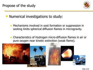
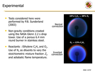
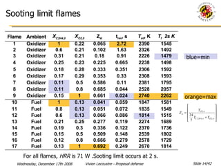
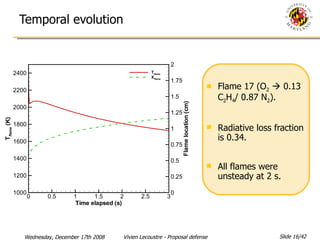
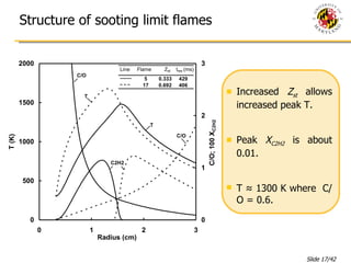
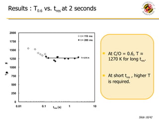
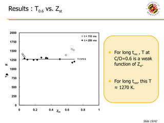
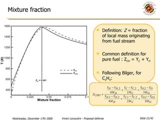
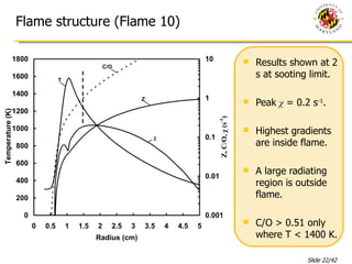
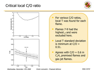
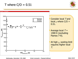
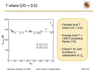
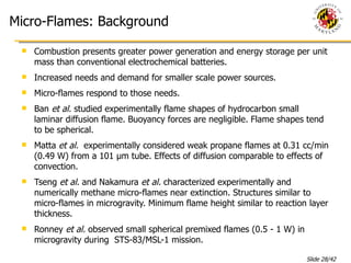
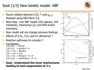
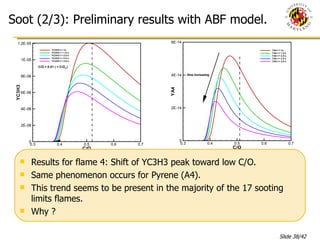
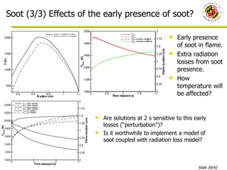
NUMERICAL INVESTIGATIONS OF GASEOUS SPHERICAL DIFFUSION FLAMES Advisory Committee: Assistant Professor  Peter B. Sunderland , Advisor and Chair Associate Professor  Gregory J. Jackson Associate Professor  André W. Marshall Associate Professor  Arnaud Trouvé Professor  James G. Quintiere , Dean’s representative By  Vivien Lecoustre, PhD student Dissertation Proposal
Acknowledgments This work was supported by NIST and NASA. Thanks to : B. W. Chao, R.L. Axelbaum, C.W. Moran, D.L. Urban, D.P. Stocker
Propose of the study Numerical investigations to study: Mechanisms involved in soot formation or suppression in sooting limits spherical diffusion flames in microgravity. Characteristics of Hydrogen micro-diffusion flames in air or pure oxygen near kinetic extinction (weak flame).
Presentation Outline Introduction: Spherical Diffusion Flames and Numerical Methods. Soot Formation in Ethylene Spherical Diffusion Flames. Weak Hydrogen Micro-Flames. Future Work and Management.
Why 1-D Spherical diffusion flame? Combustion is a succession of complex phenomena. Flame shape complicates the study of a single phenomenon (Flame stretch, 3-D velocity flow, etc…). Reducing dimensions facilitates study, establishment and use of “universal” model, free from the flame geometry (Ex: Flamelet model in turbulent flame). 1-D Spherical diffusion flame is a great potential vector to study fundamental phenomena (Soot, kinetic and radiative extinction, etc…).
Characteristics of Spherical Diffusion Flame Spherical diffusion flames are the only 1-D steady state diffusion flames with infinite boundary conditions possible. Burner generated gaseous diffusion flames can be steady state with an independent mass flow rate. Important past work on Spherical Diffusion flame: Steady state characteristics (Matalon  et al. ), Kinetic and Radiative extinction (Matalon, Chao, Liu), soot formation (Liu, Sunderland), Oscillations (Christiansen  et al. ). Reduced Damköhler number Adiabatic: Radiative loss: At Steady State: (Matalon  et al. )
Modeling Spherical Diffusion Flames (1/2) Use of SPHDIFF, 1-D laminar spherical diffusion flames code based on Sandia PREMIX code, from CHEMKIN package. Detailed chemistry kinetics and transport properties. Model steady-state and transient spherical diffusion flames. Use of a modified Newton method to solve problem.
Modeling Spherical Diffusion Flames (2/2) Species and heat diffusivities coefficient incremented by 30% to match experiments (Santa  et al. ). Boundary condition: Either adiabatic in temperature or fixed temperature. Allow backward species diffusion at burner surface. At outer boundary: fixed species mass fraction or adiabatic condition. Radiative model included. Optically thick model (Tse  et al. ). Discrete ordinates radiation model. Participation of CO 2 , H 2 O and CO. Kinetic models used:  GRI-Mech 3.0: 52 species, 325 reactions, C 1  and C 2  modeled.
Introduction: Spherical Diffusion Flames and Numerical methods. Soot Formation in Ethylene Spherical Diffusion flames. Weak Hydrogen Micro-Flames. Future Work and Management. Presentation Outline
Soot: Generalities Soot is a major pollutant. Appears in combustion of almost all hydrocarbon fuels. Solid compound made mostly of  carbon, presents in different sizes inside the flame (2 nm to 2 mm). Produced on the fuel side of the flame. Soot formation/oxidation process (Howard): Formation of soot precursors (PAH: Benzene and higher) Particle inception Surface growth and coagulation Particle oxidation (by OH, O and O 2 ) Importance of C 2 H 2 , C 3 H 3 , C 6 H 6  in soot particle inception and growth. Important Pathways to first ring: C 3 H 3  + C 3 H 3  -> Benzene + H+H C 3 H 3  + C 2 H 2  -> C 5 H 5 C 5 H 5  + CH 3   -> Benzene + H+H Growth of PAH by HACA mechanism: A i  + H    -> A i-  + H 2 A i-  + C 2 H 2   -> A i C 2 H 2 A i C 2 H 2  + C 2 H 2  -> A i+1
Soot: Background Competition between soot formation and oxidation. C/O ratio is about 0.6 for C 2 H 4  premixed flames at sooting limits (Glassman). C/O ratio relevant conserved scalar to sooting limits in diffusion flames. (Axelbaum and co-workers)  The minimum soot formation  T  in diffusion flames is 1250 – 1650 K (Glassman). Increased of  T  promotes soot presence in diffusion flame. Short time scale or high mixing rate can prevent soot formation. 17 sooting limits spherical C 2 H 4  microgravity flames were identified by Sunderland  et al .  These flames have a local critical C/O of about 0.6. Microgravity allows control over convection direction and residence time.
Objectives Investigate sooting limits of microgravity C 2 H 4  diffusion flames, emphasizing on elements of this new and unconventional hypothesis: local C/O atom ratio, local  T , and time scale   : residence time, local scalar dissipation rate . This numerical investigation uses detailed chemistry (GRI-Mech 3.0) and transport to elucidate past experiments.
Experimental Tests considered here were performed by P.B. Sunderland (2003) Non-gravity conditions created using the NASA Glenn 2.2 s drop tower. Use of a porous 6.4 mm round burner in stainless steel.  Reactants : Ethylene C 2 H 4  and O 2 . Use of N 2  as diluents to vary the stoichiometric mixture fraction  Z st  and adiabatic flame temperature. 18% C 2 H 4     28% O 2 O 2     13% C 2 H 4 Inverted  convection Normal  convection
blue=min orange=max For all flames,  HRR  is 71 W .Sooting limit occurs at 2 s. Sooting limit flames Flame Ambient X C2H4,0 X O2,0 Z st t res , s T ad ,  K T f   2s K 1 Oxidizer 1 0.22 0.065 2.72 2390 1545 2 Oxidizer 0.6 0.21 0.102 1.63 2326 1492 3 Oxidizer 0.31 0.21 0.18 0.91 2226 1479 4 Oxidizer 0.25 0.23 0.225 0.665 2238 1498 5 Oxidizer 0.18 0.28 0.333 0.351 2306 1592 6 Oxidizer 0.17 0.29 0.353 0.33 2308 1593 7 Oxidizer 0.11 0.5 0.586 0.11 2381 1795 8 Oxidizer 0.11 0.8 0.685 0.044 2528 2057 9 Oxidizer 0.15 1 0.661 0.024 2740 2262 10 Fuel 1 0.13 0.041 0.059 1847 1581 11 Fuel 0.8 0.13 0.051 0.072 1835 1549 12 Fuel 0.6 0.13 0.066 0.086 1814 1515 13 Fuel 0.21 0.25 0.277 0.119 2274 1689 14 Fuel 0.19 0.3 0.336 0.122 2370 1736 15 Fuel 0.15 0.5 0.509 0.148 2539 1802 16 Fuel 0.12 0.8 0.666 0.279 2578 1729 17 Fuel 0.13 1 0.692 0.249 2670 1814
Method Boundary temperature constant (Experiment did not show a significant variation of burner temperature). Use of GRI-Mech. 3.0. 200 to 300 mesh points. First compute the steady state solution of the flames for a small domain (1.2 cm) with adiabatic conditions in temperature at burner. No radiation losses. Simulate flame ignition. This steady state solution is then used as the starting point for the transient computation over an extend domain (100 cm) with radiative losses turned on. (Tse  et al. ) Output : solution at 2 s for all the 17 sooting limits flames. Look at the flame structure. Focus on C/O and temperature.
Temporal evolution Flame 17 (O 2     0.13 C 2 H 4 / 0.87 N 2 ). Radiative loss fraction is 0.34. All flames were unsteady at 2 s.
Structure of sooting limit flames Increased  Z st  allows increased peak T. Peak  X C2H2  is about 0.01. T ≈ 1300 K where  C/O = 0.6.
Results : T 0.6  vs. t res  at 2 seconds At C/O = 0.6, T ≈ 1270 K for long t res . At short t res  , higher T is required.
Results : T 0.6  vs. Z st For long t res  , T at C/O=0.6 is a weak function of Z st .  For long t res , this T ≈ 1270 K.
Time scale and scalar dissipation rate Previous results show that residence time shows trends. For inverse flame, residence time is not a good representative parameter of time scale.  Scalar dissipation rate: Scales an inverse characteristic mixing time. Need to know the Mixture fraction
Mixture fraction  Definition:  Z  = fraction of local mass originating from fuel stream Common definition for pure fuel : Z CH  = Y C  + Y H   Following Bilger, for C 2 H 4 :
Flame structure (Flame 10) Results shown at 2 s at sooting limit. Peak  χ  = 0.2 s -1 . Highest gradients are inside flame. A large radiating region is outside flame. C/O > 0.51 only where T < 1400 K.
Critical local C/O ratio For various C/O ratios, local T was found for each flame. Flames 7-9 had the highest  χ  and were excluded here. Local T standard deviation is minimum at C/O = 0.51. Agrees with C/O = 0.6 in C 2 H 4  premixed flames and gas jet flames.
T where C/O = 0.51 Consider local  T  and local  χ  where C/O = 0.51.  Average local  T  = 1400 K (excluding Flames 7-9). At high  χ , sooting limit requires higher local  T .
T where C/O = 0.51 Consider local T where C/O = 0.51.  Average local T = 1400 K (excluding Flames 7-9). Critical T for soot formation is independent of  Z st .
Conclusions A mixture fraction based on mass fractions of C, H, and O, atom is favored for the present flames. Soot formation in the present flames requires a local C/O    0.51 where  T     1400 K. These critical C/O and  T  are independent of convection direction,  X C2H4,0 ,  X O2,0 ,  Z st ,  t res ,  T ad ,  T peak , and (generally)  χ .   Flames with local  χ  > 2 s -1  require increased local temperatures to form soot.
Introduction: Spherical Diffusion Flames and Numerical Methods. Soot Formation in Ethylene Spherical Diffusion Flames. Weak Hydrogen Micro-Flames. Future Work and Management. Presentation Outline
Micro-Flames: Background Combustion presents greater power generation and energy storage per unit mass than conventional electrochemical batteries. Increased needs and demand for smaller scale power sources. Micro-flames respond to those needs. Ban  et al.  studied experimentally flame shapes of hydrocarbon small laminar diffusion flame. Buoyancy forces are negligible. Flame shapes tend to be spherical. Matta  et al.  experimentally considered weak propane flames at 0.31 cc/min (0.49 W) from a 101 µm tube. Effects of diffusion comparable to effects of convection. Tseng  et al.  and Nakamura  et al.  characterized experimentally and numerically methane micro-flames near extinction. Structures similar to micro-flames in microgravity. Minimum flame height similar to reaction layer thickness.  Ronney  et al.  observed small spherical premixed flames (0.5 - 1 W) in microgravity during  STS-83/MSL-1 mission.
Experimental results Reported by Butler  et al.   Hydrogen issuing from hypodermic tube (inner radius 75 µm) into quiescent air (left) and weakly conterflowing oxygen (right).  Reduction of mass flow rate until extinction. At extinction: H 2 /Air: H 2 /O 2 :
Objectives and method Numerical investigation of H 2 /Air and H 2 /O 2  diffusion flames at quenching limits: Seek for smallest mass flow rate sustaining a flame. Study the characteristics of those flame structures. Effects of burner size on flames near quenching. Effects of Damköhler number. Use SPHDIFF. Steady state modeling. Detailed chemistry based on GRI-Mech 3.0. Adiabatic conditions in temperature at the burner surface. Radiation neglected. Consider 4 burner radii: 3.175 mm, 300 µm, 75 µm and 1 µm.
H 2 /Air flame, r b  = 3.175 mm Moderate flow rate:  r b  = 3.175 mm T flame  = 2300 K r flame  = 22 cm HRR = 1275 W χ flame  = 5.2 10 -6  s -1 Large strong diffusion flame. Absence of leakage. Large Damköhler number. Greater peak corresponds to formation of water. Main contributors of HRR: R43: H+OH+M -> H 2 O+M (Exo.) R84: OH+H 2  -> H 2 O+H  (Exo.) R86: 2OH -> O+H 2 O  (Endo.) R38: H+O 2  -> O+OH  (Endo.) Smaller peak at lower T. Main contributors of HRR: R40: 2H+H 2  -> 2H 2   (Exo.) R41: 2H+H 2 O -> H 2 +H 2 O  (Exo.)
H 2 /Air flame, r b  = 75  μ m and 1  μ m  Low flow rate:  r b  = 75  μ m T flame  = 1290 K r flame = 200  μ m HRR = 0.41 W χ flame  = 0.98 s -1 Agreement with exp. Important presence of O 2  in the flame Small Damköhler number. Flame truncation due to burner presence. Single peak of HRR close to burner. Main contributors of HRR: R84: OH+H 2  -> H 2 O+H  (Exo.) R35: H+O 2 +H 2 O -> HO 2 +H 2 O(Exo.) R45: H+HO 2  -> O 2 +H 2   (Exo.) R46: H+HO 2  -> 2OH  (Exo.) R38: H+O 2  -> O+OH  (Endo.) High energy density : 8000 W/cm 3 r b  = 1  μ m T flame  = 1290 K r flame = 180  μ m HRR = 0.40 W χ flame  = 1.18 s -1 75  μ m burner 1  μ m burner
Effects of mass flow rate and burner size (1/2) For high  ṁ : T flame , X flame  independent of burner radii. Decreasing  ṁ  moves flame closer to burner. For  ṁ  low enough, burner prevents the flame to move closer, increasing leakage and reducing scalar dissipation rate. Kinetic extinction for T = 1300K. The 1  μ m burner can be taken as reference.
Effects of mass flow rate and burner size (2/2) For  χ flame  greater than 10 -3  s -1 , T flame  diminishes. Smaller flames present greater  χ flame .  Flame structure at backward branch presents significant oxidizer leakage.  Wide range of  χ flame  at extinction. T flame  = 1300 K at kinetic extinction.
Summary H 2  micro-flames weak flames observed numerically. With r b  = 75 μm, lowest mass flow rates of 3.65 μg/s (H 2 /air, 0.4 W) and 2.67 μg/s (H 2 /O 2 , 0.31 W). Weakest flame ever observed.  Good agreement with experimental measured quenching limits. Kinetic extinction numerically observed for adiabatic flames. T flame  = 1300 K at extinction for H 2 /Air. Larger burners prevent the flames from moving inward, resulting in truncated flames. Extinction at higher flow rates. High rates of oxidizer leakage through the flame. The main reactions contributing to heat release rate differ with the Damköhler number.
Introduction: Spherical Diffusion Flames and Numerical Methods. Soot Formation in Ethylene Spherical Diffusion Flame. Weak Hydrogen Micro-Flame. Future Work and Management. Presentation Outline
Soot (1/3) New kinetic model: ABF Found relation between C/O, T and  χ (C/O) . Realized using GRI-Mech 3.0. Next step : Use ABF model (101 species, 544 reactions), improving C 2 H 2  and PAH kinetic chemistry. New model will not change previous findings. Effects of C 2 H 2 , C 3 H 3  and A1 (Benzene) ? Reaction pathways to consider ? Candidates: Goal : Understand the inner mechanisms leading to soot suppression at 2 s. C 4 H 3 +C 2 H 2   -> Phenyl C 4 H 5 +C 2 H 2  -> Benzene + H C 3 H 3  + C 3 H 3  -> Benzene C 3 H 3  + C 2 H 2  -> C 5 H 5 C 5 H 5  + CH 3   -> Benzene + H + H C 5 H 5 +C 5 H 5   -> naphthalene + H + H
Soot (2/3): Preliminary results with ABF model. Results for flame 4: Shift of YC3H3 peak toward low C/O. Same phenomenon occurs for Pyrene (A4). This trend seems to be present in the majority of the 17 sooting limits flames. Why ?
Soot (3/3) Effects of the early presence of soot? Early presence of soot in flame. Extra radiation losses from soot presence. How temperature will be affected? Are solutions at 2 s sensitive to this early losses (“perturbation”)? Is it worthwhile to implement a model of soot coupled with radiation loss model?
Management : Soot project Evaluate flame response to different initial conditions. In parallel, completion of a first paper for publication. Based on the results of the evaluation, selection and implementation of a soot formation model for SPHDIFF, if needed. If soot model not useful, proceed directly with ABF model.  Investigate reactions pathways of major soot inceptors. Analysis of results and journal paper publication.
Management: H 2 /Air flames Compute reactions rate of progress for flames presented in Chapter 4. Model weak hydrogen flames in air and pure oxygen using 2-D code UNICORN. Analysis of results and journal paper publication.
Questions ? Thank you. And:

PhD Proposal - December 2008

  • 1.
    NUMERICAL INVESTIGATIONS OFGASEOUS SPHERICAL DIFFUSION FLAMES Advisory Committee: Assistant Professor Peter B. Sunderland , Advisor and Chair Associate Professor Gregory J. Jackson Associate Professor André W. Marshall Associate Professor Arnaud Trouvé Professor James G. Quintiere , Dean’s representative By Vivien Lecoustre, PhD student Dissertation Proposal
  • 2.
    Acknowledgments This workwas supported by NIST and NASA. Thanks to : B. W. Chao, R.L. Axelbaum, C.W. Moran, D.L. Urban, D.P. Stocker
  • 3.
    Propose of thestudy Numerical investigations to study: Mechanisms involved in soot formation or suppression in sooting limits spherical diffusion flames in microgravity. Characteristics of Hydrogen micro-diffusion flames in air or pure oxygen near kinetic extinction (weak flame).
  • 4.
    Presentation Outline Introduction:Spherical Diffusion Flames and Numerical Methods. Soot Formation in Ethylene Spherical Diffusion Flames. Weak Hydrogen Micro-Flames. Future Work and Management.
  • 5.
    Why 1-D Sphericaldiffusion flame? Combustion is a succession of complex phenomena. Flame shape complicates the study of a single phenomenon (Flame stretch, 3-D velocity flow, etc…). Reducing dimensions facilitates study, establishment and use of “universal” model, free from the flame geometry (Ex: Flamelet model in turbulent flame). 1-D Spherical diffusion flame is a great potential vector to study fundamental phenomena (Soot, kinetic and radiative extinction, etc…).
  • 6.
    Characteristics of SphericalDiffusion Flame Spherical diffusion flames are the only 1-D steady state diffusion flames with infinite boundary conditions possible. Burner generated gaseous diffusion flames can be steady state with an independent mass flow rate. Important past work on Spherical Diffusion flame: Steady state characteristics (Matalon et al. ), Kinetic and Radiative extinction (Matalon, Chao, Liu), soot formation (Liu, Sunderland), Oscillations (Christiansen et al. ). Reduced Damköhler number Adiabatic: Radiative loss: At Steady State: (Matalon et al. )
  • 7.
    Modeling Spherical DiffusionFlames (1/2) Use of SPHDIFF, 1-D laminar spherical diffusion flames code based on Sandia PREMIX code, from CHEMKIN package. Detailed chemistry kinetics and transport properties. Model steady-state and transient spherical diffusion flames. Use of a modified Newton method to solve problem.
  • 8.
    Modeling Spherical DiffusionFlames (2/2) Species and heat diffusivities coefficient incremented by 30% to match experiments (Santa et al. ). Boundary condition: Either adiabatic in temperature or fixed temperature. Allow backward species diffusion at burner surface. At outer boundary: fixed species mass fraction or adiabatic condition. Radiative model included. Optically thick model (Tse et al. ). Discrete ordinates radiation model. Participation of CO 2 , H 2 O and CO. Kinetic models used: GRI-Mech 3.0: 52 species, 325 reactions, C 1 and C 2 modeled.
  • 9.
    Introduction: Spherical DiffusionFlames and Numerical methods. Soot Formation in Ethylene Spherical Diffusion flames. Weak Hydrogen Micro-Flames. Future Work and Management. Presentation Outline
  • 10.
    Soot: Generalities Sootis a major pollutant. Appears in combustion of almost all hydrocarbon fuels. Solid compound made mostly of carbon, presents in different sizes inside the flame (2 nm to 2 mm). Produced on the fuel side of the flame. Soot formation/oxidation process (Howard): Formation of soot precursors (PAH: Benzene and higher) Particle inception Surface growth and coagulation Particle oxidation (by OH, O and O 2 ) Importance of C 2 H 2 , C 3 H 3 , C 6 H 6 in soot particle inception and growth. Important Pathways to first ring: C 3 H 3 + C 3 H 3 -> Benzene + H+H C 3 H 3 + C 2 H 2 -> C 5 H 5 C 5 H 5 + CH 3 -> Benzene + H+H Growth of PAH by HACA mechanism: A i + H -> A i- + H 2 A i- + C 2 H 2 -> A i C 2 H 2 A i C 2 H 2 + C 2 H 2 -> A i+1
  • 11.
    Soot: Background Competitionbetween soot formation and oxidation. C/O ratio is about 0.6 for C 2 H 4 premixed flames at sooting limits (Glassman). C/O ratio relevant conserved scalar to sooting limits in diffusion flames. (Axelbaum and co-workers) The minimum soot formation T in diffusion flames is 1250 – 1650 K (Glassman). Increased of T promotes soot presence in diffusion flame. Short time scale or high mixing rate can prevent soot formation. 17 sooting limits spherical C 2 H 4 microgravity flames were identified by Sunderland et al . These flames have a local critical C/O of about 0.6. Microgravity allows control over convection direction and residence time.
  • 12.
    Objectives Investigate sootinglimits of microgravity C 2 H 4 diffusion flames, emphasizing on elements of this new and unconventional hypothesis: local C/O atom ratio, local T , and time scale : residence time, local scalar dissipation rate . This numerical investigation uses detailed chemistry (GRI-Mech 3.0) and transport to elucidate past experiments.
  • 13.
    Experimental Tests consideredhere were performed by P.B. Sunderland (2003) Non-gravity conditions created using the NASA Glenn 2.2 s drop tower. Use of a porous 6.4 mm round burner in stainless steel. Reactants : Ethylene C 2 H 4 and O 2 . Use of N 2 as diluents to vary the stoichiometric mixture fraction Z st and adiabatic flame temperature. 18% C 2 H 4  28% O 2 O 2  13% C 2 H 4 Inverted convection Normal convection
  • 14.
    blue=min orange=max Forall flames, HRR is 71 W .Sooting limit occurs at 2 s. Sooting limit flames Flame Ambient X C2H4,0 X O2,0 Z st t res , s T ad , K T f 2s K 1 Oxidizer 1 0.22 0.065 2.72 2390 1545 2 Oxidizer 0.6 0.21 0.102 1.63 2326 1492 3 Oxidizer 0.31 0.21 0.18 0.91 2226 1479 4 Oxidizer 0.25 0.23 0.225 0.665 2238 1498 5 Oxidizer 0.18 0.28 0.333 0.351 2306 1592 6 Oxidizer 0.17 0.29 0.353 0.33 2308 1593 7 Oxidizer 0.11 0.5 0.586 0.11 2381 1795 8 Oxidizer 0.11 0.8 0.685 0.044 2528 2057 9 Oxidizer 0.15 1 0.661 0.024 2740 2262 10 Fuel 1 0.13 0.041 0.059 1847 1581 11 Fuel 0.8 0.13 0.051 0.072 1835 1549 12 Fuel 0.6 0.13 0.066 0.086 1814 1515 13 Fuel 0.21 0.25 0.277 0.119 2274 1689 14 Fuel 0.19 0.3 0.336 0.122 2370 1736 15 Fuel 0.15 0.5 0.509 0.148 2539 1802 16 Fuel 0.12 0.8 0.666 0.279 2578 1729 17 Fuel 0.13 1 0.692 0.249 2670 1814
  • 15.
    Method Boundary temperatureconstant (Experiment did not show a significant variation of burner temperature). Use of GRI-Mech. 3.0. 200 to 300 mesh points. First compute the steady state solution of the flames for a small domain (1.2 cm) with adiabatic conditions in temperature at burner. No radiation losses. Simulate flame ignition. This steady state solution is then used as the starting point for the transient computation over an extend domain (100 cm) with radiative losses turned on. (Tse et al. ) Output : solution at 2 s for all the 17 sooting limits flames. Look at the flame structure. Focus on C/O and temperature.
  • 16.
    Temporal evolution Flame17 (O 2  0.13 C 2 H 4 / 0.87 N 2 ). Radiative loss fraction is 0.34. All flames were unsteady at 2 s.
  • 17.
    Structure of sootinglimit flames Increased Z st allows increased peak T. Peak X C2H2 is about 0.01. T ≈ 1300 K where C/O = 0.6.
  • 18.
    Results : T0.6 vs. t res at 2 seconds At C/O = 0.6, T ≈ 1270 K for long t res . At short t res , higher T is required.
  • 19.
    Results : T0.6 vs. Z st For long t res , T at C/O=0.6 is a weak function of Z st . For long t res , this T ≈ 1270 K.
  • 20.
    Time scale andscalar dissipation rate Previous results show that residence time shows trends. For inverse flame, residence time is not a good representative parameter of time scale. Scalar dissipation rate: Scales an inverse characteristic mixing time. Need to know the Mixture fraction
  • 21.
    Mixture fraction Definition: Z = fraction of local mass originating from fuel stream Common definition for pure fuel : Z CH = Y C + Y H Following Bilger, for C 2 H 4 :
  • 22.
    Flame structure (Flame10) Results shown at 2 s at sooting limit. Peak χ = 0.2 s -1 . Highest gradients are inside flame. A large radiating region is outside flame. C/O > 0.51 only where T < 1400 K.
  • 23.
    Critical local C/Oratio For various C/O ratios, local T was found for each flame. Flames 7-9 had the highest χ and were excluded here. Local T standard deviation is minimum at C/O = 0.51. Agrees with C/O = 0.6 in C 2 H 4 premixed flames and gas jet flames.
  • 24.
    T where C/O= 0.51 Consider local T and local χ where C/O = 0.51. Average local T = 1400 K (excluding Flames 7-9). At high χ , sooting limit requires higher local T .
  • 25.
    T where C/O= 0.51 Consider local T where C/O = 0.51. Average local T = 1400 K (excluding Flames 7-9). Critical T for soot formation is independent of Z st .
  • 26.
    Conclusions A mixturefraction based on mass fractions of C, H, and O, atom is favored for the present flames. Soot formation in the present flames requires a local C/O  0.51 where T  1400 K. These critical C/O and T are independent of convection direction, X C2H4,0 , X O2,0 , Z st , t res , T ad , T peak , and (generally) χ . Flames with local χ > 2 s -1 require increased local temperatures to form soot.
  • 27.
    Introduction: Spherical DiffusionFlames and Numerical Methods. Soot Formation in Ethylene Spherical Diffusion Flames. Weak Hydrogen Micro-Flames. Future Work and Management. Presentation Outline
  • 28.
    Micro-Flames: Background Combustionpresents greater power generation and energy storage per unit mass than conventional electrochemical batteries. Increased needs and demand for smaller scale power sources. Micro-flames respond to those needs. Ban et al. studied experimentally flame shapes of hydrocarbon small laminar diffusion flame. Buoyancy forces are negligible. Flame shapes tend to be spherical. Matta et al. experimentally considered weak propane flames at 0.31 cc/min (0.49 W) from a 101 µm tube. Effects of diffusion comparable to effects of convection. Tseng et al. and Nakamura et al. characterized experimentally and numerically methane micro-flames near extinction. Structures similar to micro-flames in microgravity. Minimum flame height similar to reaction layer thickness. Ronney et al. observed small spherical premixed flames (0.5 - 1 W) in microgravity during STS-83/MSL-1 mission.
  • 29.
    Experimental results Reportedby Butler et al. Hydrogen issuing from hypodermic tube (inner radius 75 µm) into quiescent air (left) and weakly conterflowing oxygen (right). Reduction of mass flow rate until extinction. At extinction: H 2 /Air: H 2 /O 2 :
  • 30.
    Objectives and methodNumerical investigation of H 2 /Air and H 2 /O 2 diffusion flames at quenching limits: Seek for smallest mass flow rate sustaining a flame. Study the characteristics of those flame structures. Effects of burner size on flames near quenching. Effects of Damköhler number. Use SPHDIFF. Steady state modeling. Detailed chemistry based on GRI-Mech 3.0. Adiabatic conditions in temperature at the burner surface. Radiation neglected. Consider 4 burner radii: 3.175 mm, 300 µm, 75 µm and 1 µm.
  • 31.
    H 2 /Airflame, r b = 3.175 mm Moderate flow rate: r b = 3.175 mm T flame = 2300 K r flame = 22 cm HRR = 1275 W χ flame = 5.2 10 -6 s -1 Large strong diffusion flame. Absence of leakage. Large Damköhler number. Greater peak corresponds to formation of water. Main contributors of HRR: R43: H+OH+M -> H 2 O+M (Exo.) R84: OH+H 2 -> H 2 O+H (Exo.) R86: 2OH -> O+H 2 O (Endo.) R38: H+O 2 -> O+OH (Endo.) Smaller peak at lower T. Main contributors of HRR: R40: 2H+H 2 -> 2H 2 (Exo.) R41: 2H+H 2 O -> H 2 +H 2 O (Exo.)
  • 32.
    H 2 /Airflame, r b = 75 μ m and 1 μ m Low flow rate: r b = 75 μ m T flame = 1290 K r flame = 200 μ m HRR = 0.41 W χ flame = 0.98 s -1 Agreement with exp. Important presence of O 2 in the flame Small Damköhler number. Flame truncation due to burner presence. Single peak of HRR close to burner. Main contributors of HRR: R84: OH+H 2 -> H 2 O+H (Exo.) R35: H+O 2 +H 2 O -> HO 2 +H 2 O(Exo.) R45: H+HO 2 -> O 2 +H 2 (Exo.) R46: H+HO 2 -> 2OH (Exo.) R38: H+O 2 -> O+OH (Endo.) High energy density : 8000 W/cm 3 r b = 1 μ m T flame = 1290 K r flame = 180 μ m HRR = 0.40 W χ flame = 1.18 s -1 75 μ m burner 1 μ m burner
  • 33.
    Effects of massflow rate and burner size (1/2) For high ṁ : T flame , X flame independent of burner radii. Decreasing ṁ moves flame closer to burner. For ṁ low enough, burner prevents the flame to move closer, increasing leakage and reducing scalar dissipation rate. Kinetic extinction for T = 1300K. The 1 μ m burner can be taken as reference.
  • 34.
    Effects of massflow rate and burner size (2/2) For χ flame greater than 10 -3 s -1 , T flame diminishes. Smaller flames present greater χ flame . Flame structure at backward branch presents significant oxidizer leakage. Wide range of χ flame at extinction. T flame = 1300 K at kinetic extinction.
  • 35.
    Summary H 2 micro-flames weak flames observed numerically. With r b = 75 μm, lowest mass flow rates of 3.65 μg/s (H 2 /air, 0.4 W) and 2.67 μg/s (H 2 /O 2 , 0.31 W). Weakest flame ever observed. Good agreement with experimental measured quenching limits. Kinetic extinction numerically observed for adiabatic flames. T flame = 1300 K at extinction for H 2 /Air. Larger burners prevent the flames from moving inward, resulting in truncated flames. Extinction at higher flow rates. High rates of oxidizer leakage through the flame. The main reactions contributing to heat release rate differ with the Damköhler number.
  • 36.
    Introduction: Spherical DiffusionFlames and Numerical Methods. Soot Formation in Ethylene Spherical Diffusion Flame. Weak Hydrogen Micro-Flame. Future Work and Management. Presentation Outline
  • 37.
    Soot (1/3) Newkinetic model: ABF Found relation between C/O, T and χ (C/O) . Realized using GRI-Mech 3.0. Next step : Use ABF model (101 species, 544 reactions), improving C 2 H 2 and PAH kinetic chemistry. New model will not change previous findings. Effects of C 2 H 2 , C 3 H 3 and A1 (Benzene) ? Reaction pathways to consider ? Candidates: Goal : Understand the inner mechanisms leading to soot suppression at 2 s. C 4 H 3 +C 2 H 2 -> Phenyl C 4 H 5 +C 2 H 2 -> Benzene + H C 3 H 3 + C 3 H 3 -> Benzene C 3 H 3 + C 2 H 2 -> C 5 H 5 C 5 H 5 + CH 3 -> Benzene + H + H C 5 H 5 +C 5 H 5 -> naphthalene + H + H
  • 38.
    Soot (2/3): Preliminaryresults with ABF model. Results for flame 4: Shift of YC3H3 peak toward low C/O. Same phenomenon occurs for Pyrene (A4). This trend seems to be present in the majority of the 17 sooting limits flames. Why ?
  • 39.
    Soot (3/3) Effectsof the early presence of soot? Early presence of soot in flame. Extra radiation losses from soot presence. How temperature will be affected? Are solutions at 2 s sensitive to this early losses (“perturbation”)? Is it worthwhile to implement a model of soot coupled with radiation loss model?
  • 40.
    Management : Sootproject Evaluate flame response to different initial conditions. In parallel, completion of a first paper for publication. Based on the results of the evaluation, selection and implementation of a soot formation model for SPHDIFF, if needed. If soot model not useful, proceed directly with ABF model. Investigate reactions pathways of major soot inceptors. Analysis of results and journal paper publication.
  • 41.
    Management: H 2/Air flames Compute reactions rate of progress for flames presented in Chapter 4. Model weak hydrogen flames in air and pure oxygen using 2-D code UNICORN. Analysis of results and journal paper publication.
  • 42.