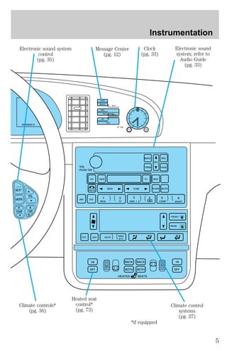
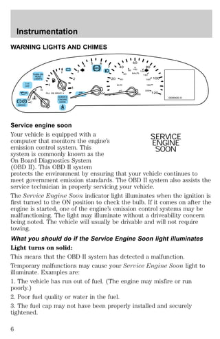
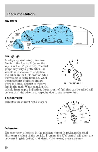
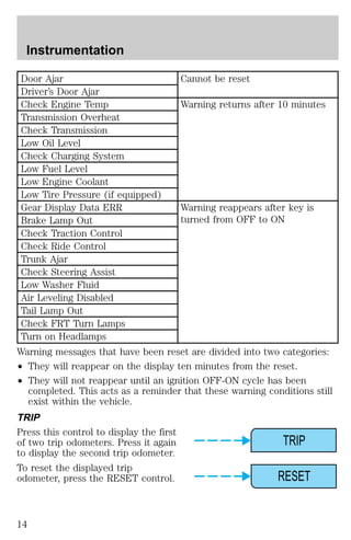
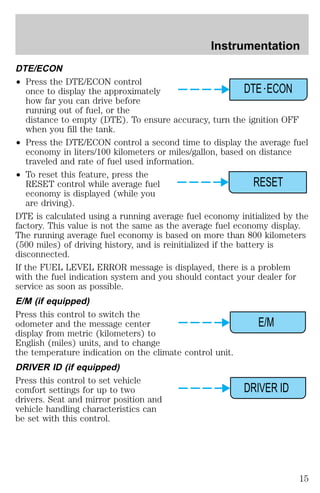
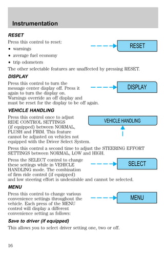
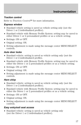
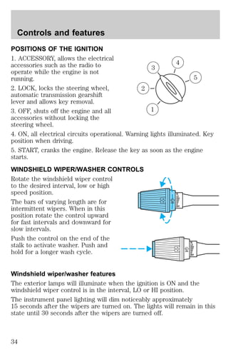
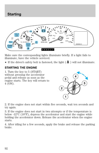
The document provides an overview of instrumentation and controls for a vehicle. It describes the various gauges, lights, messages and controls displayed on the instrument panel. This includes warning lights for issues like low fuel, descriptions of the speedometer and other gauges, as well as how to use controls to view trip information or vehicle system statuses on the electronic message center.


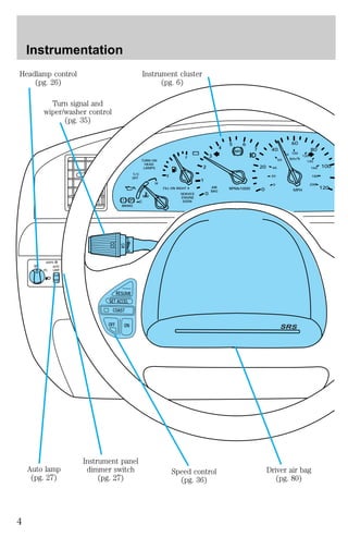
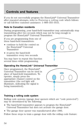
![Controls and features
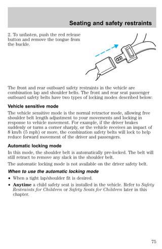
5. Release the switch, then slowly press it down again. Press the switch
repeatedly until the correct zone setting for your geographic location is
displayed on the upper right corner of the mirror.
6. To exit the zone setting mode, release pressure from the switch for
greater than two seconds.
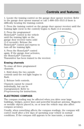
Compass calibration adjustment
Perform this adjustment in an open area free from steel structures and
high voltage lines.
For optimum calibration, turn off all electrical accessories (heater/air
conditioning, wipers, etc.) and make sure all vehicle doors are shut.
1. Start the vehicle.
2. Locate the compass module
mounted on the base of mirror.
3. Insert an appropriate diameter
rod (paperclip) into the left switch
access hole underneath the compass
module.
4. Gently press the switch for 1 to
2 seconds until CAL and a direction
are displayed on the upper right
corner of the mirror. (To exit CAL
before performing a compass adjustment, turn the ignition to OFF.)
5. Release pressure from the switch.
6. Slowly drive the vehicle in a circle (less than 5 km/h [3 mph]) until
the CAL indicator turns off. This will take up to five circles to complete
calibration.
7. The compass is now calibrated.
The compass display will remain on for approximately 40-45 minutes
after the ignition key is removed. The battery saver will then shut off the
display.
AUTOMATIC DIMMING INSIDE REAR VIEW MIRROR
The electronic day/night mirror will change from the normal state to the
non-glare state when bright lights (glare) reach the mirror. When the
mirror detects bright light from front or behind, it will automatically
adjust to minimize glare.
57](https://image.slidesharecdn.com/98continental-140905151929-phpapp01/85/98-continental-57-320.jpg)
![Seating and safety restraints
section in the Instrumentation chapter. Routine maintenance of the air
bag is not required.
A difficulty with the system is indicated by one or more of the following:
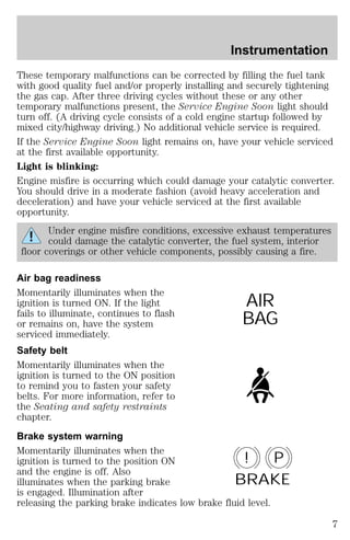
² The readiness light will either
flash or stay lit.
² The readiness light will not
illuminate immediately after
ignition is turned on.
AIR
BAG
² A series of five beeps will be heard. The tone pattern will repeat
periodically until the problem and light are repaired.
If any of these things happen, even intermittently, have the SRS serviced
at your dealership or by a qualified technician immediately. Unless
serviced, the system may not function properly in the event of a
collision.
Disposal of air bags and air bag equipped vehicles
For disposal of air bags or air bag equipped vehicles, see your local
dealership or qualified technician. Air bags MUST BE disposed of by
qualified personnel.
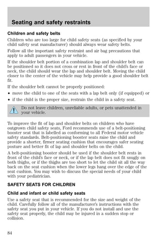
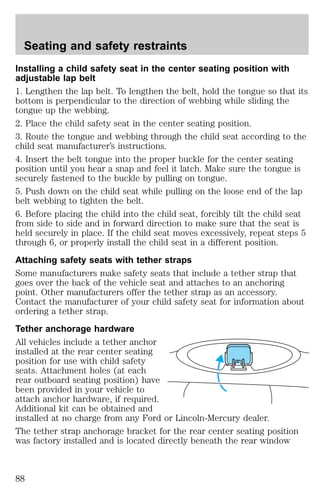
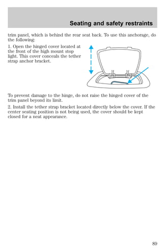
SAFETY RESTRAINTS FOR CHILDREN
Important child restraint precautions
You are required by law to use safety restraints for children in the U.S.
and Canada. If small children ride in your vehicle (generally children who
are four years old or younger and who weigh 18 kg [40 lbs] or less), you
must put them in safety seats made especially for children. Check your
local and state or provincial laws for specific requirements regarding the
safety of children in your vehicle.
Never let a passenger hold a child on his or her lap while the
vehicle is moving. The passenger cannot protect the child from
injury in a collision.
Always follow the instructions and warnings that come with any infant or
child restraint you might use.
When possible, place children in the rear seat of your vehicle. Accident
statistics suggest that children are safer when properly restrained in the
rear seating positions than in the front seating position.
83](https://image.slidesharecdn.com/98continental-140905151929-phpapp01/85/98-continental-83-320.jpg)
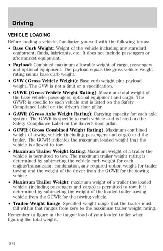
![Driving
Do not exceed the GVWR or the GAWR specified on the Safety
Compliance Certification Label.
Do not use replacement tires with lower weight capacities than the
originals because they may lower the vehicle’s GVWR and GAWR
limitations. Replacement tires with a higher weight limit than the
originals do not increase the GVWR and GAWR limitations.
TRAILER TOWING
Your vehicle is classified as a light duty towing vehicle. Refer to the
following chart for towing limits:
Towing class Light duty
Maximum gross trailer weight 454/907 kg (1 000/2 000 lbs.)*
Maximum tongue load 45/91 kg (100/200 lbs.)
Engine 4.6L
Hitch design Load carrying type
Trailer-tow package option Not required
* Vehicle speed should not exceed 72 km/h (45 mph) when towing on
grades. Limit maximum gross trailer weight to 454 kg (1 000 lbs.) and
maximum tongue load to 45 kg (100 lbs.): (1) when you are towing a
trailer on steep hills or on moderate hills for distances longer than
8 km (5 miles) or more and; (2) on very hot days (when the
temperature is above 38°C [100°F]).
Your vehicle does not come from the factory fully equipped to tow.
However, you can contact your local Lincoln dealer to get the proper
towing equipment. Do not tow a trailer until your vehicle has been
driven at least 3 200 km (2 000 miles).
Towing a trailer places an additional load on your vehicle’s engine,
transmission, brakes, tires and suspension. Inspect these components
carefully after towing.
Do not tow a trailer when using a temporary spare tire.
The amount of weight your loaded trailer should be no more than 907 kg
(2 000 lbs.).
105](https://image.slidesharecdn.com/98continental-140905151929-phpapp01/85/98-continental-105-320.jpg)
![Driving
FUEL CONSUMPTION
Fuel economy can be improved by avoiding:
² lack of regular, scheduled maintenance.
² excessive speed.
² rapid acceleration.
² extended idle.
CHECKING YOUR HIGHWAY FUEL ECONOMY USING THE
ELECTRONIC MESSAGE CENTER DISPLAY
The following procedure will allow you to accurately monitor your actual
highway fuel economy. Since this procedure requires the vehicle speed
control system to be set to highway speeds, it must be run only on
suitable roadways where long distance speed control can be safely
maintained.
You may notice gradual improvement in fuel economy over the course of
your vehicle’s break-in period (approximately 1 600 kilometers
[1 000 miles]).
1. Set the speed control. Refer to Speed control in the Controls and
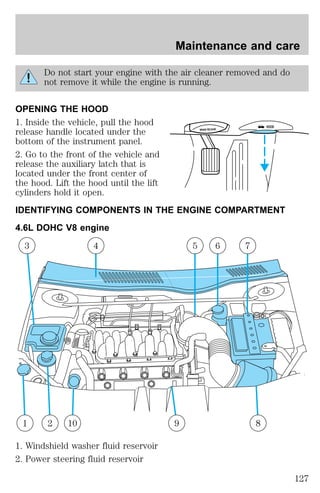
features chapter.
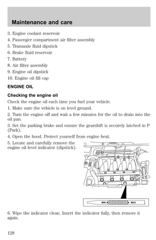
2. Press the Distance to Empty
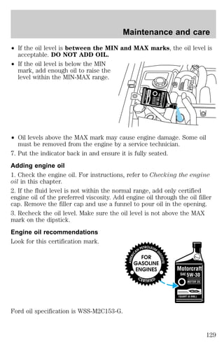
(DTE) Economy (ECON) control
DTE ECON
until “Average Miles per Gallon” is
displayed.
3. Press the RESET control to clear
the system memory.
RESET
² Actual highway fuel economy is
now displayed. This current average measure will change as the
speed control system changes the engine speed to maintain a constant
vehicle speed. This is most noticeable in hilly environments.
It is important to press the RESET control after setting the speed
control to get accurate highway fuel economy readings.
108](https://image.slidesharecdn.com/98continental-140905151929-phpapp01/85/98-continental-108-320.jpg)
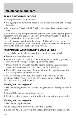
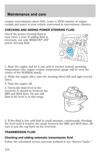
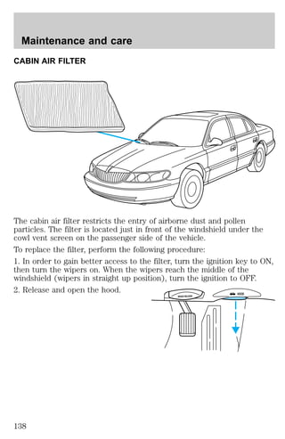
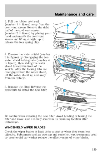
![Maintenance and care
2. When the engine is cool, wrap a thick cloth around the cap. Slowly
turn cap counterclockwise.
3. Step back while the pressure releases.
4. When you are sure that all the pressure has been released, turn it
counterclockwise and remove it.
Use Ford Premium Cooling System Fluid E2FZ-19549–AA (in Canada,
Motorcraft CXC-8–B) or an equivalent premium engine coolant that
meets Ford specification ESE-M97B44–A. Ford Premium Engine Coolant
is an optimized formula that will protect all metals and rubber elastomers
used in Ford cooling systems for four years or 80,000 km (50,000 miles).
Do not use alcohol or methanol antifreeze or any engine coolants mixed
with alcohol or methanol antifreeze. Do not use supplemental coolant
additives in your vehicle. These additives may harm your engine cooling
system. The use of an improper coolant may void your warranty of your
vehicle’s engine cooling system.
Recycled engine coolant
Ford Motor Company recommends that Ford and Lincoln-Mercury
dealers use recycled engine coolant produced by Ford-approved
processes. Not all coolant recycling processes produce coolant which
meets Ford specification ESE-M97B44–A, and use of such coolant may
harm engine and cooling system components.
Always dispose of used automotive fluids in a responsible manner.
Follow your community’s regulations and standards for recycling and
disposing of automotive fluids.
Coolant refill capacity
To find out how much fluid your vehicle’s cooling system can hold, refer
to Refill capacities in the Capacities and specifications chapter.
Have your dealer check the engine cooling system for leaks if you have
to add more than a liter (quart) of engine coolant per month.
Severe winter climate
If you drive in extremely cold climates (less than –36°C [–34°F]), it may
be necessary to increase the coolant concentration above 50%. Refer to
the chart on the coolant container to ensure the coolant concentration in
your vehicle is such that the coolant will not freeze at the temperature
level in which you drive during winter months. Never increase the engine
133](https://image.slidesharecdn.com/98continental-140905151929-phpapp01/85/98-continental-133-320.jpg)