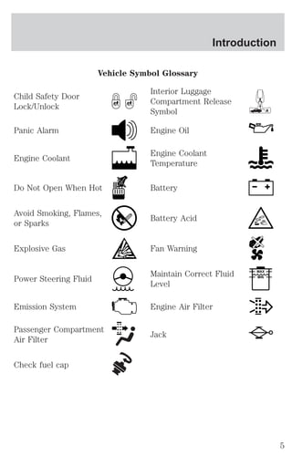
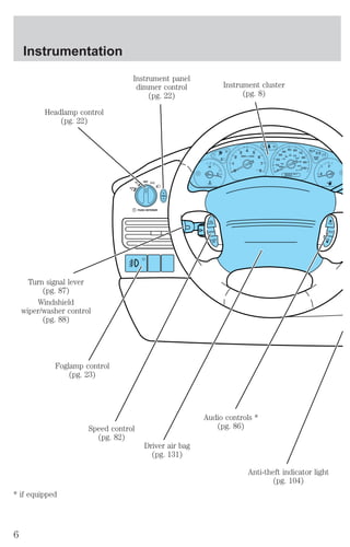
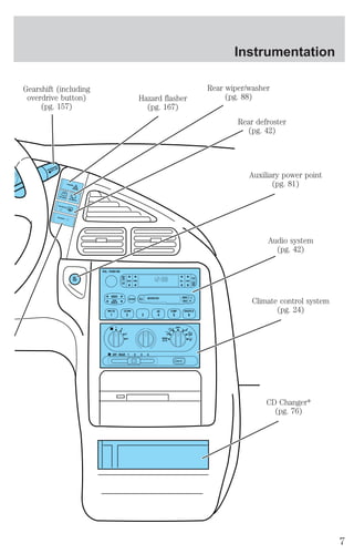
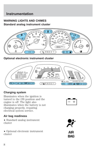
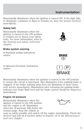
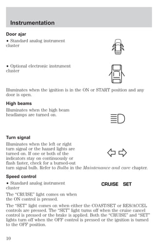
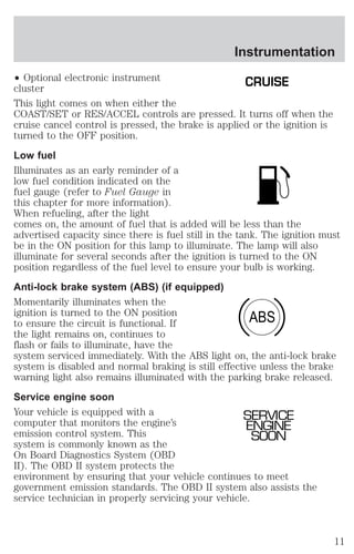
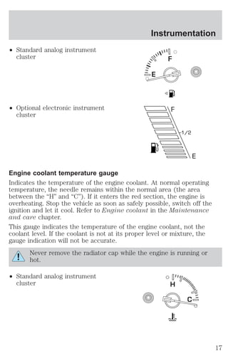
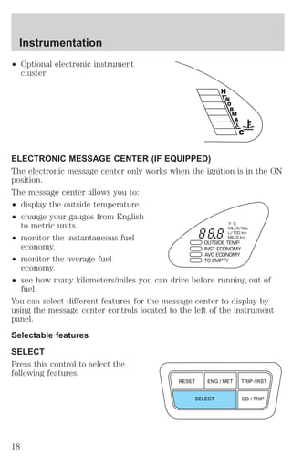
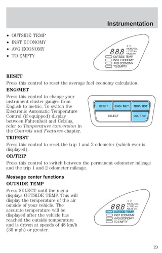
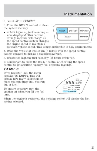
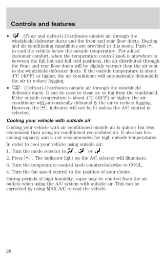
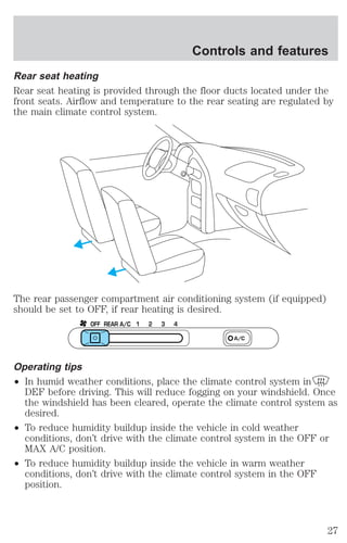
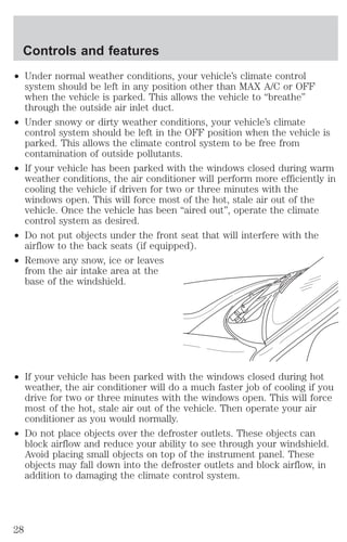
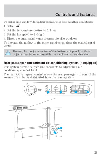
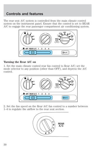
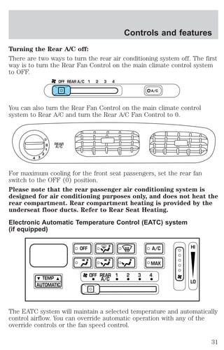
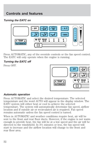
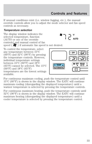
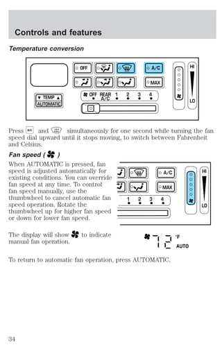
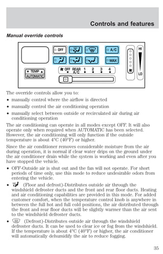
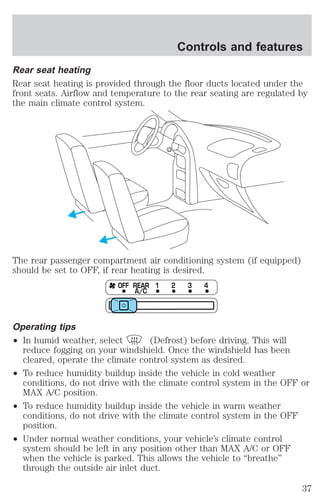
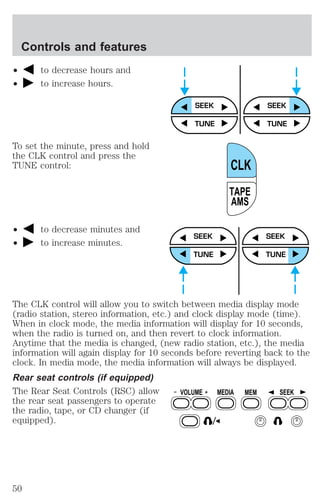
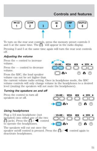
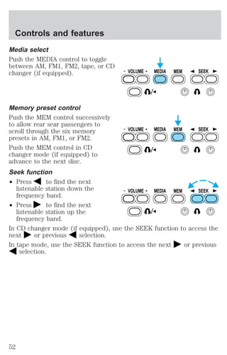
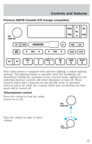
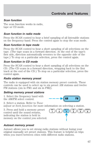
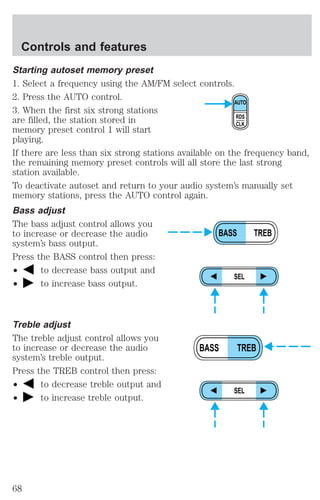
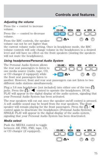
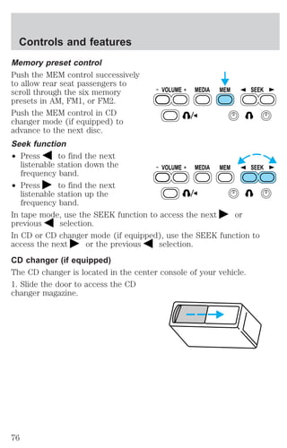
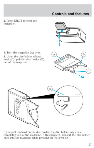
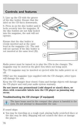
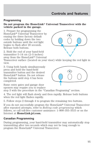
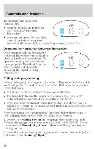
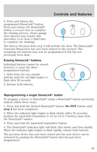
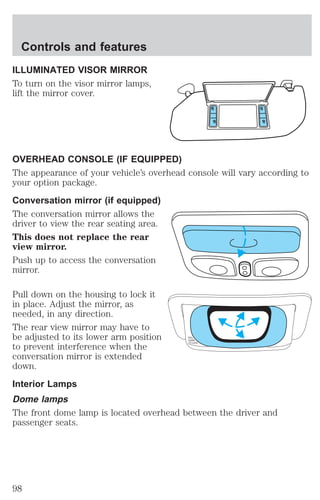
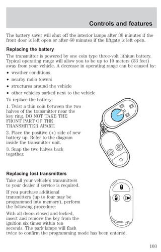
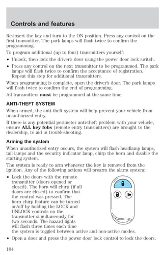
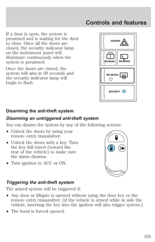
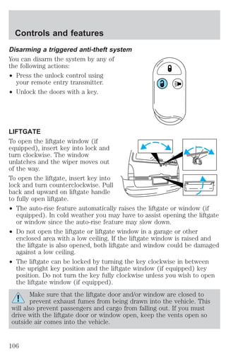
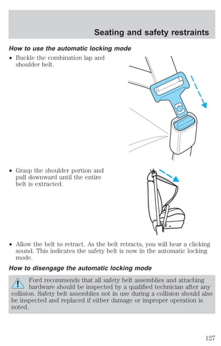
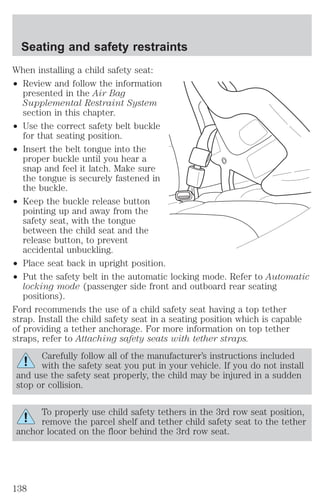
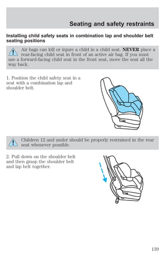
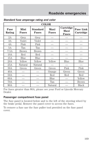
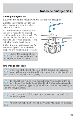
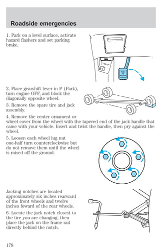
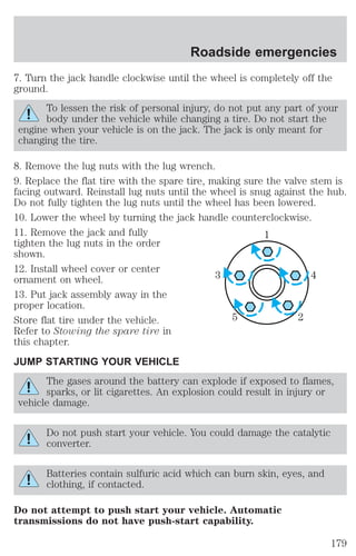
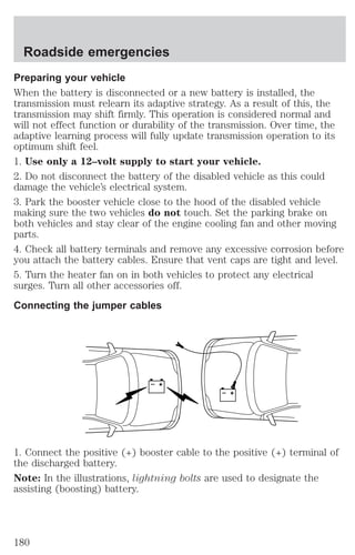
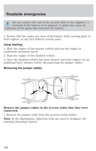
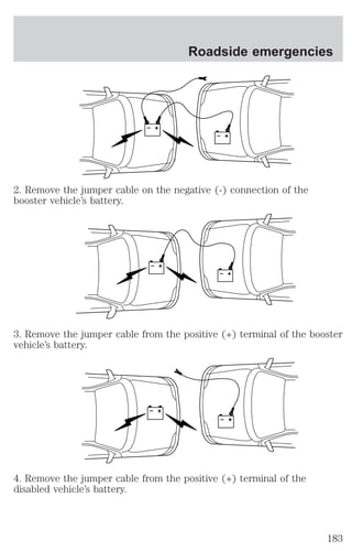
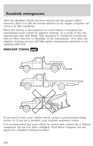
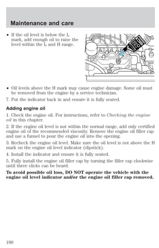
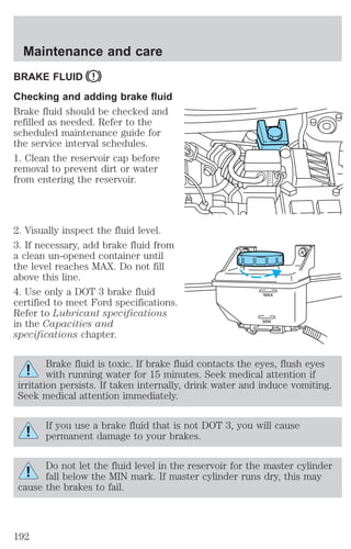
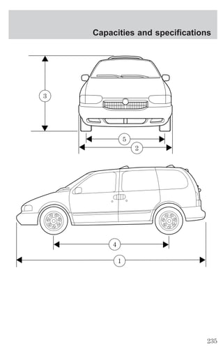
This document provides an overview of instrumentation and controls for a vehicle. It includes descriptions of common dashboard indicators, such as warning lights for low fuel, oil pressure issues, and more. Gauge clusters with tachometers, speedometers, odometers are depicted and explained. The document also outlines different controls like the gearshift, audio system, climate controls and their locations. Safety features including airbags and safety belt warnings are referenced.
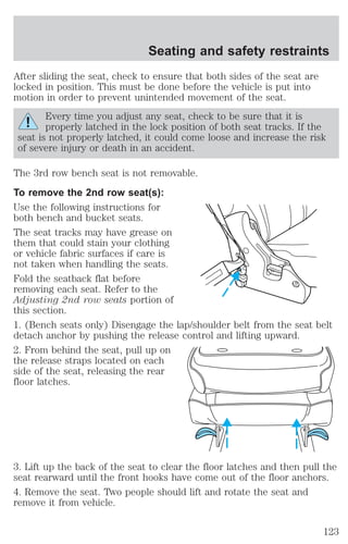
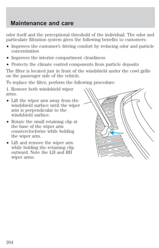
![Instrumentation
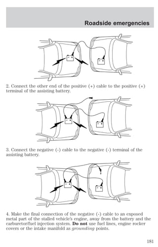
INST ECONOMY
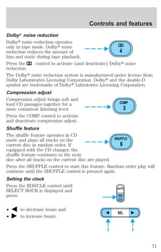
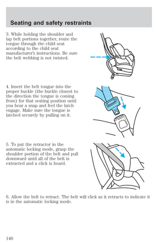
Press SELECT until the menu
displays INST ECONOMY. This will
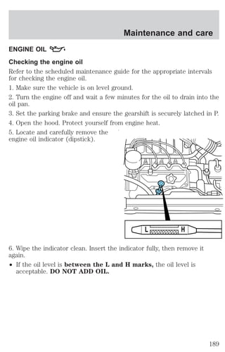
display your fuel economy in
liters/100 km or miles/gallon based
on the type of traffic you are in.
Your vehicle must be moving to
calculate instantaneous fuel
economy. When your vehicle is not
moving, this function shows 99 L/100km or 0 MILES/GAL. Instantaneous
fuel economy cannot be reset.
AVG ECONOMY
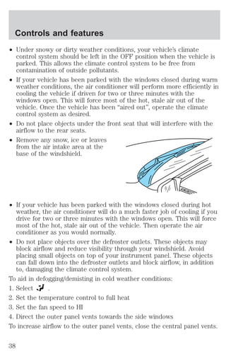
Press SELECT until the menu
displays AVG ECONOMY. This will
display your average fuel economy
in liters/100 km or miles/gallon.
If you calculate your average fuel
economy by dividing liters of fuel
used by 100 kilometers traveled
(miles traveled by gallons used),
your figure may be different than displayed for the following reasons:
² your vehicle was not perfectly level during fill-up
² differences in the automatic shut-off points on the fuel pumps at
service stations
°F °C
MILES/GAL
L/100 km
MILES km
OUTSIDE TEMP
INST ECONOMY
AVG ECONOMY
TO EMPTY
°F °C
MILES/GAL
L/100 km
MILES km
OUTSIDE TEMP
INST ECONOMY
AVG ECONOMY
TO EMPTY
² rounding of the displayed values to the nearest 0.1 liter (gallon)
Checking your highway fuel economy using the electronic
message center display
Use the following procedure will allow you to accurately monitor your
actual highway fuel economy. This procedure requires the vehicle speed
control system to be set to highway speeds and must be run only on
suitable roadways where long distance speed control can be safely
maintained.
You may notice gradual improvement in fuel economy over the course of
your vehicle’s break-in period (approximately 1 600 kilometers [1 000
miles]).
1. Set the speed control. Refer to Speed control in the Controls and
features chapter.
20](https://image.slidesharecdn.com/01villager-140831143535-phpapp01/85/01-villager-20-320.jpg)
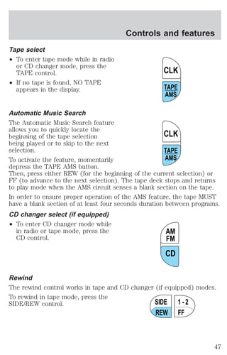
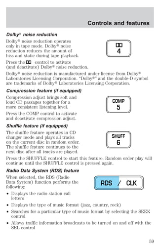
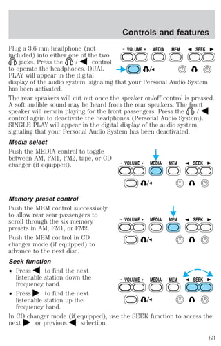
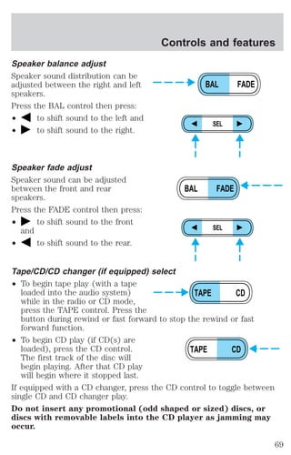
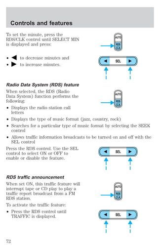
![² To begin CD play (if CD[s] are
loaded), press the CD control.
The first track of the disc will
begin playing. After that, CD play
will begin where it stopped last.
Do not insert any promotional (odd shaped or sized) discs, or discs
with removable labels into the CD player as jamming may occur.
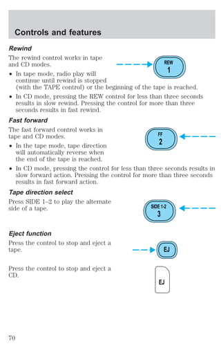
Rewind
The rewind control works in tape
and CD changer modes (if
equipped).
² In tape mode, radio play will
continue until rewind is stopped
(with the TAPE or FF control) or the beginning of the tape is reached.
² In CD changer mode, pressing the REW control for less than three
seconds results in slow rewind. Pressing the control for more than
three seconds results in fast rewind.
Fast forward
The fast forward control works in
tape and CD changer modes (if
equipped).
² In the tape mode, tape direction
will automatically reverse when the end of the tape is reached.
² In CD changer mode, pressing the control for less than three seconds
results in slow forward action. Pressing the control for more than
three seconds results in fast forward action.
Tape direction select
Press SIDE 1–2 to play the alternate
side of a tape.
Eject function
Press the control to stop and eject a
tape.
CD TAPE
REW
1
FF
2
SIDE 1-2
3
EJ
Controls and features
58](https://image.slidesharecdn.com/01villager-140831143535-phpapp01/85/01-villager-58-320.jpg)
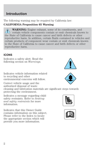
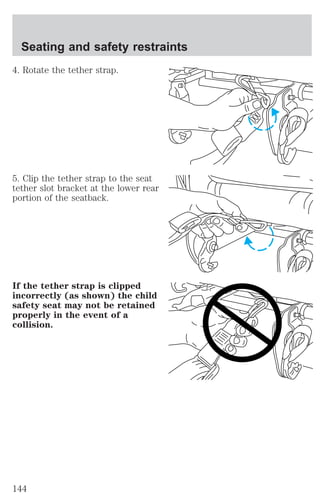
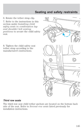
![Seating and safety restraints
If any of these things happen, even intermittently, have the SRS serviced
at your dealership or by a qualified technician immediately. Unless
serviced, the system may not function properly in the event of a
collision.
Disposal of air bags and air bag equipped vehicles (including
pretensioners)
For disposal of air bags or air bag equipped vehicles, see your local
dealership or qualified technician. Air bags MUST BE disposed of by
qualified personnel.
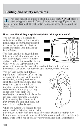
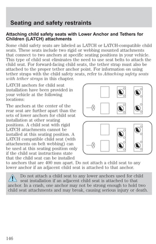
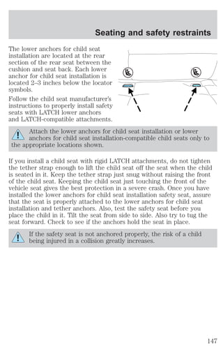
SAFETY RESTRAINTS FOR CHILDREN
See the following sections for directions on how to properly use safety
restraints for children. Also see Air Bag Supplemental Restraint
System (SRS) in this chapter for special instructions about using air
bags.
Important child restraint precautions
You are required by law to use safety restraints for children in the U.S.
and Canada. If small children ride in your vehicle (generally children who
are four years old or younger and who weigh 18 kg [40 lbs] or less), you
must put them in safety seats made especially for children. Check your
local and state or provincial laws for specific requirements regarding the
safety of children in your vehicle.
Never let a passenger hold a child on his or her lap while the
vehicle is moving. The passenger cannot protect the child from
injury in a collision.
Always follow the instructions and warnings that come with any infant or
child restraint you might use.
When possible, always place children under age 12 in the rear seat of
your vehicle. Accident statistics suggest that children are safer when
properly restrained in the rear seating positions than in the front seating
position.
Children and safety belts
If the child is the proper size, restrain the child in a safety seat.
Children who are too large for child safety seats (as specified by your
child safety seat manufacturer) should always wear safety belts.
136](https://image.slidesharecdn.com/01villager-140831143535-phpapp01/85/01-villager-136-320.jpg)

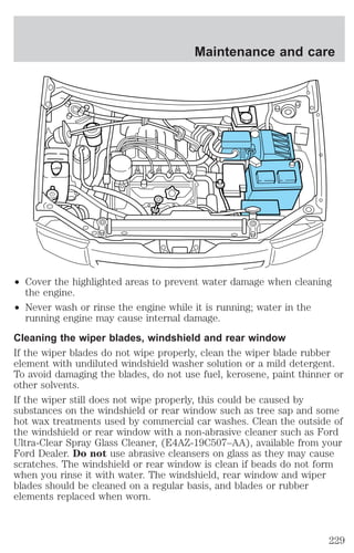
![Maintenance and care
Severe climates
If you drive in extremely cold climates (less than –36° C [–34° F]):
² it may be necessary to increase the coolant concentration
above 50%.
² NEVER increase the coolant concentration above 60%.
² increased engine coolant concentrations above 60% will
decrease the overheat protection characteristics of the engine
coolant and may cause engine damage.
² refer to the chart on the coolant container to ensure the
coolant concentration in your vehicle will provide adequate
freeze protection at the temperatures in which you drive in the
winter months.
If you drive in extremely hot climates:
² it is still necessary to maintain the coolant concentration
above 40%.
² NEVER decrease the coolant concentration below 40%.
² decreased engine coolant concentrations below 40% will
decrease the corrosion protection characteristics of the engine
coolant and may cause engine damage.
² decreased engine coolant concentrations below 40% will
decrease the freeze protection characteristics of the engine
coolant and may cause engine damage.
² refer to the chart on the coolant container to ensure the
coolant concentration in your vehicle will provide adequate
protection at the temperatures in which you drive.
Vehicles driven year-round in non-extreme climates should use a 50/50
mixture of engine coolant and distilled water for optimum cooling system
and engine protection.
CHECKING AND ADDING POWER STEERING FLUID
Check the power steering fluid. Refer to the scheduled maintenance
guide for the service interval schedules. If adding fluid is necessary, use
only MERCONt ATF.
197](https://image.slidesharecdn.com/01villager-140831143535-phpapp01/85/01-villager-197-320.jpg)
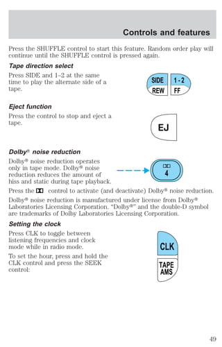
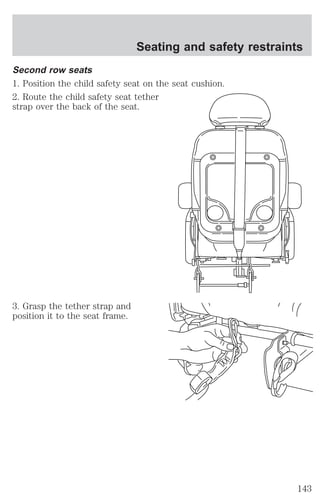
![1. Start the engine and let it run
until it reaches normal operating
temperature (the engine coolant
temperature gauge indicator will be
near the center of the normal area
between H and C).
2. While the engine idles, turn the
steering wheel left and right several
times.
3. Turn the engine off.
4. Check the fluid level in the
reservoir. It should be between the
MIN and MAX lines. Do not add
fluid if the level is in this range.
5. If the fluid is low, add fluid in
small amounts, continuously
checking the level until it reaches
MAX
MIN
the range between the MIN and
MAX lines. Be sure to put the cap
back on the reservoir.
TRANSMISSION FLUID
Checking automatic transmission fluid
Refer to your scheduled maintenance guide for scheduled intervals for
fluid checks and changes. Your transaxle does not consume fluid.
However, the fluid level should be checked if the transaxle is not working
properly, i.e., if the transaxle slips or shifts slowly or if you notice some
sign of fluid leakage.
Automatic transmission fluid expands when warmed. To obtain an
accurate fluid check, drive the vehicle until it is warmed up
(approximately 30 km [20 miles]). If your vehicle has been
operated for an extended period at high speeds, in city traffic
during hot weather or pulling a trailer, the vehicle should be
turned off for about 30 minutes to allow fluid to cool before
checking.
1. Drive the vehicle 30 km (20 miles) or until it reaches normal operating
temperature.
2. Park the vehicle on a level surface and engage the parking brake.
Maintenance and care
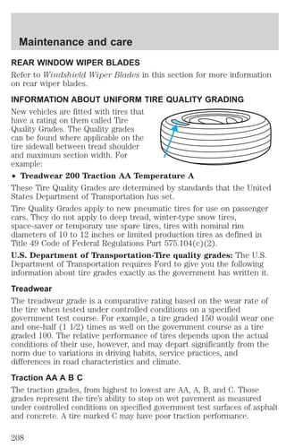
198](https://image.slidesharecdn.com/01villager-140831143535-phpapp01/85/01-villager-198-320.jpg)
![Maintenance and care
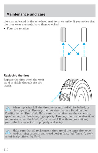
3. With the parking brake engaged and your foot on the brake pedal,
start the engine and move the gearshift lever through all of the gear
ranges. Allow sufficient time for each gear to engage.
4. Latch the gearshift lever in P (Park) and leave the engine running.
5. Remove the dipstick, wiping it clean with a clean, dry lint free rag. If
necessary, refer to Identifying components in the engine compartment
in this chapter for the location of the dipstick.
6. Install the dipstick making sure it is fully seated in the filler tube.
7. Remove the dipstick and inspect the fluid level. The fluid should be in
the designated areas for normal operating temperature.
Low fluid level
Do not drive the vehicle if the fluid
level is at the bottom of the dipstick
and the outside temperatures are
above 10°C (50°F).
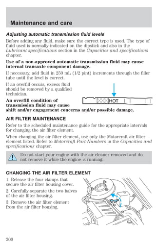
HOT
Correct fluid level
The transmission fluid should be checked at normal operating
temperatures 66°C-77°C (150°F-170°F) on a level surface. The normal
operating temperature can be reached after approximately 30 km (20
miles) of driving.
The transmission fluid should be in
this range if at normal operating
temperature (66°C-77°C
HOT
[150°F-170°F]).
High fluid level
Fluid levels above the safe range
may result in transaxle failure. An
overfill condition of transmission
fluid may cause shift and/or
HOT
engagement concerns and/or
possible damage.
High fluid levels can be caused by an overheating condition.
199](https://image.slidesharecdn.com/01villager-140831143535-phpapp01/85/01-villager-199-320.jpg)
![Maintenance and care
Driving style — good driving and fuel economy habits
Give consideration to the lists that follow and you may be able to change
a number of variables and improve your fuel economy.
Habits
² Smooth, moderate operation can yield up to 10% savings in fuel.
² Steady speeds without stopping will usually give the best fuel
economy.
² Idling for long periods of time (greater than one minute) may waste
fuel.
² Anticipate stopping; slowing down may eliminate the need to stop.
² Sudden or hard accelerations may reduce fuel economy.
² Slow down gradually.
² Driving at reasonable speeds (traveling at 88 km/h [55 mph] uses 15%
less fuel than traveling at 105 km/h [65 mph]).
² Revving the engine before turning it off may reduce fuel economy.
² Using the air conditioner or defroster may reduce fuel economy.
² You may want to turn off the speed control in hilly terrain if unnecessary
shifting between third and fourth gear occurs. Unnecessary shifting of
this type could result in reduced fuel economy.
² Warming up a vehicle on cold mornings is not required and may
reduce fuel economy.
² Resting your foot on the brake pedal while driving may reduce fuel
economy.
² Combine errands and minimize stop-and-go driving.
Maintenance
² Keep tires properly inflated and use only recommended size.
² Operating a vehicle with the wheels out of alignment will reduce fuel
economy.
² Use recommended engine oil. Refer to Lubricant Specifications.
² Perform all regularly scheduled maintenance items. Follow the
recommended maintenance schedule and owner maintenance checks
found in your vehicle scheduled maintenance guide.
218](https://image.slidesharecdn.com/01villager-140831143535-phpapp01/85/01-villager-218-320.jpg)
![Conditions
² Heavily loading a vehicle or towing a trailer may reduce fuel economy
at any speed.
² Carrying unnecessary weight may reduce fuel economy (approximately
0.4 km/L [1 mpg] is lost for every 180 kg [400 lb] of weight carried).
² Adding certain accessories to your vehicle (for example bug
deflectors, rollbars/light bars, running boards, ski/luggage racks) may
reduce fuel economy.
² Using fuel blended with alcohol may lower fuel economy.
² Fuel economy may decrease with lower temperatures during the first
12–16 km (8–10 miles) of driving.
² Driving on flat terrain offers improved fuel economy as compared to
driving on hilly terrain.
² Transmissions give their best fuel economy when operated in the top
cruise gear and with steady pressure on the gas pedal.
² Close windows for high speed driving.
EPA window sticker
Every new vehicle should have the EPA window sticker. Contact your
dealer if the window sticker is not supplied with your vehicle. The EPA
window sticker should be your guide for the fuel economy comparisons
with other vehicles.
It is important to note the box in the lower left corner of the window
sticker. These numbers represent the Range of L/100 km (MPG)
expected on the vehicle under optimum conditions. Your fuel economy
may vary depending upon the method of operation and conditions.
EMISSION CONTROL SYSTEM
Your vehicle is equipped with various emission control components and a
catalytic converter which will enable your vehicle to comply with applicable
exhaust emission standards. To make sure that the catalytic converter and
other emission control components continue to work properly:
² Use only the specified fuel listed.
² Avoid running out of fuel.
² Do not turn off the ignition while your vehicle is moving, especially at
high speeds.
Maintenance and care
219](https://image.slidesharecdn.com/01villager-140831143535-phpapp01/85/01-villager-219-320.jpg)

![Customer assistance
cause the engine to stumble or stall or cause the transmission to be
damaged or operate improperly. In addition, such systems may be
damaged or their performance may be affected by operating your
vehicle. (Citizens band [CB] transceivers, garage door openers and
other transmitters with outputs of five watts or less will not ordinarily
affect your vehicle’s operation.)
² Ford cannot assume responsibility for any adverse effects or damage
that may result from the use of such equipment.
ORDERING ADDITIONAL OWNER’S LITERATURE
To order the publications in this portfolio:
Make checks payable to:
HELM, INCORPORATED
P.O. Box 07150
Detroit, Michigan 48207
For a free publication catalog, order toll free: 1-800-782-4356
Monday-Friday 8:00 a.m. - 6:00 p.m. EST,
for credit card holders only
Obtaining a French owner’s guide
French Owner’s Guides can be obtained from your dealer or by writing to
Ford Motor Company of Canada, Limited, Service Publications, P.O. Box
1580, Station B, Mississauga, Ontario L4Y 4G3.
248](https://image.slidesharecdn.com/01villager-140831143535-phpapp01/85/01-villager-248-320.jpg)