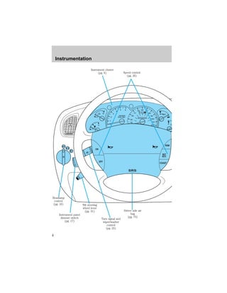
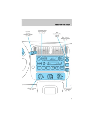
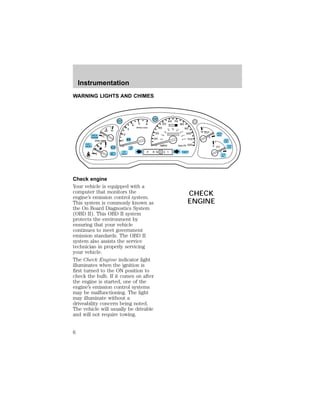
This document is an owner's manual that provides instructions and descriptions for vehicle controls, instruments, features, and systems. It covers topics such as instrument cluster functions, control features, safety systems, starting and driving the vehicle, roadside emergencies, vehicle maintenance, specifications, and safety defect reporting. The manual instructs owners on proper vehicle usage and aims to reduce risks through descriptions of warning lights, safety information, and operating instructions.

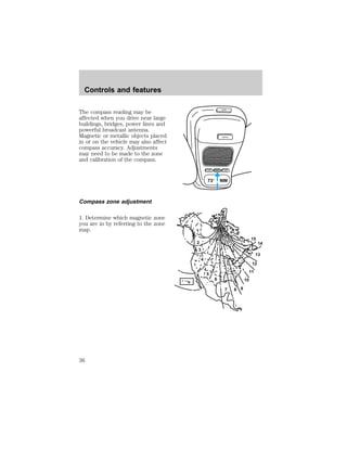
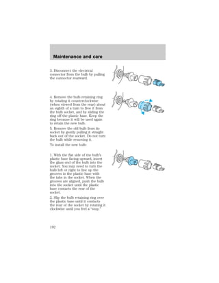
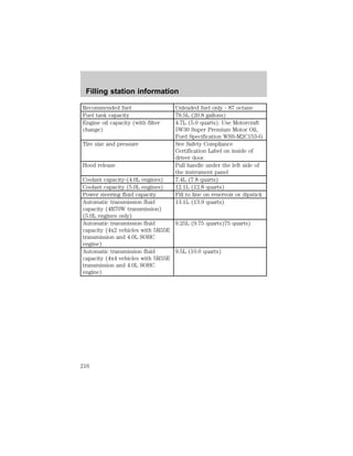
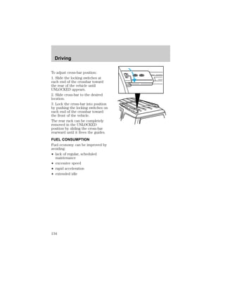
![2. Press and hold the MODE
control until VAR appears in the
display, then release. The display
should show the current zone
number.
3. Press the MODE control until
the desired zone number appears.
The display will flash and then
return to normal operation. The
zone is now updated.
Compass calibration adjustment
Perform this adjustment in an
open area free from steel
structures and high voltage lines:
² Press and hold the MODE
control until CAL appears in the
display (approximately eight
seconds) and release.
² Drive the vehicle slowly (less
than 5 km/h [3 mph]) in circles
until CAL indicator turns off in
about 2–3 complete circles.
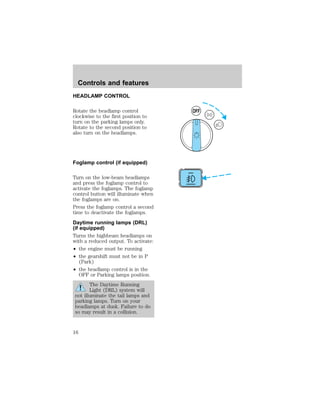
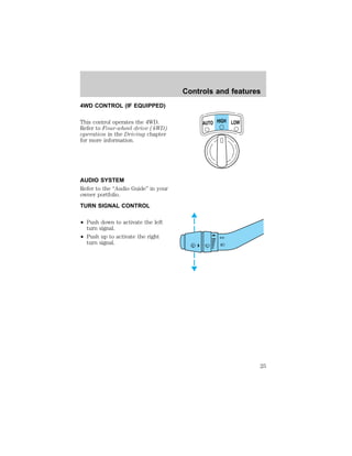
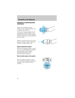
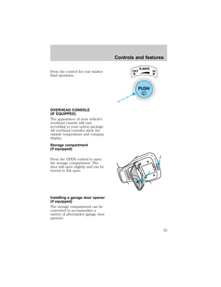
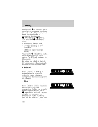
AUTOLAMP DELAY SYSTEM
(IF EQUIPPED)
The autolamp sets the headlamps
to turn on and off automatically.
The autolamp may be set to:
² turn on the lamps automatically
at night
² turn off the lamps automatically
during daylight
² keep the lamps on for up to
three minutes after the key is
turned to OFF
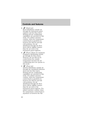
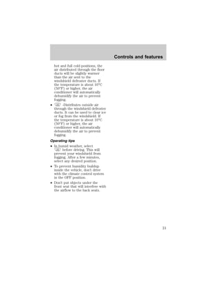
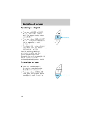
Controls and features
LAMP MODE LAMP
9 VAR
LAMP MODE LAMP
CAL
37](https://image.slidesharecdn.com/98mountaineer-140905151944-phpapp01/85/98-mountaineer-37-320.jpg)
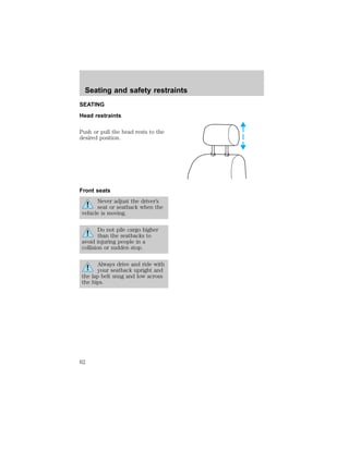
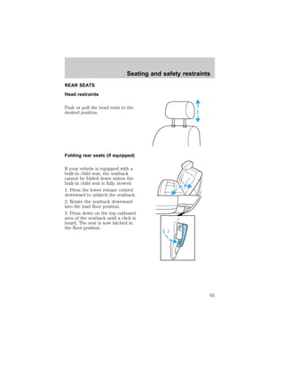
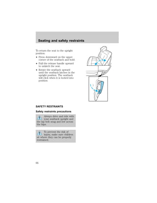
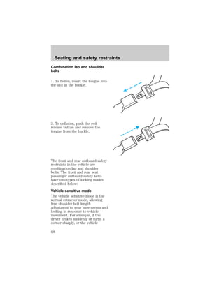
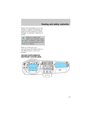
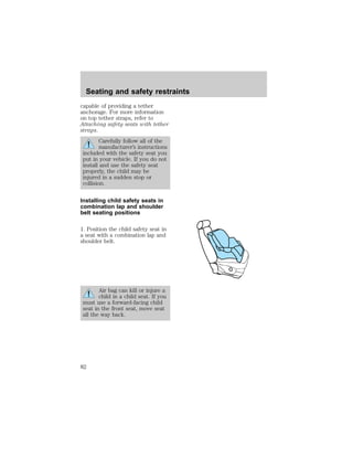
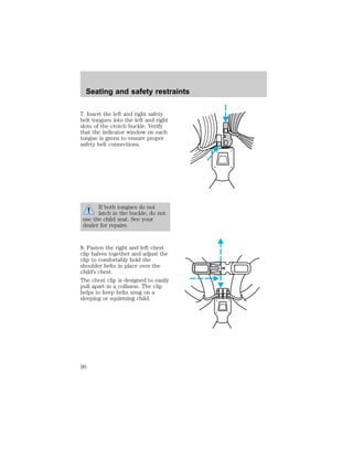
![Seating and safety restraints
younger and who weigh 18 kg
[40 lbs] or less), you must put
them in safety seats made
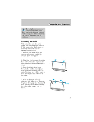
especially for children. Check your
local and state or provincial laws
for specific requirements regarding
the safety of children in your
vehicle.
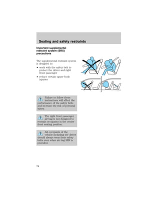
Never let a passenger hold
a child on his or her lap
while the vehicle is moving. The
passenger cannot protect the
child from injury in a collision.
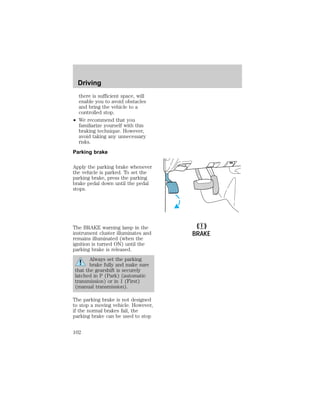
Always follow the instructions and
warnings that come with any infant
or child restraint you might use.
When possible, place children in
the rear seat of your vehicle.
Accident statistics suggest that
children are safer when properly
restrained in the rear seating
positions than in the front seating
position.
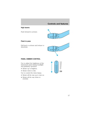
Children and safety belts
Children who are too large for
child safety seats (as specified by
your child safety seat
manufacturer) should always wear
safety belts.
Follow all the important safety
restraint and air bag precautions
that apply to adult passengers in
your vehicle.
If the shoulder belt portion of a
combination lap and shoulder belt
can be positioned so it does not
cross or rest in front of the child’s
79](https://image.slidesharecdn.com/98mountaineer-140905151944-phpapp01/85/98-mountaineer-79-320.jpg)
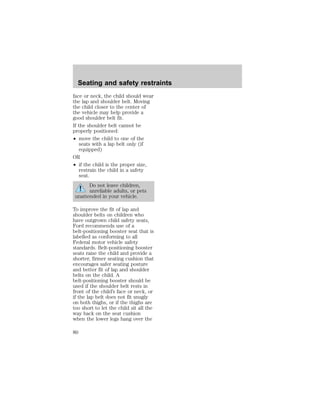
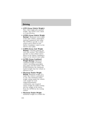
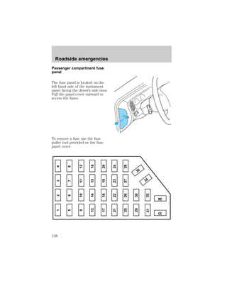
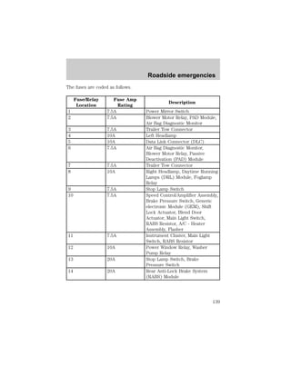
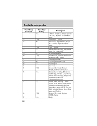
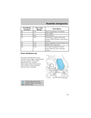
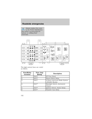
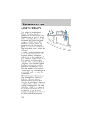
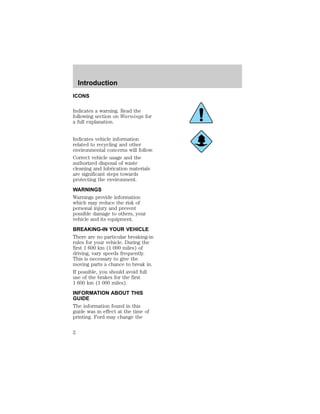
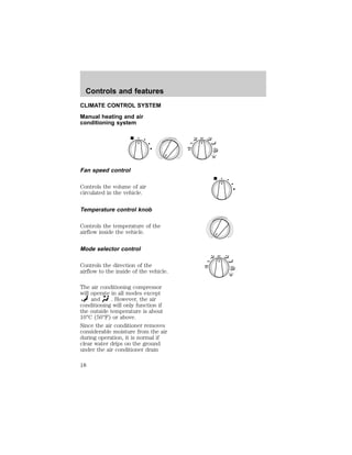
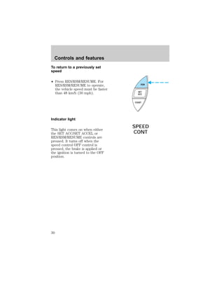
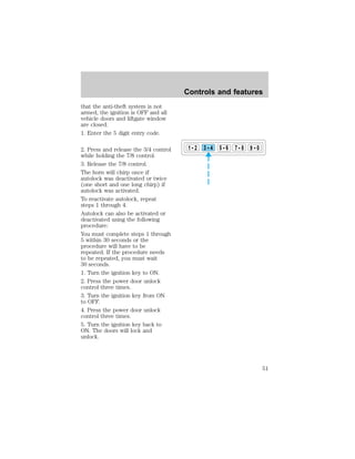
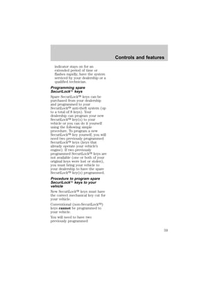
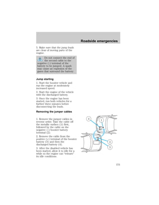
![Roadside emergencies
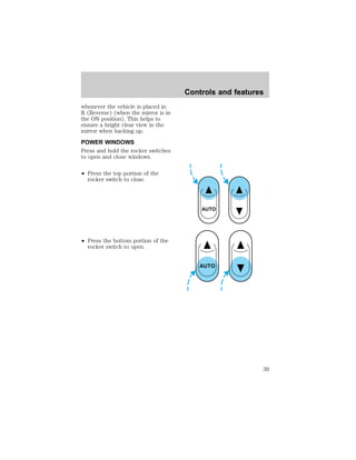
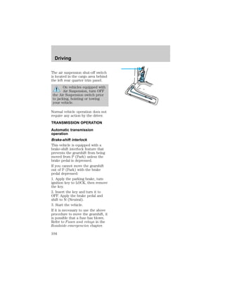
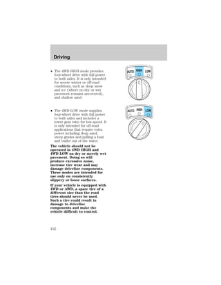
Fuse/Relay
Location
Fuse Amp
Rating
Description
PCM Power
Relay
— PCM Power Relay
Fuel Pump Relay — Fuel Pump Relay
Horn Relay — Horn Relay
Washer Pump
Relay
— Washer Pump Relay
Fog Lamp Relay — Fog Lamp Relay
Starter Relay — Starter Relay
Blower Motor
Relay
— Blower Motor Relay
1 Resistor Fuse [7ca]
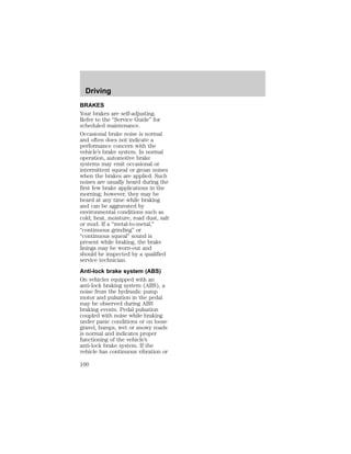
2 Diode Anti-Lock Brakes Indicator
3 Diode Electronic Engine Controls
* Mini Fuses ** Maxi Fuses 1 5.0L Engines Only
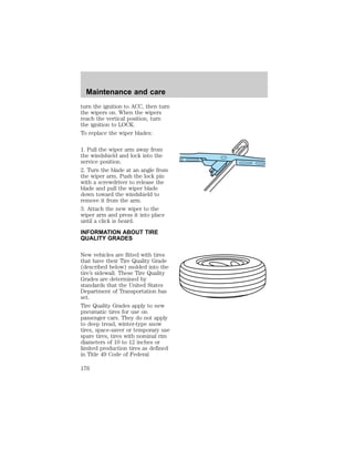
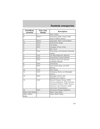
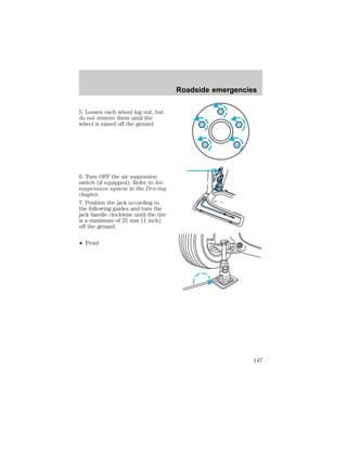
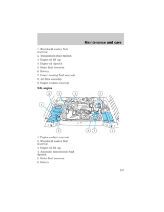
CHANGING THE TIRES
If you get a flat tire while driving,
do not apply the brake heavily.
Instead, gradually decrease your
speed. Hold the steering wheel
firmly and slowly move to a safe
place on the side of the road.
Spare tire information
Your vehicle is equipped with a
spare tire that may be used as a
spare or a regular tire. The spare
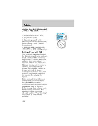
tire is not equipped with wheel
trim. The wheel trim from the
original wheel/tire may be used on
the spare.
If your vehicle is equipped with
4WD or AWD, a spare tire of a
different size than the road
tires should not be used. Such
144](https://image.slidesharecdn.com/98mountaineer-140905151944-phpapp01/85/98-mountaineer-144-320.jpg)
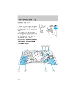
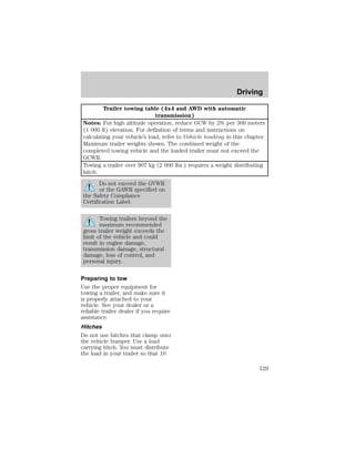
![regulations and standards for
recycling and disposing of
automotive fluids.
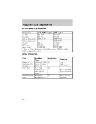
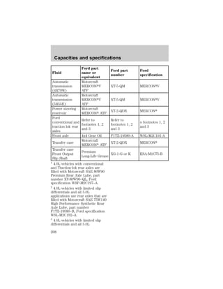
Coolant refill capacity
To find out how much fluid your
vehicle’s cooling system can hold,
refer to Refill capacities in the
Capacities and specifications
chapter.
Have your dealer check the engine
cooling system for leaks if you
have to add more than a liter
(quart) of engine coolant per
month.
Severe winter climate
If you drive in extremely cold
climates (less than –36°C [–34°F]),
it may be necessary to increase the
coolant concentration above 50%.
Refer to the chart on the coolant
container to ensure the coolant
concentration in your vehicle is
such that the coolant will not
freeze at the temperature level in
which you drive during winter
months. Never increase the engine
coolant concentration above 60%.
Leave a 50/50 mixture of engine
coolant and water in your vehicle
year-round in non-extreme
climates.
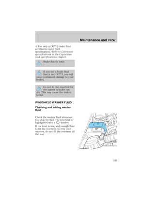
CHECKING AND ADDING
POWER STEERING FLUID
Check the power steering fluid at
least twice a year. If adding fluid is
necessary, use only MERCONt
ATF power steering fluid.
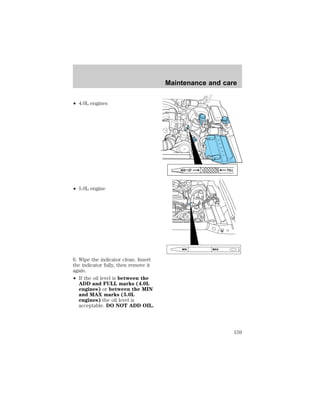
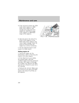
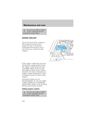
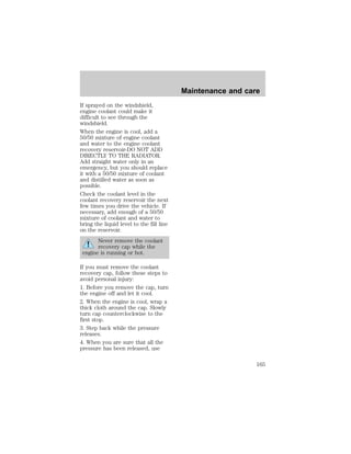
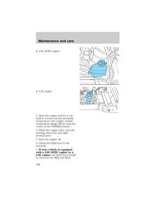
Maintenance and care
167](https://image.slidesharecdn.com/98mountaineer-140905151944-phpapp01/85/98-mountaineer-167-320.jpg)
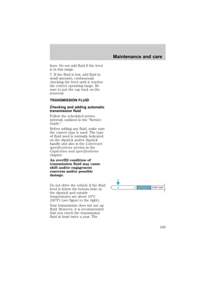
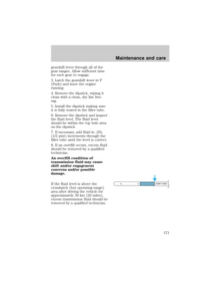
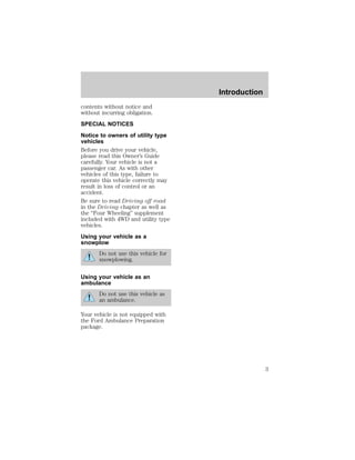
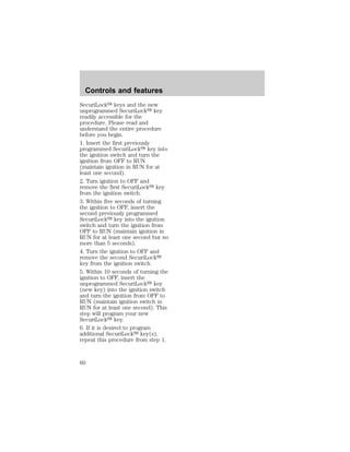
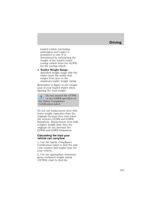
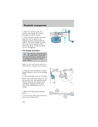
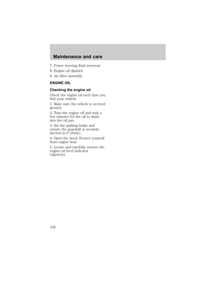
![fluid level should be checked if the
transmission is not working
properly, i.e., if the transmission
slips or shifts slowly or if you
notice some sign of fluid leakage.
Transmission fluid should be
checked at normal operating
temperatures 66°C-77°C
(150°F-170°F) on a level surface.
The normal operating temperature
can be reached after approximately
32 km (20 miles) of driving.
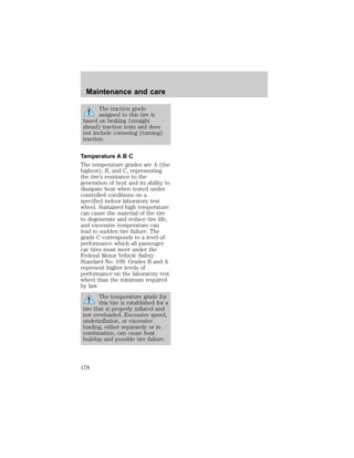
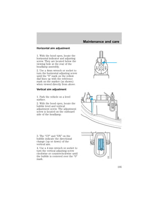
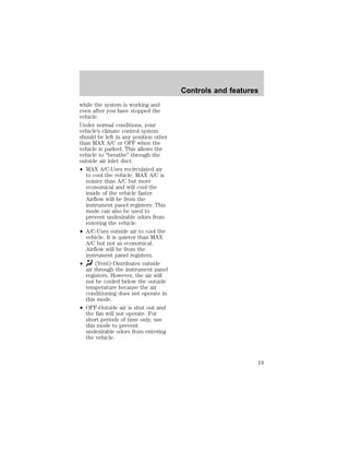
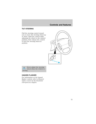
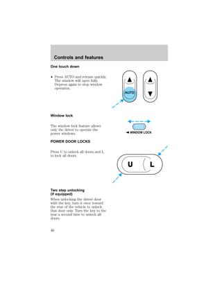
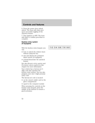
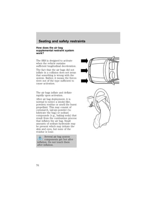
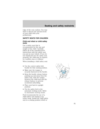
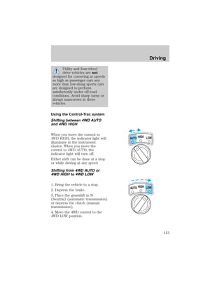
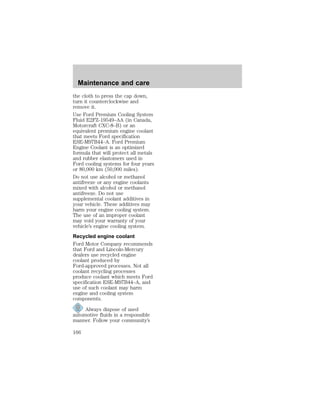
The transmission fluid should be in
this range if at normal operating
temperature (66°C-77°C
[150°F-170°F]) (see figure to the
right).
The transmission fluid should be in
this range if at room temperature
(10°C-35°C [50°F-95°F]) (see
figure to the right).
If your vehicle has been operated
for an extended period at high
speeds, in city traffic during hot
weather or pulling a trailer, the
vehicle should be turned off for
about 30 minutes to allow the fluid
to cool before checking.
1. Park the vehicle on a level
surface and engage the parking
brake.
2. With the parking brake engaged
and your foot on the brake pedal,
start the engine and move the
DON’T ADD
DON’T ADD
Maintenance and care
170](https://image.slidesharecdn.com/98mountaineer-140905151944-phpapp01/85/98-mountaineer-170-320.jpg)