This document provides an overview and instructions for various features of a Ford vehicle. It begins with Ford's commitment to excellence and customer satisfaction. It then describes the instrument panel and cluster, including warning lights and gauges. It provides instructions for finding information in the owner's guide and details various vehicle features and systems.


![231
WARNING
Do not put windshield washer fluid in
the container for the engine coolant.
Use specially formulated windshield washer fluid
rather than plain water, because specially
formulated washer fluids contain additives that
dissolve road grime. For safety reasons, washer
fluids containing an appropriate antifreeze such as
methanol should be used in freezing weather
(temperatures below 32°F [0°C]). State or local
regulations on Volatile Organic Compounds (VOCs)
may restrict use of the most common antifreeze,
methanol. Washer fluids containing non-methanol
antifreeze agents should be used only if they
provide cold weather protection without damaging
the vehicle’s paint finish, wiper blades, and
windshield washer system.
Engine Coolant
Checking the Engine Coolant
NOTE: Be sure to read and understand
Precautions When Servicing Your Vehicle at the
beginning of this chapter.
WARNING
The cooling fan is automatic and may
come on at any time. Always disconnect
the negative terminal of the battery
before working near the fan.](https://image.slidesharecdn.com/97continental-140906074524-phpapp01/75/97continental-232-2048.jpg)

![Do not use alcohol or methanol antifreeze or any
engine coolants mixed with alcohol or methanol
antifreeze. Do not use supplemental coolant
additives in your vehicle. These additives may harm
your engine cooling system. The use of an improper
coolant may void the warranty of your vehicle’s
engine cooling system.
Recycled engine coolant
Ford Motor Company recommends that Ford and
Lincoln-Mercury dealers use recycled engine coolant
produced by Ford-approved processes. Not all
coolant recycling processes produce coolant which
meets Ford specification ESE-M97B44-A, and use of
such coolant may harm engine and cooling system
components.
Always dispose of used automotive fluids in a
responsible manner. Follow your community’s
regulations and standards for recycling and disposing
of automotive fluids.
234
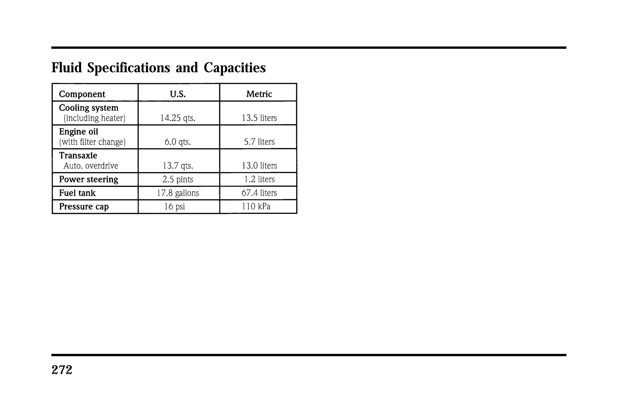
Coolant refill capacity
To find out how much fluid your vehicle’s cooling
system can hold, refer to Refill capacities in the
Capacities and specifications chapter.
Have your dealer check the engine cooling system
for leaks if you have to add more than a quart
(liter) of engine coolant per month.
Severe winter climate
If you drive in extremely cold climates (less than
-34°F [-36°C]), it may be necessary to increase the
coolant concentration above 50%. Refer to the chart
on the coolant container to ensure the coolant
concentration in your vehicle is such that the
coolant will not freeze at the temperature level in
which you drive during winter months. Never
increase the engine coolant concentration above
60%. Leave a 50/50 mixture of engine coolant and
water in your vehicle year-round in non-extreme
climates.](https://image.slidesharecdn.com/97continental-140906074524-phpapp01/75/97continental-235-2048.jpg)


![291
NOTE: The Federal Communications Commission
(FCC) or the Canadian Radio Telecommunications
Commission (CRTC) regulates the use of mobile
communications systems — such as two-way radios,
telephones, and theft alarms — that are equipped
with radio transmitters. Any such equipment
installed in your vehicle should comply with FCC
or CRTC regulations and should be installed only by
a qualified technician.
NOTE: Mobile communications systems may harm
the operation of your vehicle, particularly if they are
not properly designed for automotive use or are not
properly installed. For example, when operated,
such systems may cause the engine to stumble or
stall. In addition, such systems may themselves be
damaged or their operation affected by operating
your vehicle. (Citizens band [CB] transceivers,
garage door openers, and other transmitters whose
power output is 5 watts or less will not ordinarily
affect your vehicle’s operation.)
NOTE: Because we have no control over the
installation, design, or manufacture of such systems,
Ford cannot assume responsibility for any adverse
effects or damage that may result if you use this
equipment.](https://image.slidesharecdn.com/97continental-140906074524-phpapp01/75/97continental-289-2048.jpg)