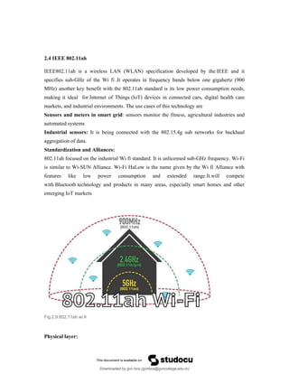
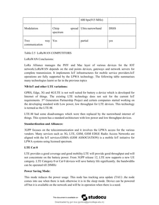
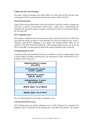
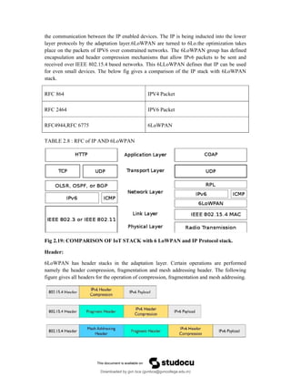
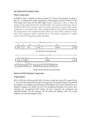
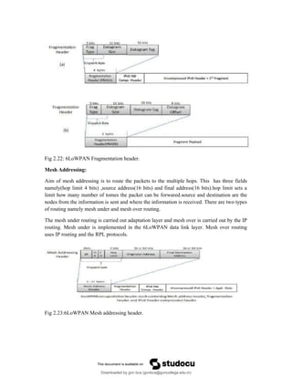
The document provides an overview of IoT protocols and access technologies including physical and MAC layers of various standards like IEEE 802.15.4, 802.15.4g, and 802.15.4e, detailing their functionalities and applications. It discusses wireless access technologies such as Zigbee, LoRa, LTE-M, and others, highlighting their use in smart devices and industrial applications. Additionally, it explores standardization efforts and competitive technologies, emphasizing the importance of reliable communication and security within IoT frameworks.

![Half duplex mode: as half duplex mode is used there is reduction in cost and most sensors
work on this mode.
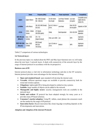
Feature CAT 0 CAT 1
DL Peak rate 10 Mbps 1 Mbps
UE Peak rate 5 Mbps 1 Mbps
DUPLEX MODE YES HALF
Table 2.6 CAT 0 AND CAT 1
LTE –M
3GPP LTE Release 13 has enabled the development of LTE-M (LTE-MTC [Machine
Type Communication]), which includes eMTC (enhanced Machine Type Communication).It
is considered as a low power wide area network (LPWAN) for longer range of Mobile
devices and services. It differs from others by lower receiver bandwidth, lower data rate, half
duplex mode and enhanced discontinuous reception.
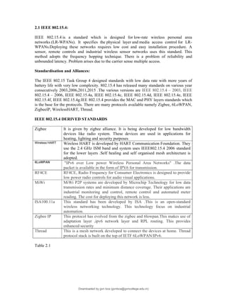
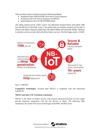
NB-IOT
Narrowband-Internet of Things (NB-IoT) is a standard developed by 3GPP for generating
low power wide area (LPWA) technology and wide range of services for IoT devices. NB-
IoT significantly improves the power consumption of user devices, system capacity and
spectrum efficiency, especially in deep coverage. Battery life has been improved for more
number of usecases.It is cost efficient and provides good indoor coverage.
NB IoT uses the orthogonal frequency division multiple access with features of uplink and
downlink frequency of 200 kHz. Many companies provide so many proposals namely
Narrowband GSM (NOKIA proposal)
Extended coverage GSM(ERICSSON proposal)
Narrowband LTE(Alcatel proposal)
Fig 2.16 :NB-IoT Deployment options
Downloaded by gvn bca (gvnbca@gvncollege.edu.in)
lOMoARcPSD|20972679](https://image.slidesharecdn.com/internet-of-things-2-250121064210-2e05bde3/85/internet-of-things-2-pdf-23-320.jpg)


![Zigbee technology [autosaved]](https://cdn.slidesharecdn.com/ss_thumbnails/zigbeetechnologyautosaved-140716030459-phpapp02-thumbnail.jpg?width=640&height=640&fit=bounds)