1. Chapter-5, Sequential Circuits
Synchronous Sequential Logic
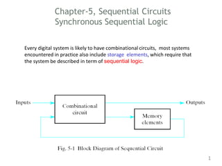
Every digital system is likely to have combinational circuits, most systems
encountered in practice also include storage elements, which require that
the system be described in term of sequential logic.
1
3. INTRODUCTION:
• Flip – flops have two stable states and hence they are
bistable multivibrators. The two stable states are High
(logic 1) and Low (logic 0).
• They can switch between the states under the influence of
a control signal (clock or enable) i.e. they can ‘flip’ to one
state and ‘flop’ back to other state.
• They are binary storage devices because they can store
binary data (0 or 1).
4. INTRODUCTION:
• They are also known as signal change sensitive
devices which mean that the change in the level of
clock signal will bring change in output of the flip
flop.
• A Flip – flop works depending on clock pulses.
• Flip flops are also used to control the digital
circuit’s functionality. They can change the
operation of a digital circuit depending on the state
5. CONVENTIONS
• The two outputs are complementary to each
other.
• If Q is 1 that is set Q’ to 0.
• If Q is 0, reset Q’ to 1. (Q and Q’ can’t be at the
same state simultaneously. If it happens, it will
violate the definition of the flip-flop and hence is
called undefined condition).
6. • Q is called the state of the flip-flop whereas Q’
is called complementary state of the flip-flop.
• When the output Q is either 0 or 1, it remains
in that state unless one or more inputs are
excited to effect the change on the output.
7. FLIP-FLOPS
TYPES of flip-flops
• RS FLIP FLOP
• D FLIP FLOP
• JK FLIP FLOP
• T FLIP FLOP
• pulse-triggered flip-flops: outputs response to
the triggering pulse
• edge-triggered flip-flops: outputs responses to
the control input edge
9. S-R FLIP FLOP
• The S-R flip-flop is basic flip-flop among all the flip-
flops. All the other flip flops are developed after SR-flip-
flop.
• SR flip flop is represented as shown below
10. S-R FLIP FLOP
• Any flip flop can be build using logic gates. NAND and NOR
gates were used as they are universal gates.
11. The Basic SR Flip-flop
The Basic SR Flip-flop with clock
12. JK-FLIP FLOP
• The J-K flip-flop is operationally similar to the S-
R flip-flop.
• The J-K flip-flop is clock driven like the clocked
S-R flip-flop.
• The difference is that the J-K flip-flop will retain
its output status when two lows are present at
its inputs. Also, when both inputs are high, the
outputs will toggle on and off
13. WORKING
• Q and Q' are feedback to the pulse-steering
NAND gates.
• No invalid state.
• Include a toggle (switch) state.
• J=HIGH (and K=LOW) - a SET state
• K=HIGH (and J=LOW) - a RESET state
• both inputs LOW - a no change
• both inputs HIGH - a toggle
14. • Toggling means ‘Changing the next state output to
complement of the present state output’
• Toggling will cause the output to complement
again and again.
• This complement operation continues until the
Clock pulse goes back to 0. Since this condition is
undesirable, we have to find a way to eliminate this
condition.
• This undesirable behavior can be eliminated by
Edge triggering of JK flip-flop or by using master
slave JK Flip-flops.
17. D-FLIP FLOP
The D flip-flop is widely used. It is also known as a
"data" or "delay" flip-flop and negative edge
triggered flip flop.
By comparing R-S, J-K, and D flip-flops one can
see that the D flip-flop never has an unknown
state, unlike the R-S and J-K.
• single input D (data)
• D=HIGH - a SET state
• D=LOW - a RESET state
19. CLK D J K Q Q’
1 1 0 1 0 1
1 1 1 0 1 0
J=Q
D-FLIP FLOP TRUTH TABLE
20. T-FLIP FLOP
• AT flip flop is like JK flip-flop.
• These are basically a single input version of JK
flip flop.
• This modified form of JK flip-flop is obtained by
connecting both inputs J and K together.
•
• This flip-flop has only one input along with the
clock input.
21. clk T J K Q Q’ S R Q Q’
1 0 0 0 1 0 0 0 1 0 previous
values
0 1 0 0 0 1
1 1 1 1 1 0 0 1 0 1 compliment
of previous
values
0 1 1 0 1 0
22. TRIGGERING OF FLIP FLOPS
)> FLIP - FLOPS CHANGE STATE ONLY WHEN A CLOCK SIGNAL
IS PRESENT.
)> CLOCK SIGNAL ISNOT NECESSARILY INSTANTANEOUS SO THERE
NEEDS TO BE A WAY TO PREVENT THE FLIP-FLOP FROM
CHANGING STATE MULTIPLE TIMES DURING A CLOCK CYCLE.
)> 2 WAYS TO ACHIEVE THIS :
)> ONLY CHANGE STATE ONCE THE CLOCK CYCLE IS FINISHED.
THISTYPE OF FLIP-FLOP IS CALLED A MASTER -SLAVE FLIP-FLOP.
)> ONLY TRIGGERS DURING A SIGNAL TRANSITION. THIS TYPE IS
CALLED AN EDGE - TRIGGERED FLIP-FLOP.
23. MASTER - SLAVE FLIP – FLOPS
A pulse-triggered flip-flop consists of two latches, one acts
as a master and the other acts as a slave. Master-slave
flip-flop allows one flip-flop to change state as the clock
pulse is active.
Output from one flip-flop goes into another flip-flop,which is
attached to an inverted clock input. State of the first flip-flop
settles by the time its output changes the state of the second
flip-flop after the clock pulse has finished and stable outPut
is acheved.
24. EDGE TRIGGERED FLIP - FLOPS
5
);>- AN EDGE - TRIGGERED FLIP- FLOP IS A BISTABLE DEVICE
WHOSE STATE DEPENDS ON THE SYNCHRONOUS INPUTS
EITHER AT THE POSITIVE EDGE OR AT THE NEGATIVE
EDGE OF A CLOCK PULSE.
EDGE TRIGGERED FLIP -FLOPS TRIGGER ONLY WHEN THE
PULSE IS IN TRANSITION.
SOME TRIGGER DURING A POSITIVE TRANSITION ( 0 -TO - 1)
CALLED POSITIVE EDGE TRIGGERED FLIP - FLOPS. OTHERS
TRIGGER DURING A NEGATIVE TRANSITION ( 1-TO - 0 )
CALLED NEGATIVE EDGE TRIGGERED FLIP - FLOPS.
25. 5-4 Analysis of Clocked Sequential Circuits
25
The analysis of a sequential circuit consists of
obtaining a table or a diagram for the time sequence of
inputs, outputs, and internal states. It is also possible to
write Boolean expressions that describe the behavior of
the sequential circuit. These expressions must include
the necessary time sequence, either directly or
indirectly.
26. State Equations
26
The behavior of a clocked sequential circuit can be
described algebraically by means of state equations. A state
equation specifies the next state as a function of the
present state and inputs.
27. State Equation
27
A(t+1) = A(t) x(t) + B(t) x(t)
B(t+1) = A`(t) x(t)
A state equation is an algebraic expression that specifies
the condition for a flip-flop state transition. The left side of
the equation with (t+1) denotes the next state of the flip-
flop one clock edge later. The right side of the equation is
Boolean expression that specifies the present state and
input conditions that make the next state equal to 1.
Y(t) = (A(t) + B(t)) x(t)`
28. State Table
The time sequence of inputs, outputs, and flip-flop states
can be enumerated in a state table (sometimes called
transition table).
28
29. State Diagram
The information available in a state table can be
represented graphically in the form of a state diagram. In
this type of diagram, a state is represented by a circle, and
the transitions between states are indicated by directed
lines connecting the circles.
1/0 : means input =1
output=0
29
30. Mealy and Moore Models (1)
•The most general model of a sequential circuit has inputs,
outputs, and internal states. It is customary to distinguish
between two models of sequential circuits:
the Mealy model and the Moore model
• They differ in the way the output is generated.
- In the Mealy model, the output is a function of both the
present state and input.
- In the Moore model, the output is a function of the present
state only.
30
31. Mealy and Moore Models (2)
31
When dealing with the two models, some books and other
technical sources refer to a sequential circuit as a finite state
machine abbreviated FSM.
- The Mealy model of a sequential circuit is referred to as a
Mealy FSM or Mealy machine.
-The Moore model is refereed to as a Moore FSM or Moore
machine.