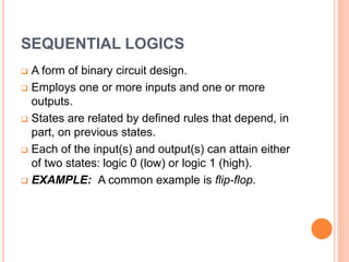
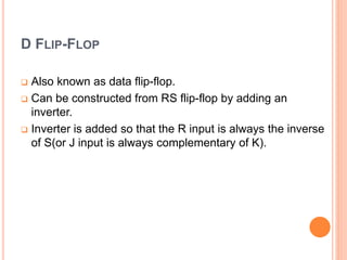
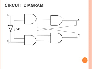
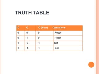
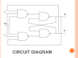
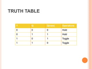
SEQUENTIAL LOGICS
 A form of binary circuit design.
 Employs one or more inputs and one or more
outputs.
 States are related by defined rules that depend, in
part, on previous states.
 Each of the input(s) and output(s) can attain either
of two states: logic 0 (low) or logic 1 (high).
 EXAMPLE: A common example is flip-flop.
FLIP-FLOP
 A device that can store 1 bit of information.
 It is a clocked device, which can change its value
only at positive clock edges.
 When the clock is not at a positive edge, the flip-
flop maintains (holds) its value.
Q
Q’
Inputs
Normal Output
Inverted Output
 They have two stable sates and can be switched from
one to the other by appropriate inputs.
 These stable conditions are usually called the states
of the circuit.
TYPES OF FLIP-FLOPS
There are four types of flip-flops.
 Basic RS flip-flop
 Clocked RS flip-flop
 JK flip-flop
 D flip-flop
 T flip-flop
 Master slave flip-flop
D FLIP-FLOP
 Also known as data flip-flop.
 Can be constructed from RS flip-flop by adding an
inverter.
 Inverter is added so that the R input is always the inverse
of S(or J input is always complementary of K).
CIRCUIT DIAGRAM
D
Cp
D’
Q
Q’
D Q Q (New) Operations
0 0 0 Reset
0 1 0 Reset
1 0 1 Set
1 1 1 Set
TRUTH TABLE
T FLIP-FLOP
 Also known as toggle flip-flop.
 It has only the toggle and hold operation.
 If toggle mode operation. The output will toggle from 1 to
0 or vice versa.
T
Q
Cp
Q’
T
CIRCUIT DIAGRAM
T Q Q(new) Operations
0 0 0 Hold
0 1 1 Hold
1 0 1 Toggle
1 1 0 Toggle
TRUTH TABLE

Sequential logics

  • 1.
    SEQUENTIAL LOGICS  Aform of binary circuit design.  Employs one or more inputs and one or more outputs.  States are related by defined rules that depend, in part, on previous states.  Each of the input(s) and output(s) can attain either of two states: logic 0 (low) or logic 1 (high).  EXAMPLE: A common example is flip-flop.
  • 2.
    FLIP-FLOP  A devicethat can store 1 bit of information.  It is a clocked device, which can change its value only at positive clock edges.  When the clock is not at a positive edge, the flip- flop maintains (holds) its value.
  • 3.
    Q Q’ Inputs Normal Output Inverted Output They have two stable sates and can be switched from one to the other by appropriate inputs.  These stable conditions are usually called the states of the circuit.
  • 4.
    TYPES OF FLIP-FLOPS Thereare four types of flip-flops.  Basic RS flip-flop  Clocked RS flip-flop  JK flip-flop  D flip-flop  T flip-flop  Master slave flip-flop
  • 5.
    D FLIP-FLOP  Alsoknown as data flip-flop.  Can be constructed from RS flip-flop by adding an inverter.  Inverter is added so that the R input is always the inverse of S(or J input is always complementary of K).
  • 6.
  • 7.
    D Q Q(New) Operations 0 0 0 Reset 0 1 0 Reset 1 0 1 Set 1 1 1 Set TRUTH TABLE
  • 8.
    T FLIP-FLOP  Alsoknown as toggle flip-flop.  It has only the toggle and hold operation.  If toggle mode operation. The output will toggle from 1 to 0 or vice versa.
  • 9.
  • 10.
    T Q Q(new)Operations 0 0 0 Hold 0 1 1 Hold 1 0 1 Toggle 1 1 0 Toggle TRUTH TABLE