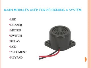
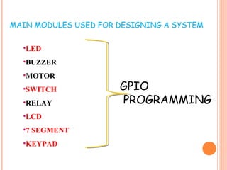
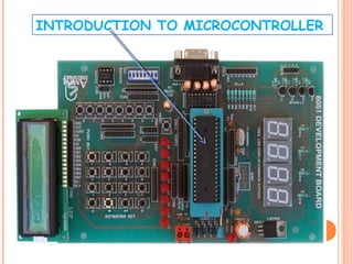
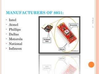
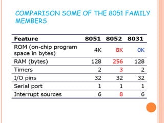
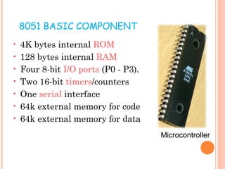
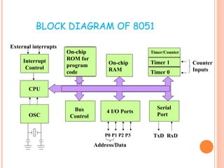
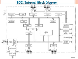
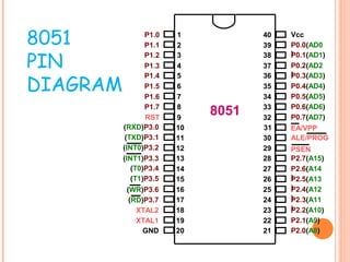
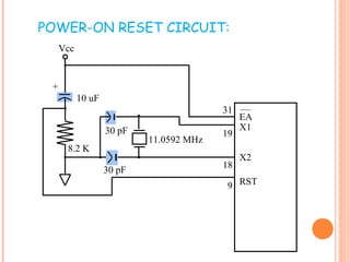
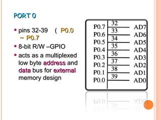
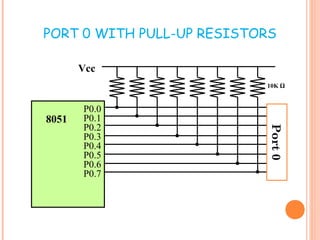
8051 Microcontroller
introduction
and
its Applications
•PCB
•Battery 
•Mica
•Speaker .
•Ringer
•Vibrator 
•Keypad 
•Antenna 
•Display
•Touch
•Battery Connector.
•SIM Connector
•Charging Connector 
•Earphone Connector
Which
device
?
•PCB
•Battery 
•Mica
•Speaker .
•Ringer
•Vibrator 
•Keypad 
•Antenna 
•Display
•Touch
•Battery Connector.
•SIM Connector
•Charging Connector 
•Earphone Connector
EXAMPLES OF EMBEDDED SYSTEMS
• Keyboard
• Printer
• video game player
• MP3 music players
• Mobile phone units
• Domestic (home) appliances
• Automotive controls
•LED
•BUZZER
•MOTOR
•SWITCH
•RELAY
•LCD
•7 SEGMENT
•KEYPAD
MAIN MODULES USED FOR DESIGNING A SYSTEM
•LED
•BUZZER
•MOTOR
•SWITCH
•RELAY
•LCD
•7 SEGMENT
•KEYPAD
MAIN MODULES USED FOR DESIGNING A SYSTEM
GPIO
PROGRAMMING
Microprocessor
Microcontroller
RISC:
Reduced Instruction Set Computer. is a type of
microprocessor architecture that utilizes a small, highly-
optimized set of instructions, rather than a more specialized
set of instructions often found in other types of architectures.
CISC:
Complex instruction set computing is a processor design where
single instructions can execute several low-level operations (such
as a load from memory, an arithmetic operation, and a memory
store) or are capable of multi-step operations or addressing
modes within single instructions.
CISC & RISC
CISC RISC
Emphasis on hardware Emphasis on software
Includes multi-clock
complex instructions
Single-clock,
reduced instruction only
Memory-to-memory:
"LOAD" and "STORE"
incorporated in instructions
Register to register:
"LOAD" and "STORE"
are independent instructions
Small code sizes,
high cycles per second
Low cycles per second,
large code sizes
Transistors used for storing
complex instructions
Spends more transistors
on memory registers
CISC versus RISC
INTRODUCTION TO MICROCONTROLLER
ADVANTAGES OF
MICROCONTROLLER
• All peripherals are integrated into a single
chip
• Small size
• Reliable
• Microcontroller may have on chip
ROM,RAM and I/O ports addition ROM,
RAM I/O ports may be interfaced externally
if required
• On chip ROM provide a software security
MANUFACTURERS OF 8051:
• Intel
• Atmel
• Phillips
• Dallas
• Motorola
• National
• Infineon
07/02/1613
CRITERIA IN CHOOSING A MICROCONTROLLER
• Speed
• The amount of ROM and RAM
• The number of I/O ports and Timers
• Size
• Packaging
• Power consumption
• Cost
• Availability of software development tools
• Wide availability and reliable sources of the
microcontrollers
COMPARISON SOME OF THE 8051 FAMILY
MEMBERS
8051 BASIC COMPONENT
• 4K bytes internal ROM
• 128 bytes internal RAM
• Four 8-bit I/O ports (P0 - P3).
• Two 16-bit timers/counters
• One serial interface
• 64k external memory for code
• 64k external memory for data
Microcontroller
BLOCK DIAGRAM OF 8051
CPU
On-chip
RAM
On-chip
ROM for
program
code
4 I/O Ports
Timer 0
Serial
PortOSC
Interrupt
Control
External interrupts
Timer 1
Timer/Counter
Bus
Control
TxD RxDP0 P1 P2 P3
Address/Data
Counter
Inputs
8051 Internal Block Diagram8051 Internal Block Diagram
8051
PIN
DIAGRAM
1
2
3
4
5
6
7
8
9
10
11
12
13
14
15
16
17
18
19
20
40
39
38
37
36
35
34
33
32
31
30
29
28
27
26
25
24
23
22
21
P1.0
P1.1
P1.2
P1.3
P1.4
P1.5
P1.6
P1.7
RST
(RXD)P3.0
(TXD)P3.1
(T0)P3.4
(T1)P3.5
XTAL2
XTAL1
GND
(INT0)P3.2
(INT1)P3.3
(RD)P3.7
(WR)P3.6
Vcc
P0.0(AD0
)P0.1(AD1)
P0.2(AD2
)P0.3(AD3)
P0.4(AD4)
P0.5(AD5)
P0.6(AD6)
P0.7(AD7)
EA/VPP
ALE/PROG
PSEN
P2.7(A15)
P2.6(A14
)P2.5(A13
)P2.4(A12
)P2.3(A11
)P2.2(A10)
P2.1(A9)
P2.0(A8)
8051
POWER-ON RESET CIRCUIT:
30 pF
30 pF
8.2 K
10 uF
+
Vcc
11.0592 MHz
EA
X1
X2
RST
31
19
18
9
PORT 0PORT 0
• pins 32-39pins 32-39 (( P0.0P0.0
~~ P0.7P0.7
• 8-bit R/W –GPIO8-bit R/W –GPIO
• acts as a multiplexedacts as a multiplexed
low bytelow byte addressaddress andand
datadata bus forbus for externalexternal
memory designmemory design
PORT 0 WITH PULL-UP RESISTORS
P0.0
P0.1
P0.2
P0.3
P0.4
P0.5
P0.6
P0.7
8051
Vcc
10K Ω
Port0
PORT 1PORT 1
• pins (1-8pins (1-8 )()( P1.0P1.0 ~~
P1.7P1.7
• 8-bit R/W - GPIO8-bit R/W - GPIO
PORT 2PORT 2
• pins (21-28)pins (21-28) (( P2.0P2.0 ~~
P2.7P2.7 ))
• 8-bit R/W – GPIO8-bit R/W – GPIO
• HighHigh byte of thebyte of the addressaddress
bus for external memorybus for external memory
designdesign
PORT 3PORT 3
• pins (10-17 )pins (10-17 ) (( P3.0P3.0 ~~
P3.7P3.7 ))
• General Purpose I/OGeneral Purpose I/O
• if not using any of theif not using any of the
internal peripheralsinternal peripherals
(timers) or external(timers) or external
interrupts.interrupts.
PORT 3 ALTERNATE FUNCTIONS

8051 microcontroller introduction