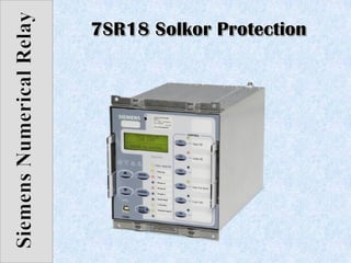
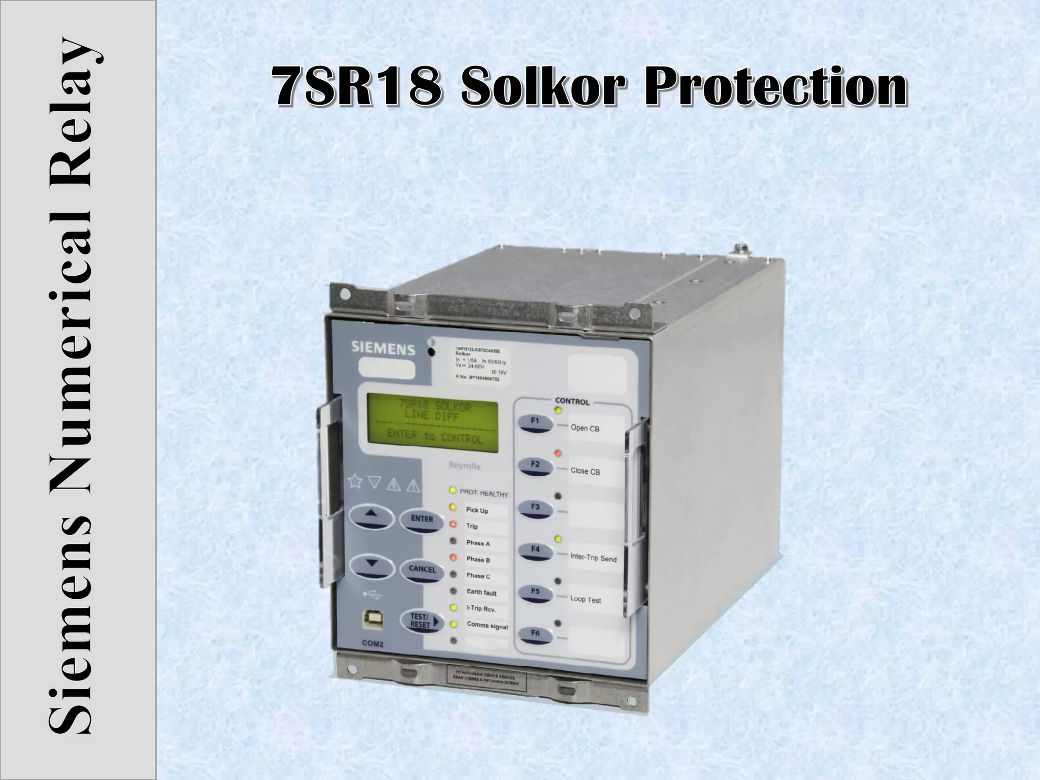
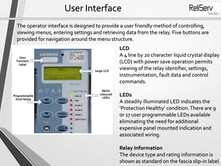
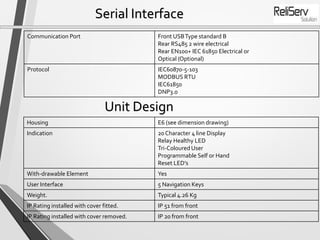
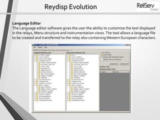
Description
The Solkor, two-ended, line differential relay has been developed to enhance the
Reyrolle family of products. Designed using state-of-the-art hardware technology, it
provides differential protection and control for overhead lines and cable feeders. Housed
in a 4U high, size E6 case, it provides protection, monitoring, instrumentation and
metering with integrated input and output logic, data logging & fault reports.
Communication access to the relay functionality is via a front USB port for local PC
connection or rear RS485 communications port for remote connection.
Monitoring Functions
• Local end and remote end ammeters,
• Differential starters,
• Protection signalling link status,
• General alarms,
• Binary Input / Output status,
• Trip circuit supervision
• Time and date
• Starters
• Fault records
• Event records
• Circuit breaker trip counters
Data Acquisition -Via Communication Interface
Sequence of event records
Up to 1000 events are stored and time tagged to 1 ms resolution.
Fault Records
The last 10 fault records are displayed on the relay fascia and are also available through
the communication interface, with time and date of trip, measured quantities and type of
fault
Waveform recorder
The waveform recorder stores analogue data for all poles and the states of protection
functions, binary inputs, LEDs and binary outputs with user settable pre & post trigger
data
Demand Metering
A record of demand is available.The demand minimum, maximum and average values
for currents, voltages, power and frequency, over a user selectable period of time, is
displayed and can be downloaded.
RealTime Clock
The time and date can be set and are maintained while the relay is de-energised by a
back up storage capacitor.
Function Overview
• 87LThree-phase differential (two elements)
• 85 Inter-trip Feature
• 50 InstantaneousOvercurrent
• 50G/50N Instantaneous Earth Fault
• 51Time Delayed Overcurrent
• 51G/51NTime Delayed Measured/Derived/Earth Fault
• 60CTS-ICT Supervision
Two, three-pole differential elements, each with two stage bias characteristics, are
provided for differential protection. Inter-tripping comes from internal or six independent
external initiation channels. Overcurrent protection can operate as a stand-alone feature, it
can also be configured to operate as ‘guard’ feature and/or back-up in case of protection
signalling communications failure. Connection to CTs is via selectable 1 A or 5 A inputs.
Ratio correction for miss-matched line current transformer ratios is available.The ability to
invert CT inputs is provided to facilitate commissioning.
Communications
• The relay offers a front USB serial port as standard.All of the relays
functions can be set on a PC using Reydisp Evolution via the USB port.
• The connection is made via a USB cable and operates with a ‘plug and
play’ connection. In addition a rear RS485 electrical connection is
available as standard on all units for system interface connections.
• An internal terminating resistor is provided, which can be connected into
the circuit by adding a wire loop between the relevant terminals.
• Both ports can be switched to OFF or set to use either the DNP3.0,
MODBUS-RTU, IEC60870- 5-103 andASCII protocols. IEC61850 is
provided as an ordering option for either Electrical or Optical
connectivity.
Description of Functionality
Current Differential Protection
The relay compares magnitude of measured currents at either end of the protected
feeder, it operates for faults detected within the protected zone.
Backup Overcurrent Protection
In addition to the differential protection, comprehensive overcurrent protection for
phase and earth faults provides back-up IDMTL and DTL characteristics in the event of
a communications link failure.
Guard Relays
If it is necessary to add security to the differential scheme
it is possible to configure an overcurrent element as a
‘guard’ feature.
Inter-tripping
Auxiliary signalling channels are provided for intertripping.
Circuit Breaker Maintenance
A circuit-breaker operations counter is provided.
Construction
• The relay is housed in a 4U high size
E6 case with a removable clear
plastic fascia cover.Two handles are
provided to facilitate the
withdrawal of the relay element
from its case.
• Internal contacts within the case
ensure the CT circuits and normally
closed contacts remain shortcircuit
when the relay is withdrawn.
• The rear connection blocks are
comprised of screw terminals
facilitating M4 ring-crimp
connections, providing a secure and
reliable termination.
User Interface
The operator interface is designed to provide a user friendly method of controlling,
viewing menus, entering settings and retrieving data from the relay. Five buttons are
provided for navigation around the menu structure.
LCD
A 4 line by 20 character liquid crystal display
(LCD) with power save operation permits
viewing of the relay identifier, settings,
instrumentation, fault data and control
commands.
LEDs
A steadily illuminated LED indicates the
‘Protection Healthy’ condition.There are 9
or 17 user programmable LEDs available
eliminating the need for additional
expensive panel mounted indication and
associated wiring.
Relay Information
The device type and rating information is
shown as standard on the fascia slip-in label.
Case Dimensions
Serial Interface
Communication Port Front USBType standard B
Rear RS485 2 wire electrical
Rear EN100+ IEC 61850 Electrical or
Optical (Optional)
Protocol IEC60870-5-103
MODBUS RTU
IEC61850
DNP3.0
Unit Design
Housing E6 (see dimension drawing)
Indication 20 Character 4 line Display
Relay Healthy LED
Tri-Coloured User
Programmable Self or Hand
Reset LED’s
With-drawable Element Yes
User Interface 5 Navigation Keys
Weight. Typical 4.26 Kg
IP Rating installed with cover fitted. IP 51 from front
IP Rating installed with cover removed. IP 20 from front
Reydisp Evolution
Reydisp Evolution is aWindows based software tool, providing the means for the user to
apply settings, interrogate settings and retrieve events and disturbance waveforms from
the device and is common to the entire range of Reyrolle protection relays.
Reydisp Evolution
Language Editor
The Language editor software gives the user the ability to customize the text displayed
in the relays, Menu structure and instrumentation views.The tool allows a language file
to be created and transferred to the relay also containing Western European characters.
Mob No:
Mr. Piyush Rathi- +91-9819614841
Website:
www.reliservsolution.com
Email-ID:
piyush@reliserv.in
sales1@reliserv.in
Address:
Office No: 9, Space Heights,
Plot No. 53/54 , Sector 34,
Kamothe,Navi Mumbai- 410209
Contact us

7SR18 Solkor Protection Relay

  • 2.
    Description The Solkor, two-ended,line differential relay has been developed to enhance the Reyrolle family of products. Designed using state-of-the-art hardware technology, it provides differential protection and control for overhead lines and cable feeders. Housed in a 4U high, size E6 case, it provides protection, monitoring, instrumentation and metering with integrated input and output logic, data logging & fault reports. Communication access to the relay functionality is via a front USB port for local PC connection or rear RS485 communications port for remote connection. Monitoring Functions • Local end and remote end ammeters, • Differential starters, • Protection signalling link status, • General alarms, • Binary Input / Output status, • Trip circuit supervision • Time and date • Starters • Fault records • Event records • Circuit breaker trip counters
  • 3.
    Data Acquisition -ViaCommunication Interface Sequence of event records Up to 1000 events are stored and time tagged to 1 ms resolution. Fault Records The last 10 fault records are displayed on the relay fascia and are also available through the communication interface, with time and date of trip, measured quantities and type of fault Waveform recorder The waveform recorder stores analogue data for all poles and the states of protection functions, binary inputs, LEDs and binary outputs with user settable pre & post trigger data Demand Metering A record of demand is available.The demand minimum, maximum and average values for currents, voltages, power and frequency, over a user selectable period of time, is displayed and can be downloaded. RealTime Clock The time and date can be set and are maintained while the relay is de-energised by a back up storage capacitor.
  • 4.
    Function Overview • 87LThree-phasedifferential (two elements) • 85 Inter-trip Feature • 50 InstantaneousOvercurrent • 50G/50N Instantaneous Earth Fault • 51Time Delayed Overcurrent • 51G/51NTime Delayed Measured/Derived/Earth Fault • 60CTS-ICT Supervision Two, three-pole differential elements, each with two stage bias characteristics, are provided for differential protection. Inter-tripping comes from internal or six independent external initiation channels. Overcurrent protection can operate as a stand-alone feature, it can also be configured to operate as ‘guard’ feature and/or back-up in case of protection signalling communications failure. Connection to CTs is via selectable 1 A or 5 A inputs. Ratio correction for miss-matched line current transformer ratios is available.The ability to invert CT inputs is provided to facilitate commissioning.
  • 5.
    Communications • The relayoffers a front USB serial port as standard.All of the relays functions can be set on a PC using Reydisp Evolution via the USB port. • The connection is made via a USB cable and operates with a ‘plug and play’ connection. In addition a rear RS485 electrical connection is available as standard on all units for system interface connections. • An internal terminating resistor is provided, which can be connected into the circuit by adding a wire loop between the relevant terminals. • Both ports can be switched to OFF or set to use either the DNP3.0, MODBUS-RTU, IEC60870- 5-103 andASCII protocols. IEC61850 is provided as an ordering option for either Electrical or Optical connectivity.
  • 6.
    Description of Functionality CurrentDifferential Protection The relay compares magnitude of measured currents at either end of the protected feeder, it operates for faults detected within the protected zone. Backup Overcurrent Protection In addition to the differential protection, comprehensive overcurrent protection for phase and earth faults provides back-up IDMTL and DTL characteristics in the event of a communications link failure. Guard Relays If it is necessary to add security to the differential scheme it is possible to configure an overcurrent element as a ‘guard’ feature. Inter-tripping Auxiliary signalling channels are provided for intertripping. Circuit Breaker Maintenance A circuit-breaker operations counter is provided.
  • 7.
    Construction • The relayis housed in a 4U high size E6 case with a removable clear plastic fascia cover.Two handles are provided to facilitate the withdrawal of the relay element from its case. • Internal contacts within the case ensure the CT circuits and normally closed contacts remain shortcircuit when the relay is withdrawn. • The rear connection blocks are comprised of screw terminals facilitating M4 ring-crimp connections, providing a secure and reliable termination.
  • 8.
    User Interface The operatorinterface is designed to provide a user friendly method of controlling, viewing menus, entering settings and retrieving data from the relay. Five buttons are provided for navigation around the menu structure. LCD A 4 line by 20 character liquid crystal display (LCD) with power save operation permits viewing of the relay identifier, settings, instrumentation, fault data and control commands. LEDs A steadily illuminated LED indicates the ‘Protection Healthy’ condition.There are 9 or 17 user programmable LEDs available eliminating the need for additional expensive panel mounted indication and associated wiring. Relay Information The device type and rating information is shown as standard on the fascia slip-in label.
  • 9.
  • 10.
    Serial Interface Communication PortFront USBType standard B Rear RS485 2 wire electrical Rear EN100+ IEC 61850 Electrical or Optical (Optional) Protocol IEC60870-5-103 MODBUS RTU IEC61850 DNP3.0 Unit Design Housing E6 (see dimension drawing) Indication 20 Character 4 line Display Relay Healthy LED Tri-Coloured User Programmable Self or Hand Reset LED’s With-drawable Element Yes User Interface 5 Navigation Keys Weight. Typical 4.26 Kg IP Rating installed with cover fitted. IP 51 from front IP Rating installed with cover removed. IP 20 from front
  • 11.
    Reydisp Evolution Reydisp Evolutionis aWindows based software tool, providing the means for the user to apply settings, interrogate settings and retrieve events and disturbance waveforms from the device and is common to the entire range of Reyrolle protection relays.
  • 12.
    Reydisp Evolution Language Editor TheLanguage editor software gives the user the ability to customize the text displayed in the relays, Menu structure and instrumentation views.The tool allows a language file to be created and transferred to the relay also containing Western European characters.
  • 13.
    Mob No: Mr. PiyushRathi- +91-9819614841 Website: www.reliservsolution.com Email-ID: piyush@reliserv.in sales1@reliserv.in Address: Office No: 9, Space Heights, Plot No. 53/54 , Sector 34, Kamothe,Navi Mumbai- 410209 Contact us