Download to read offline


![Site Preparation
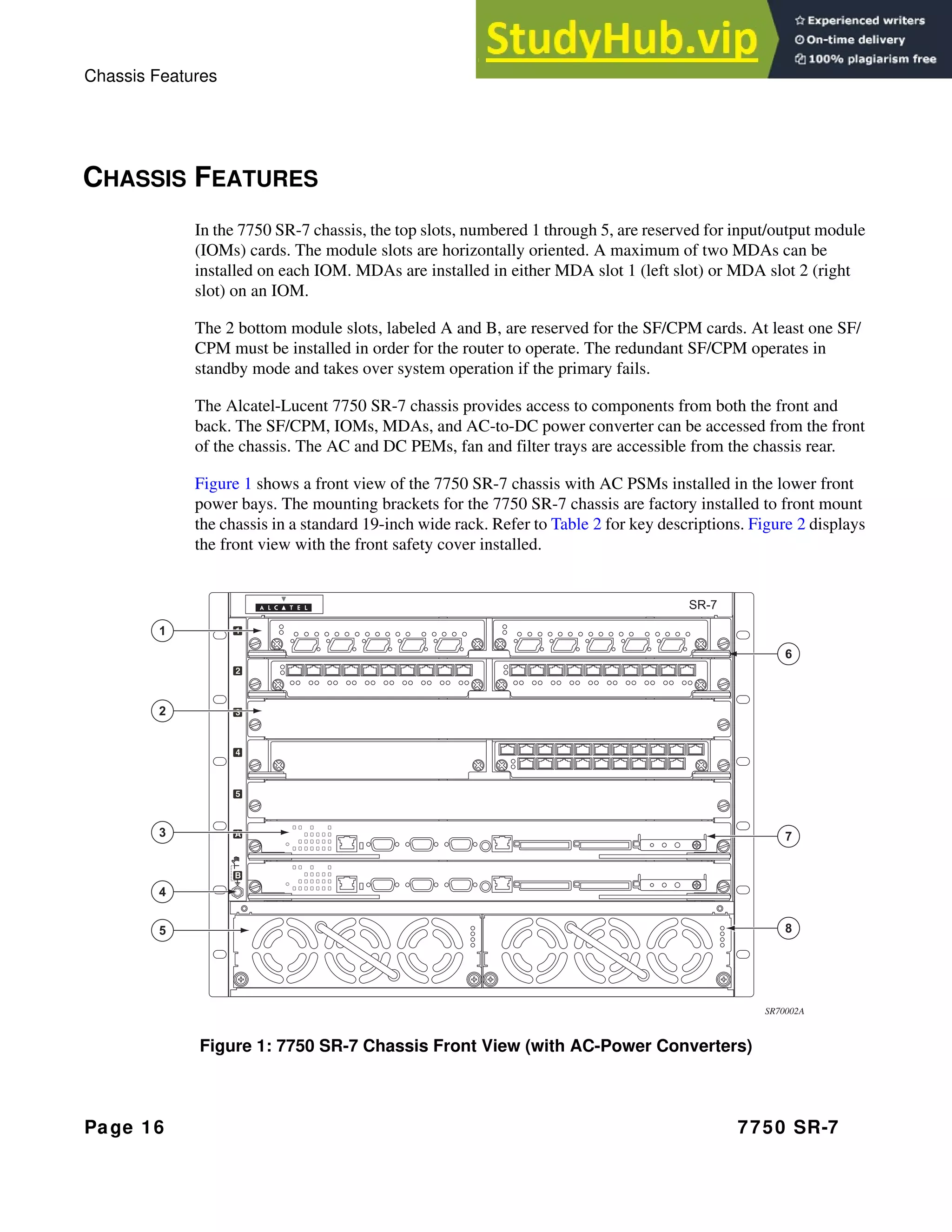
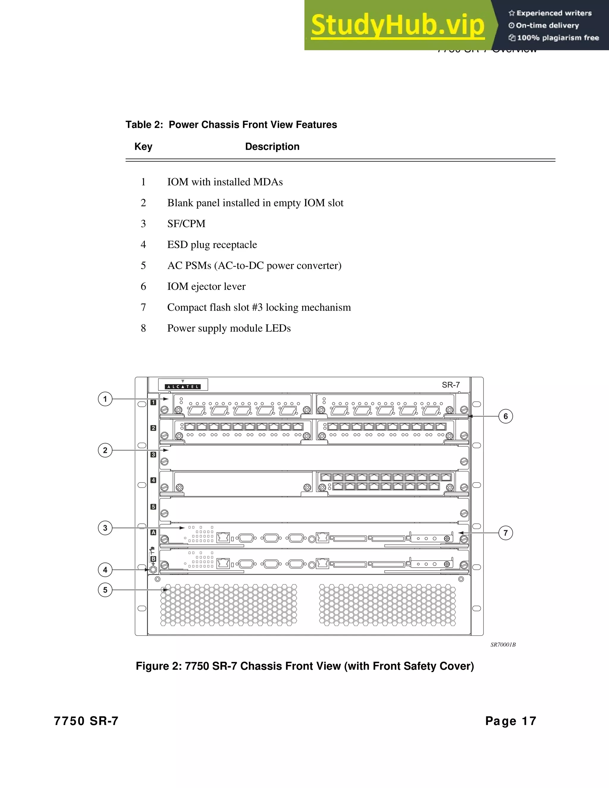
7750 SR-7 Page 47
Cabling
Power
Warning:
• To comply with the GR-1089-CORE, Issue 03, requirement R4-9 [31] standard for
electromagnetic compatibility and safety, all intra-building ports are specified for use with
shielded and grounded cables at both ends.
• The intra-building port(s) of the equipment or sub-assembly is suitable for connection to intra-
building or unexposed wiring or cabling only. The intra-building port(s) of the equipment or sub-
assembly must not be metallically connected to interfaces that connect to the Outside Plant
(OSP) or its wiring. These interfaces are designed for use as intra-building interfaces only (Type
2 or Type 4 ports as described in GR-1089-CORE, Issue 4) and require isolation from the
exposed OSP cabling. The addition of primary protectors is not sufficient protection in order to
connect these interfaces metallically to OSP wiring.
• Bare conductors must be coated with an appropriate antioxidant compound before crimp
connections are made. All unplated connectors, braided strap, and bus bars must be brought to a
bright finish and then coated with an antioxidant before they are connected.
• The equipment under test (EUT) is specified for DC-I power configurations. The battery returns
must remain isolated until they reach the main power buss.
Warning:
• Only service electrical personnel should perform wiring and cabling to the system.
• All power to the equipment rack or cabinet should be disconnect before the installation.
• The power cable(s) must meet your local electric code requirements.
• The PEM circuit breaker is not intended to be used as the chassis ON/OFF switch. Unplug the
power cord from the power source and disconnect the cord from the receptacle on the power
module to remove power.](https://image.slidesharecdn.com/7750sr-7installationguide-230806121649-f8430e3b/75/7750-SR-7-INSTALLATION-GUIDE-47-2048.jpg)


![Establishing Router Connections
Page 92 7750 SR-7
TELNET CONNECTION
Access the router after a successful initialization with a Telnet connection from a PC or
workstation connected to the network after the management port (Figure 31) has been configured
using the bof>address command (see below). Telnet access provides the same options for user
and administrator access as those available through the console port.
To configure the 7750 SR-7 for Telnet access, you need to have a device with Telnet software
located on the same network. The 7750 SR-7 must have a management IP address. The IP address
is manually configured. Each 7750 SR router is limited to a total of 7 inbound/outbound Telnet or
SSH sessions to guarantee that either inbound or outbound sessions will be available. For
information about configuring router parameters, refer to the IP Router Configuration Overview
chapter. For pinout information, refer to Appendix C: Pinout Assignments on page 153.
MAC addresses are listed on a small label on the chassis, IOM, and MDA. The MAC address also
displays in the show router arp command output.
Figure 31: Management Port Connection
CLI Syntax: bof
address ip-address/mask [active|standby]
The 7750 SR-7 must have a management IP address. The IP address is manually configured.
SR40028
Mgmt Port](https://image.slidesharecdn.com/7750sr-7installationguide-230806121649-f8430e3b/75/7750-SR-7-INSTALLATION-GUIDE-92-2048.jpg)


This document provides installation instructions for the 7750 SR-7 system. It includes specifications for the chassis and components, safety guidelines, and step-by-step instructions for setting up the system. The document outlines how to unpack, rack mount, ground, and provide power to the chassis. It also provides details on installing modules, fans, and other components within the chassis.


