This document is a service manual for a CSD 100/125 screw compressor. It provides technical specifications for the compressor, including weight, temperature and pressure parameters, motor details, cooling oil information, electrical connections, and optional features like water cooling and heat recovery. It also covers safety information, describing proper and improper usage, responsibilities of qualified users, dangers associated with electricity, compressed air, springs and other components. The design and function section provides an overview of the compressor components and cabinet, optional accessories, operating states and control modes. Installation guidelines require consideration of ambient conditions.


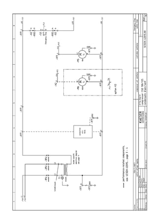
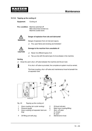
![Directory of Illustrations
Chapter --- page
v
Fig. 1 Three---phase star (wye); four wire; earthed neutral 2 --- 7. . . . . . . . . . . . . . . . . . . . . . .
Fig. 2 Three---phase star (wye); three wire; earthed neutral 2 --- 7. . . . . . . . . . . . . . . . . . . . . .
Fig. 3 Location of safety signs 3 --- 19. . . . . . . . . . . . . . . . . . . . . . . . . . . . . . . . . . . . . . . . . . . . . .
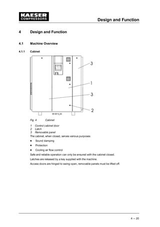
Fig. 4 Cabinet 4 --- 20. . . . . . . . . . . . . . . . . . . . . . . . . . . . . . . . . . . . . . . . . . . . . . . . . . . . . . . . . . . .
Fig. 5 Air---cooled machine 4 --- 21. . . . . . . . . . . . . . . . . . . . . . . . . . . . . . . . . . . . . . . . . . . . . . . . .
Fig. 6 Machine mountings 4 --- 23. . . . . . . . . . . . . . . . . . . . . . . . . . . . . . . . . . . . . . . . . . . . . . . . . .
Fig. 7 Filter mat panel 4 --- 23. . . . . . . . . . . . . . . . . . . . . . . . . . . . . . . . . . . . . . . . . . . . . . . . . . . . .
Fig. 8 Water cooling 4 --- 23. . . . . . . . . . . . . . . . . . . . . . . . . . . . . . . . . . . . . . . . . . . . . . . . . . . . . . .
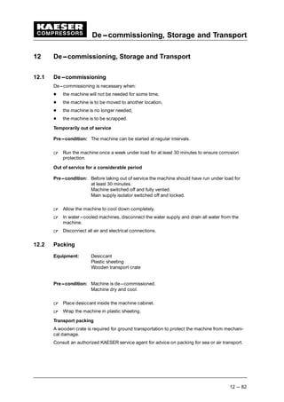
Fig. 9 Internal heat recovery 4 --- 24. . . . . . . . . . . . . . . . . . . . . . . . . . . . . . . . . . . . . . . . . . . . . . . .
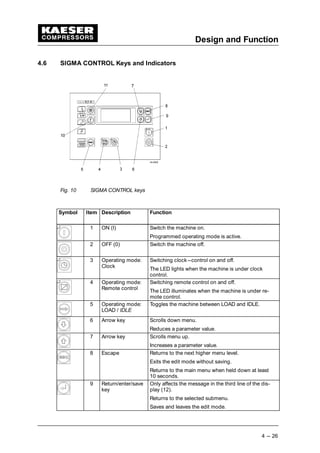
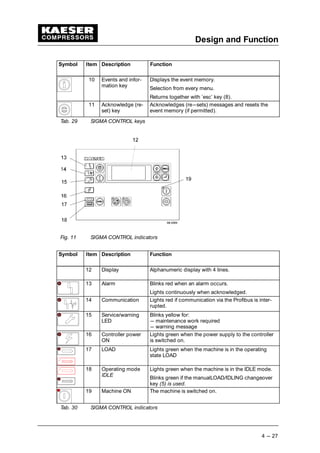
Fig. 10 SIGMA CONTROL keys 4 --- 26. . . . . . . . . . . . . . . . . . . . . . . . . . . . . . . . . . . . . . . . . . . . . .
Fig. 11 SIGMA CONTROL indicators 4 --- 27. . . . . . . . . . . . . . . . . . . . . . . . . . . . . . . . . . . . . . . . . .
Fig. 12 Installation recommendation, dimensions [in] 5 --- 29. . . . . . . . . . . . . . . . . . . . . . . . . . . .
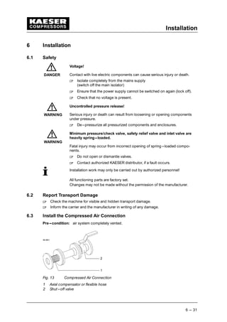
Fig. 13 Compressed Air Connection 6 --- 31. . . . . . . . . . . . . . . . . . . . . . . . . . . . . . . . . . . . . . . . . .
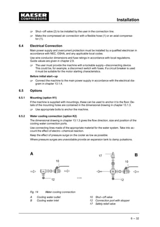
Fig. 14 Water cooling connection 6 --- 32. . . . . . . . . . . . . . . . . . . . . . . . . . . . . . . . . . . . . . . . . . . . .
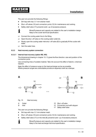
Fig. 15 Heat recovery 6 --- 33. . . . . . . . . . . . . . . . . . . . . . . . . . . . . . . . . . . . . . . . . . . . . . . . . . . . . . .
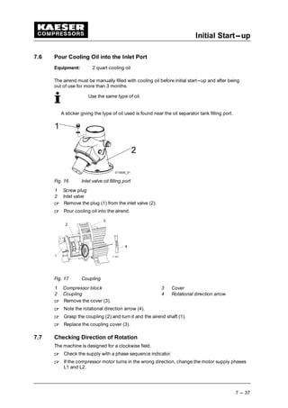
Fig. 16 Inlet valve oil filling port 7 --- 37. . . . . . . . . . . . . . . . . . . . . . . . . . . . . . . . . . . . . . . . . . . . . . .
Fig. 17 Coupling 7 --- 37. . . . . . . . . . . . . . . . . . . . . . . . . . . . . . . . . . . . . . . . . . . . . . . . . . . . . . . . . . .
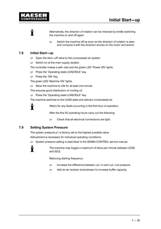
Fig. 18 Switching On and Off 8 --- 39. . . . . . . . . . . . . . . . . . . . . . . . . . . . . . . . . . . . . . . . . . . . . . . .
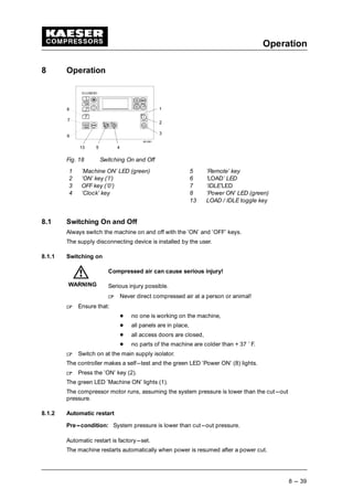
Fig. 19 Switching off in an emergency 8 --- 40. . . . . . . . . . . . . . . . . . . . . . . . . . . . . . . . . . . . . . . . .
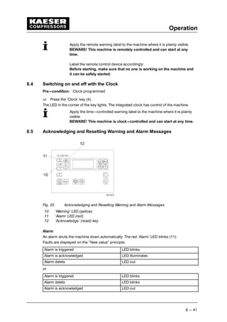
Fig. 20 Acknowledging and Resetting Warning and Alarm Messages 8 --- 41. . . . . . . . . . . . . . .
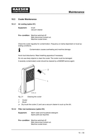
Fig. 21 Cleaning the cooler 10 --- 55. . . . . . . . . . . . . . . . . . . . . . . . . . . . . . . . . . . . . . . . . . . . . . . . . .
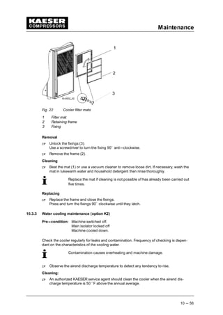
Fig. 22 Cooler filter mats 10 --- 56. . . . . . . . . . . . . . . . . . . . . . . . . . . . . . . . . . . . . . . . . . . . . . . . . . . .
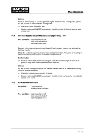
Fig. 23 Air filter maintenance. 10 --- 58. . . . . . . . . . . . . . . . . . . . . . . . . . . . . . . . . . . . . . . . . . . . . . . .
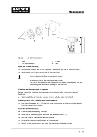
Fig. 24 Control cabinet ventilator 10 --- 59. . . . . . . . . . . . . . . . . . . . . . . . . . . . . . . . . . . . . . . . . . . . .
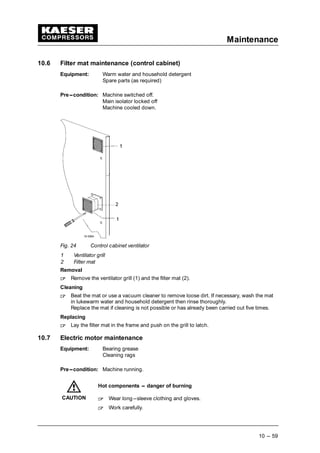
Fig. 25 Compressor motor maintenance 10 --- 60. . . . . . . . . . . . . . . . . . . . . . . . . . . . . . . . . . . . . . .
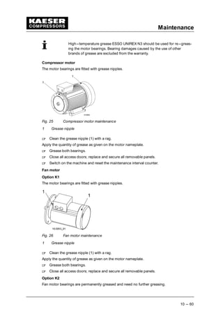
Fig. 26 Fan motor maintenance 10 --- 60. . . . . . . . . . . . . . . . . . . . . . . . . . . . . . . . . . . . . . . . . . . . . .
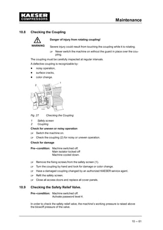
Fig. 27 Checking the Coupling 10 --- 61. . . . . . . . . . . . . . . . . . . . . . . . . . . . . . . . . . . . . . . . . . . . . . .
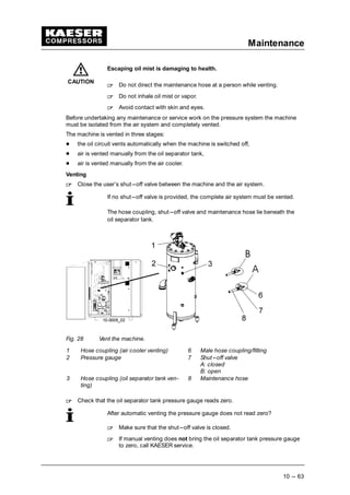
Fig. 28 Vent the machine. 10 --- 63. . . . . . . . . . . . . . . . . . . . . . . . . . . . . . . . . . . . . . . . . . . . . . . . . . .
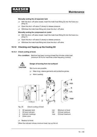
Fig. 29 Check cooling oil level. 10 --- 64. . . . . . . . . . . . . . . . . . . . . . . . . . . . . . . . . . . . . . . . . . . . . . .
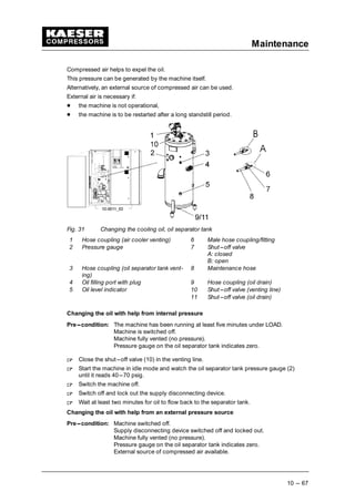
Fig. 30 Topping up the cooling oil 10 --- 65. . . . . . . . . . . . . . . . . . . . . . . . . . . . . . . . . . . . . . . . . . . .
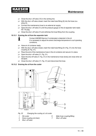
Fig. 31 Changing the cooling oil, oil separator tank 10 --- 67. . . . . . . . . . . . . . . . . . . . . . . . . . . . . .
Fig. 32 Changing the cooling oil, oil cooler 10 --- 68. . . . . . . . . . . . . . . . . . . . . . . . . . . . . . . . . . . . .
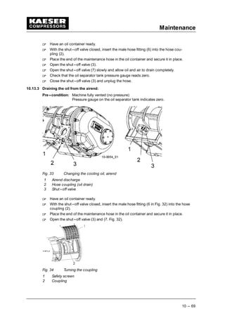
Fig. 33 Changing the cooling oil, airend 10 --- 69. . . . . . . . . . . . . . . . . . . . . . . . . . . . . . . . . . . . . . .
Fig. 34 Turning the coupling 10 --- 69. . . . . . . . . . . . . . . . . . . . . . . . . . . . . . . . . . . . . . . . . . . . . . . . .
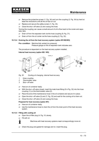
Fig. 35 Cooling oil changing, internal heat recovery 10 --- 70. . . . . . . . . . . . . . . . . . . . . . . . . . . . .
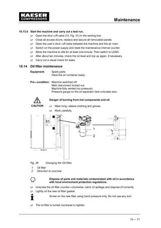
Fig. 36 Changing the Oil Filter 10 --- 71. . . . . . . . . . . . . . . . . . . . . . . . . . . . . . . . . . . . . . . . . . . . . . .
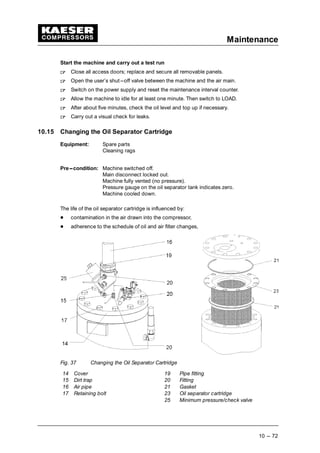
Fig. 37 Changing the Oil Separator Cartridge 10 --- 72. . . . . . . . . . . . . . . . . . . . . . . . . . . . . . . . . . .
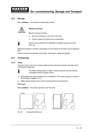
Fig. 38 Transport by fork truck 12 --- 83. . . . . . . . . . . . . . . . . . . . . . . . . . . . . . . . . . . . . . . . . . . . . . .
Fig. 39 Transport with lifting cradle 12 --- 84. . . . . . . . . . . . . . . . . . . . . . . . . . . . . . . . . . . . . . . . . . .](https://image.slidesharecdn.com/compresor-kaeser-csd100-ingl-150819104147-lva1-app6892/85/Compresor-kaeser-csd100-ingl-7-320.jpg)
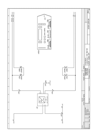
![Table Directory
Chapter --- page
vi
Tab. 1 Nameplate 2 --- 3. . . . . . . . . . . . . . . . . . . . . . . . . . . . . . . . . . . . . . . . . . . . . . . . . . . . . . . . .
Tab. 2 Options 2 --- 3. . . . . . . . . . . . . . . . . . . . . . . . . . . . . . . . . . . . . . . . . . . . . . . . . . . . . . . . . . . .
Tab. 3 Machine weights 2 --- 3. . . . . . . . . . . . . . . . . . . . . . . . . . . . . . . . . . . . . . . . . . . . . . . . . . . .
Tab. 4 Machine temperatures 2 --- 4. . . . . . . . . . . . . . . . . . . . . . . . . . . . . . . . . . . . . . . . . . . . . . .
Tab. 5 Ambient Conditions 2 --- 4. . . . . . . . . . . . . . . . . . . . . . . . . . . . . . . . . . . . . . . . . . . . . . . . . .
Tab. 6 Safety relief valve setting 2 --- 4. . . . . . . . . . . . . . . . . . . . . . . . . . . . . . . . . . . . . . . . . . . . .
Tab. 7 Capacitiy at rated pressure [CFM FAD] 2 --- 4. . . . . . . . . . . . . . . . . . . . . . . . . . . . . . . . .
Tab. 8 Sound Pressure Level 2 --- 5. . . . . . . . . . . . . . . . . . . . . . . . . . . . . . . . . . . . . . . . . . . . . . . .
Tab. 9 Compressor motor data 2 --- 5. . . . . . . . . . . . . . . . . . . . . . . . . . . . . . . . . . . . . . . . . . . . . .
Tab. 10 Fan motor data (option K1) 2 --- 5. . . . . . . . . . . . . . . . . . . . . . . . . . . . . . . . . . . . . . . . . . .
Tab. 11 Fan motor data (option K2) 2 --- 5. . . . . . . . . . . . . . . . . . . . . . . . . . . . . . . . . . . . . . . . . . .
Tab. 12 Cooling oil volumes 2 --- 7. . . . . . . . . . . . . . . . . . . . . . . . . . . . . . . . . . . . . . . . . . . . . . . . . .
Tab. 13 Supply 208V/3/60Hz 2 --- 8. . . . . . . . . . . . . . . . . . . . . . . . . . . . . . . . . . . . . . . . . . . . . . . . .
Tab. 14 Supply 230V/3/60Hz 2 --- 8. . . . . . . . . . . . . . . . . . . . . . . . . . . . . . . . . . . . . . . . . . . . . . . . .
Tab. 15 Supply 380V/3/60Hz 2 --- 8. . . . . . . . . . . . . . . . . . . . . . . . . . . . . . . . . . . . . . . . . . . . . . . . .
Tab. 16 Supply 460V/3/60Hz 2 --- 8. . . . . . . . . . . . . . . . . . . . . . . . . . . . . . . . . . . . . . . . . . . . . . . . .
Tab. 17 Supply 575V/3/60Hz 2 --- 9. . . . . . . . . . . . . . . . . . . . . . . . . . . . . . . . . . . . . . . . . . . . . . . . .
Tab. 18 Water cooling design data (30 ˚ F) 2 --- 9. . . . . . . . . . . . . . . . . . . . . . . . . . . . . . . . . . . . .
Tab. 19 Water cooling design data (70 ˚ F) 2 --- 9. . . . . . . . . . . . . . . . . . . . . . . . . . . . . . . . . . . . .
Tab. 20 Cooler specification; water cooling 2 --- 9. . . . . . . . . . . . . . . . . . . . . . . . . . . . . . . . . . . . .
Tab. 21 Cooling Water Quality 2 --- 10. . . . . . . . . . . . . . . . . . . . . . . . . . . . . . . . . . . . . . . . . . . . . . . .
Tab. 22 Heat capacity (option W1) 2 --- 10. . . . . . . . . . . . . . . . . . . . . . . . . . . . . . . . . . . . . . . . . . . .
Tab. 23 Water Quality Specification 2 --- 11. . . . . . . . . . . . . . . . . . . . . . . . . . . . . . . . . . . . . . . . . . .
Tab. 24 General specification of the heat exchanger 2 --- 11. . . . . . . . . . . . . . . . . . . . . . . . . . . . .
Tab. 25 Flow rate and heat available (option W2) 2 --- 11. . . . . . . . . . . . . . . . . . . . . . . . . . . . . . . .
Tab. 26 Flow rate and heat available (option W3) 2 --- 12. . . . . . . . . . . . . . . . . . . . . . . . . . . . . . . .
Tab. 27 Danger zones 3 --- 17. . . . . . . . . . . . . . . . . . . . . . . . . . . . . . . . . . . . . . . . . . . . . . . . . . . . . . .
Tab. 28 Safety signs 3 --- 18. . . . . . . . . . . . . . . . . . . . . . . . . . . . . . . . . . . . . . . . . . . . . . . . . . . . . . . .
Tab. 29 SIGMA CONTROL keys 4 --- 27. . . . . . . . . . . . . . . . . . . . . . . . . . . . . . . . . . . . . . . . . . . . . .
Tab. 30 SIGMA CONTROL indicators 4 --- 27. . . . . . . . . . . . . . . . . . . . . . . . . . . . . . . . . . . . . . . . . .
Tab. 31 Ventilation (option K1) 5 --- 29. . . . . . . . . . . . . . . . . . . . . . . . . . . . . . . . . . . . . . . . . . . . . . . .
Tab. 32 Ventilation (option K2) 5 --- 30. . . . . . . . . . . . . . . . . . . . . . . . . . . . . . . . . . . . . . . . . . . . . . . .
Tab. 33 Checklist, installation conditions 7 --- 36. . . . . . . . . . . . . . . . . . . . . . . . . . . . . . . . . . . . . . .
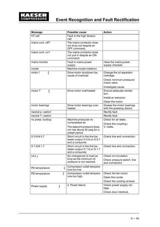
Tab. 34 Alarm messages and actions 9 --- 46. . . . . . . . . . . . . . . . . . . . . . . . . . . . . . . . . . . . . . . . . .
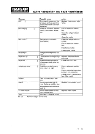
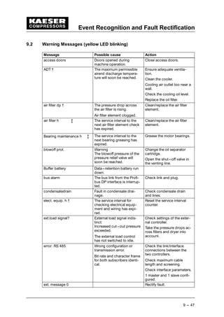
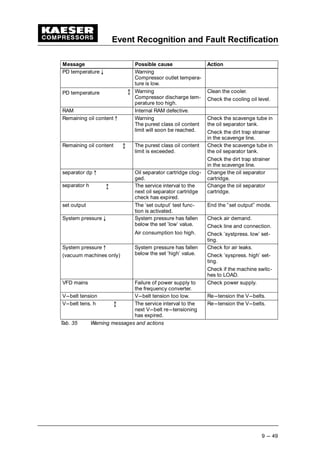
Tab. 35 Warning messages and actions 9 --- 49. . . . . . . . . . . . . . . . . . . . . . . . . . . . . . . . . . . . . . . .
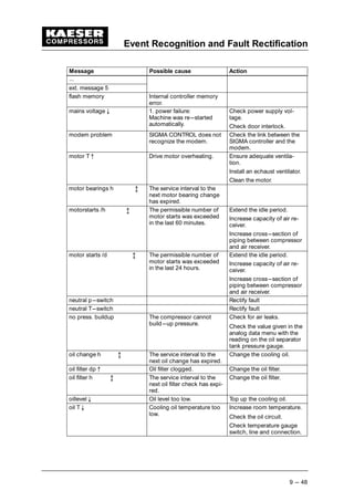
Tab. 36 Miscellaneous events (faults) 9 --- 50. . . . . . . . . . . . . . . . . . . . . . . . . . . . . . . . . . . . . . . . . .
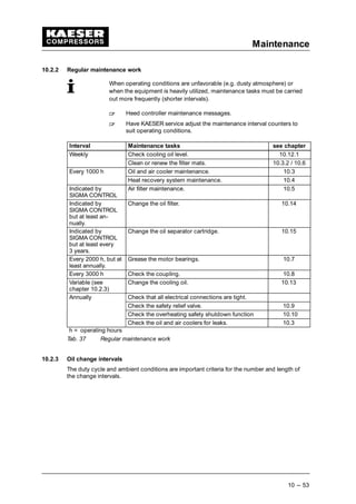
Tab. 37 Regular maintenance work 10 --- 53. . . . . . . . . . . . . . . . . . . . . . . . . . . . . . . . . . . . . . . . . . . .
Tab. 38 Oil change intervals lubricants 10 --- 54. . . . . . . . . . . . . . . . . . . . . . . . . . . . . . . . . . . . . . . . .
Tab. 39 Oil change intervals speciality lubricants 10 --- 54. . . . . . . . . . . . . . . . . . . . . . . . . . . . . . . .
Tab. 40 Regular service intervals 10 --- 54. . . . . . . . . . . . . . . . . . . . . . . . . . . . . . . . . . . . . . . . . . . . . .
Tab. 41 Maintenance log 10 --- 74. . . . . . . . . . . . . . . . . . . . . . . . . . . . . . . . . . . . . . . . . . . . . . . . . . . .
Tab. 42 Machine maintenance parts 11 --- 75. . . . . . . . . . . . . . . . . . . . . . . . . . . . . . . . . . . . . . . . . . .](https://image.slidesharecdn.com/compresor-kaeser-csd100-ingl-150819104147-lva1-app6892/85/Compresor-kaeser-csd100-ingl-8-320.jpg)
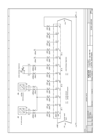
![Technical Specification
2 --- 3
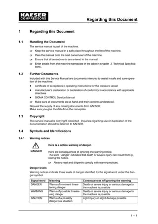
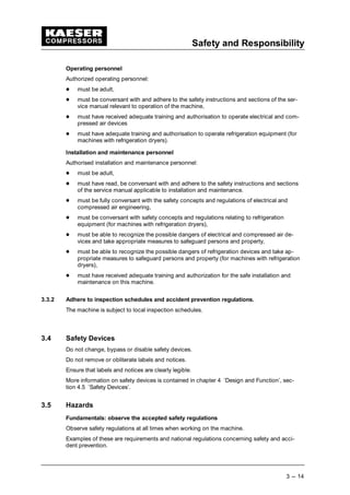
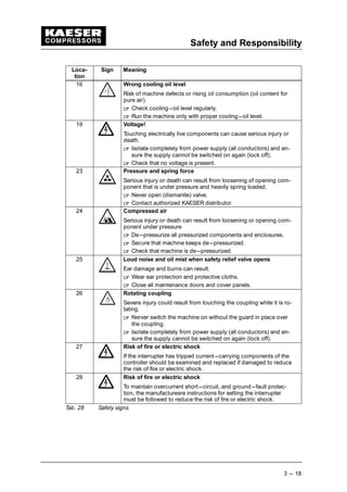
2 Technical Specification
Model and important technical information is to be found on the machine nameplate. The
nameplate is found inside the machine. It is fixed to the outside of the control cabinet.
Please transfer data from the nameplate.
Model
Part no.
Year
Serial no.
psig
cfm
Voltage
Hz/RPM
Package FLA
Phase
HP
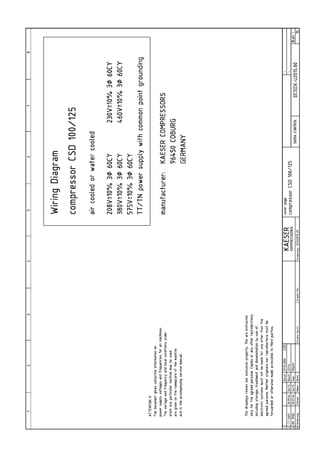
Wiring Diagram
FOR SERVICE, REFER TO EQIPMENT
NUMBER
Tab. 1 Nameplate
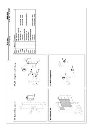
A summary of the included options helps to relate the service manual information to your
machine.
Please enter details of options.
Option Code Exists
Air cooled K1
Water cooled K2
Filter mat panels K3
Machine mountings H1
Prepared for heat recovery W1
Internal heat recovery
T= 25K W2
Internal heat recovery
T= 55K W3
Modulation control C1
Transformer power supply for refrigeration
dryer
T2
Tab. 2 Options
2.1 Weight
Maximum weights are shown. Actual weights of individual machines are dependent on
equipment fitted.
CSD 100 CSD 125
Weight [lb] 4235 4455
Tab. 3 Machine weights](https://image.slidesharecdn.com/compresor-kaeser-csd100-ingl-150819104147-lva1-app6892/85/Compresor-kaeser-csd100-ingl-11-320.jpg)
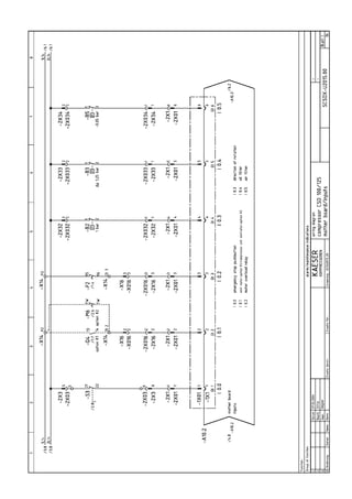
![Technical Specification
2 --- 4
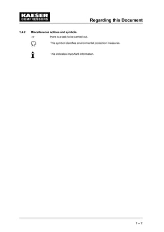
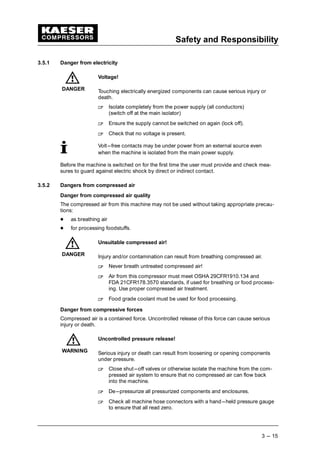
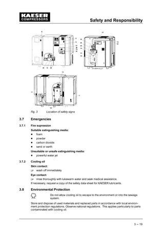
2.2 Temperature
CSD 100 CSD 125
Minimum cut---in temperature
[˚ F]
40 40
Typical airend discharge tem-
perature during operation [˚ F]
167 --- 200 167 --- 200
Max. airend discharge temp.
(automatic shut---down) [˚ F]
230 230
Tab. 4 Machine temperatures
2.3 Ambient Conditions
CSD 100 CSD 125
Maximum elevation [ft] 3000 3000
Ambient temperature [˚ F] 40 – 115 40 – 115
Inlet air / cooling air tempera-
ture [˚ F]
40 – 115 40 – 115
Humidity of the inlet air at
90 ˚ F [%]
100 100
Humidity of the inlet air at
113 ˚ F [%]
50 50
* Higher elevation permissible only after consultation with the manufacturer
Tab. 5 Ambient Conditions
2.4 Pressure
See nameplate for maximum working pressure.
Maximum working pressure
[psig]
Blow---off setting of the safety relief valve [psig]
CSD 100 CSD 125
125 155 155
160 230 230
217 230 230
Tab. 6 Safety relief valve setting
2.5 Free Air Delivery (FAD)
Rated pressure [psig] CSD 100 CSD 125
110 506 584
125 503 581
145 420 498
160 417 494
175 348 414
190 345 411
217 337 406
Tab. 7 Capacitiy at rated pressure [CFM FAD]](https://image.slidesharecdn.com/compresor-kaeser-csd100-ingl-150819104147-lva1-app6892/85/Compresor-kaeser-csd100-ingl-12-320.jpg)
![Technical Specification
2 --- 5
2.6 Sound Pressure Level
Operational state
under load at rated speed, rated delivery and rated pressure.
Measuring conditions:
Free---field measurement to CAGI/PNEUROP PN8 NTC 2.3 at 1 m distance
CSD 100 CSD 125
Sound pressure level (60Hz) [dB(A)] 73 74
Tab. 8 Sound Pressure Level
2.7 Motor and Performance
2.7.1 Compressor motor:
CSD 100 CSD 125
Rated power [Hp] 100 125
Rated speed [rpm] 3580 3582
Enclosure protection TEFC TEFC
Motor bearing greasing
[operating hours]
2000 2000
Grease requirement, each bearing
[oz]*
* Transfer data from motor nameplate to the table
Tab. 9 Compressor motor data
2.7.2 Fan Motor
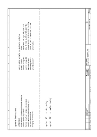
Air cooling (option K1)
CSD 100 CSD 125
Rated power [Hp] 3 3
Rated speed [rpm] 1170 1170
Enclosure protection TEFC TEFC
Motor bearing greasing
[operating hours]
2000 2000
Grease requirement, each bearing
[oz]*
* Transfer data from motor nameplate to the table
Tab. 10 Fan motor data (option K1)
Water cooling (option K2)
CSD 100 CSD 125
Rated power [Hp] 0.13 0.13
Rated speed [rpm] 2700 2700
Enclosure protection TEFC TEFC
Tab. 11 Fan motor data (option K2)](https://image.slidesharecdn.com/compresor-kaeser-csd100-ingl-150819104147-lva1-app6892/85/Compresor-kaeser-csd100-ingl-13-320.jpg)
![Technical Specification
2 --- 7
with the discharge air. This lubricant meets the requirements of the FDA Regulation 21
CFR §178.3570 and is USDA H---1 approved and NSF certified. FG---460 is approved
for canning, food packing, meat and poultry processing and other applications where
incidental food contact may occur.
2.8.2 Cooling Oil Quantity
CSD 100 CSD 125
Total charge [gal] (option K1) 14.5 14.5
Total charge [gal] (option K2) 11.4 11.4
Top---up volume [gal]
(minimum --- maximum
1.3 1.3
Additional volume [gal] (option W2) 1.9 1.9
Additional volume [gal] (option W3) 1.2 1.2
Additional volume [gal] (option W1) *
* Input the additional volume corresponding to your heat recovery system.
Tab. 12 Cooling oil volumes
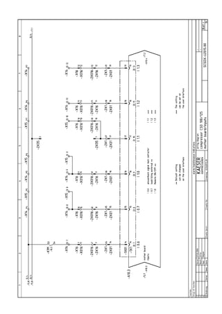
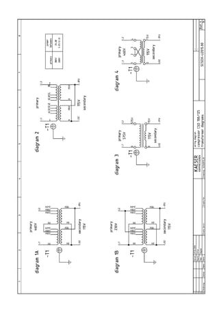
2.9 Electrical Connections
See electrical diagrams in chapter 13.1.4.
2.9.1 Power supply
The machine is designed for an electrical supply according to National Electric Code
(NEC) NEC---670, particulary NFPA 79, section 5.7. In the absence of any user---specified
alternatives, the limits given in these standards must be adhered to. Consult manufacturer
for any other specific power supply.
Three---phase
Do NOT operate package on any unsymmetrical power supply. Also do NOT operate pack-
age on power supplies like, for example, a three---phase (open) delta or three---phase star
with non---earthed neutral.
Fig. 1 Three---phase star (wye); four wire; earthed neutral
Fig. 2 Three---phase star (wye); three wire; earthed neutral
The machine requires a symmetrical three---phase power supply transformer with a WYE
configuration output as shown in Fig. 1 and Fig. 2.
In a symmetrical three phase supply the phase angles and voltages are all the same.
Other power supplies are not suitable. Please contact authorized KAESER distributor for
options.](https://image.slidesharecdn.com/compresor-kaeser-csd100-ingl-150819104147-lva1-app6892/85/Compresor-kaeser-csd100-ingl-15-320.jpg)
![Technical Specification
2 --- 8
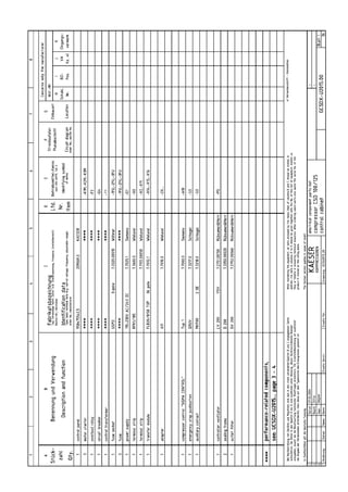
2.9.2 Power supply specifications
The following multi---strand copper core wires are given according to 2002 NEC 310---15,
Table 310---16 for 40 ˚ C ambient temperature.
If other local conditions prevail, like for example high temperature, the cross section should
be checked and adjusted according to 2002 NEC 110---14
, 220---3,310---15, Table
310---16, 430---6, 430---22, 430---24 and other local codes.
Dual element time delay fuses are selected according to 2002 NEC 240---6,430---52 and
tables 430---52, 430---148 and 430---150.
We strongly suggest using a separate copper conductor for the equipment GROUNDING.
NEC Table 250.122 will point out the ”minimum size”, however, we recommend a ground
conductor the same size as the power leads, if local codes allow.
Rated power supply 208V ¡ 10%, 3---ph, 60Hz
CSD 100 CSD 125
Pre---fuse [A] 450 500
Supply 2x 4xAWG4/0 2x 4xMCM250
Consumption [A] (Option K1) 320 354
Consumption [A] (Option K2) 310 345
Tab. 13 Supply 208V/3/60Hz
Rated power supply 230V ¡ 10%, 3---ph, 60Hz
CSD 100 CSD 125
Pre---fuse [A] 400 450
Supply 2x 4xAWG4/0 2x 4xAWG4/0
Consumption [A] (Option K1) 288 320
Consumption [A] (Option K2) 279 311
Tab. 14 Supply 230V/3/60Hz
Rated power supply 380V ¡ 10%, 3---ph, 60Hz
CSD 100 CSD 125
Pre---fuse [A] 250 250
Supply 4xMCM250 4xMCM300
Consumption [A] (Option K1) 175 195
Consumption [A] (Option K2) 169 190
Tab. 15 Supply 380V/3/60Hz
Rated power supply 460V ¡ 10%, 3---ph, 60Hz
CSD 100 CSD 125
Pre---fuse [A] 200 225
Supply 4xAWG4/0 4xAWG4/0
Consumption [A] (Option K1) 146 160
Consumption [A] (Option K2) 142 157
Tab. 16 Supply 460V/3/60Hz
Rated power supply 575V ¡ 10%, 3---ph, 60Hz
CSD 100 CSD 125
Pre---fuse [A] 150 175
Supply 4xAWG2/0 4xAWG3/0](https://image.slidesharecdn.com/compresor-kaeser-csd100-ingl-150819104147-lva1-app6892/85/Compresor-kaeser-csd100-ingl-16-320.jpg)
![Technical Specification
2 --- 9
CSD 125CSD 100
Consumption [A] (Option K1) 115 128
Consumption [A] (Option K2) 112 125
Tab. 17 Supply 575V/3/60Hz
2.10 Water cooling (option K2)
2.10.1 Design data
Cooling water temperature rise 30 ˚ F
CSD 100 CSD 125
Max. permissible inlet temperature
[˚ F]
90 90
Min. cooling water flow [gpm] 26.4 31.9
Water pressure drop [psig] 15 20
Tab. 18 Water cooling design data (30 ˚ F)
Cooling water temperature rise 70 ˚ F
CSD 100 CSD 125
Max. permissible inlet temperature
[˚ F]
50 50
Min. cooling water flow [gpm] 8.8 10.6
Water pressure drop [psig] 7 7
Tab. 19 Water cooling design data (70 ˚ F)
Cooler specification
Material of manufacture 1.4401
Solder Copper
Maximum working pressure (cooling water
end) [psig]
145
Unsuitable cooling medium Seawater
Consult KAESER before using cooling wa-
ter solutions
Max. permissible discharge temperature
[˚ F]
158
Tab. 20 Cooler specification; water cooling
2.10.2 Cooling Water Quality
Do not use the cooling water as drinking water.
If a leak occurs, oil can contaminate the cooling water.
Measures for cooling water treatment and filtration are essential and must be carried out.
The addresses of companies specializing in the analysis of cooling water and supplying
suitable equipment for the its treatment can be obtained from KAESER on request.
To avoid operating breakdowns from a corroded or clogged cooler, the cooling water must
meet certain minimum requirements:](https://image.slidesharecdn.com/compresor-kaeser-csd100-ingl-150819104147-lva1-app6892/85/Compresor-kaeser-csd100-ingl-17-320.jpg)
![Technical Specification
2 --- 10
pH value 7.5 to 9.0
Hardness [ dH] 4.0---8.5
Chloride (Cl) [mg/l] < 150
Free chlorine gas (Cl2) [mg/l] < 1
Sulphate (SO3) [mg/l] < 1
Dissolved iron (Fe) [mg/l] < 0.2
Hydrogen carbonate (HCO3) [mg/l] 70---300
Sulphate (SO4) [mg/l] < 70
HCO3 / SO4 > 1
Electrical conductivity [ S/cm] 10---500
Ammonia (NH3) [mg/l] < 2
Dissolved magnesium (Mn) [mg/l] < 0.1
Dissolved aluminium (Al) [mg/l] < 0.2
Nitrate (NO3), dissolved [mg/l] < 100
Hydrogen sulphate (SO2) [mg/l] < 0.05
Free aggressive carbon dioxide (CO2) [mg/l] < 5
Glycol [%] < 50
Solids (particle size) [mm] < 0.1
Algae not permissible
Tab. 21 Cooling Water Quality
2.11 Heat Recovery
2.11.1 Prepared for heat recovery (option W1)
Connections for an external heat recovery system are provided.
Heat capacity
CSD 100 CSD 125
Max. heat capacity available [kW] 40.3 49.4
Max. heat capacity available [MJ/h] 145 178
Max. heat capacity available [kcal/h] 34669 42511
Tab. 22 Heat capacity (option W1)
2.11.2 Internal Heat Recovery (option W2 / W3)
A soldered, plate heat exchanger is installed for heat recovery.
Generally water is used as the heat transfer medium. This must conform to the specifica-
tion given below.
The water may not be used as drinking water.
If a leak occurs, oil can contaminate the water.
The manufacturer should be consulted before another type of heat transfer
medium is used.
Water Quality Specification
pH value 7.5 to 9
Hardness [ dH] 4.0---8.5](https://image.slidesharecdn.com/compresor-kaeser-csd100-ingl-150819104147-lva1-app6892/85/Compresor-kaeser-csd100-ingl-18-320.jpg)
![Technical Specification
2 --- 11
Chloride (Cl)* [mg/l] < 150
Free chlorine gass (Cl2) [mg/l] < 1
Sulphate (SO3) [mg/l] < 1
Dissolved iron (Fe) [mg/l] < 0.2
Hydrogen carbonate (HCO3) [mg/l] 70---300
Sulphate (SO4) [mg/l] < 70
HCO3 / SO4 > 1
Electrical conductivity [ S/cm] 10---500
Ammonia (NH3) [mg/l] < 2
Dissolved magnesium (Mn) [mg/l] < 0.1
Dissolved aluminium (Al) [mg/l] < 0.2
Nitrate (NO3), dissolved [mg/l] < 100
Hydrogen sulphate (SO2) [mg/l] < 0.05
Free aggressive carbon dioxide (CO2) [mg/l] < 5
Glycol [%] < 50
Solids (particle size) [mm] < 0.1
Algae not permissible
Tab. 23 Water Quality Specification
If the heat transfer medium outlet temperature is to be kept constant, the
user must install an appropriate regulating device.
Heat Exchanger Specification
CSD 100 CSD 125
Maximum working pressure of the
heat transfer medium [psig]
145 145
Pressure drop [psig] < 1.5 < 1.5
Plate material 1.4401 1.4401
Solder Cu Cu
Maximum permissible temperature of
the heat transfer medium [˚ F]
210 210
Tab. 24 General specification of the heat exchanger
Flow rate and heat capacity by heating from 110 ˚ F to 160 ˚ F (equivalent to ¡ T= 25 K),
(option W2)
CSD 100 CSD 125
Flow rate [gpm] 9.7 11.9
Max. heat capacity available [kW] 40.3 49.4
Max. heat capacity available [MJ/h] 145 178
Max. heat capacity available [kcal/h] 34669 42511
Tab. 25 Flow rate and heat available (option W2)
Flow rate and heat capacity by heating from 60 ˚ F to 160 ˚ F (equivalent to ¡ T= 55 K),
(option W3)
CSD 100 CSD 125
Flow rate [gpm] 4.4 5.3
Max. heat capacity available [kW] 40.3 49.4](https://image.slidesharecdn.com/compresor-kaeser-csd100-ingl-150819104147-lva1-app6892/85/Compresor-kaeser-csd100-ingl-19-320.jpg)
![Technical Specification
2 --- 12
CSD 125CSD 100
Max. heat capacity available [MJ/h] 145 178
Max. heat capacity available [kcal/h] 34669 42511
Tab. 26 Flow rate and heat available (option W3)](https://image.slidesharecdn.com/compresor-kaeser-csd100-ingl-150819104147-lva1-app6892/85/Compresor-kaeser-csd100-ingl-20-320.jpg)
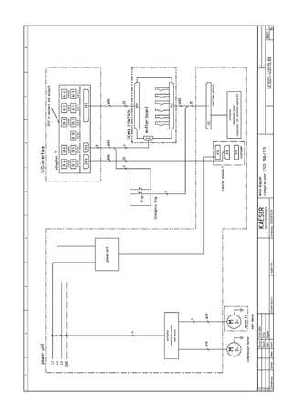
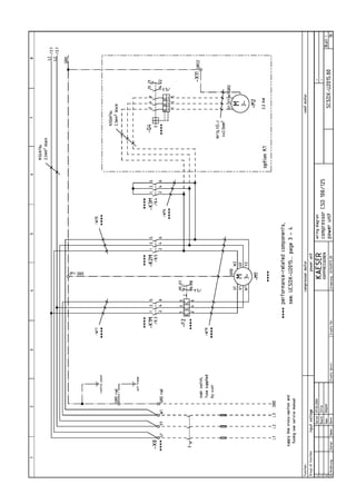
![Design and Function
4 --- 21
4.1.2 Function
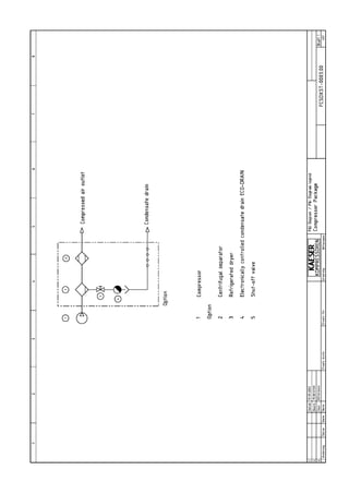
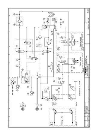
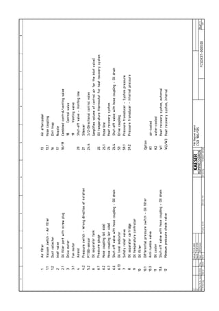
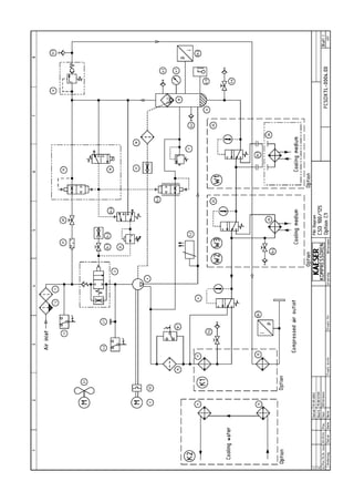
Items in brackets [ ] correspond to the Pipe and Instrument Flow Diagram (P & I Diagram)
in chapter 13.1.1.
An air---cooled machine serves to illustrate function.
Fig. 5 Air---cooled machine
1 Inlet valve [2] 6 Control cabinet
2 Coupling [5] 7 Oil separator tank [6]
3 Compressor motor [3] 8 Air filter [1]
4 Oil filter [10] 9 Oil/air cooler [11/13]
5 Airend [4]
Compressor
Atmospheric air is cleaned as it is drawn in through the filter (8).
The air is then compressed in the airend (5).
The airend is driven by an electric motor (3).
Cooling oil is injected into the airend. It lubricates moving parts and forms a seal between
the rotors themselves and between them and the airend casing. The cooling effect directly
within the compression chamber ensures a low airend discharge temperature.
Cooling oil is recovered from the compressed air in the oil separator tank (7) and is then
cooled in the oil cooler (9). The oil then flows through the filter (4) and back to the point of
injection. Air pressure within the machine keeps the oil circulating and therefore a separate
pump is not necessary. A thermostatic valve maintains optimum oil temperature.
Compressed air, freed of its oil content in the separator tank (7), flows through the mini-
mum pressure/check valve into the aftercooler (9). The minimum pressure/check valve en-
sures there is always sufficient air pressure to maintain cooling oil circulation.
The aftercooler brings down the compressed air temperature to 5 to 10 K above ambient.
Most of the moisture carried in the air is removed in the aftercooler.](https://image.slidesharecdn.com/compresor-kaeser-csd100-ingl-150819104147-lva1-app6892/85/Compresor-kaeser-csd100-ingl-29-320.jpg)
![Design and Function
4 --- 23
4.3 Options
4.3.1 Machine mountings (option H1)
The machine mountings enable the machine to be anchored to the floor.
Fig. 6 Machine mountings
4.3.2 Filter mat panels (option K3)
Mats filter the cooling air and keep the cooler surface clean.
Fig. 7 Filter mat panel
1 Cooling air filter mat
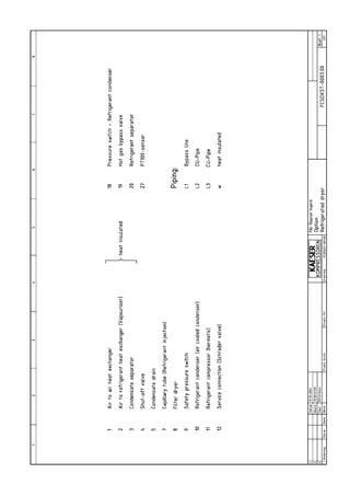
4.3.3 Water cooling (option K2)
Plate heat exchangers in stainless steel are used for water---cooled machines.
Fig. 8 Water cooling
1 Oil cooler [11] 3 Cooling water connection
2 Compressed air aftercooler [13] 4 Cooling water connection
4.3.4 Heat recovery
External heat recovery (option W1)
Connections are provided and bridged.](https://image.slidesharecdn.com/compresor-kaeser-csd100-ingl-150819104147-lva1-app6892/85/Compresor-kaeser-csd100-ingl-31-320.jpg)
![Design and Function
4 --- 24
An external heat recovery system can be retro---fitted at any time.
Internal heat recovery (option W2 / W3)
A plate heat exchanger (1) is installed for heat recovery.
Fig. 9 Internal heat recovery
1 Plate heat exchanger [26]
4.4 Operating States and Control Modes
4.4.1 Operating states
There are three operating states:
LOAD: the inlet valve is open. The airend delivers compressed air to the system.
The compressor motor runs under full load.
IDLING: The inlet valve is closed. The minimum pressure/check valve shuts off the oil
separator from the air system. The oil separator tank is vented.
A small volume of air circulates through the bleed hole in the inlet valve, through the
airend and back to the inlet valve via the venting valve.
The compressor motor runs without load and draws little current.
STANDSTILL: The inlet valve is closed. The minimum pressure/check valve shuts off
the oil separator from the air system. The oil separator tank is vented.
The compresor motor is stopped.
MODULATION CONTROL (option C1): The proportional controller continuously varies
the degree of opening of the inlet valve, and thereby the delivery rate of the compres-
sor, in response and in proportion to the air demand. The airend delivers compressed
air to the system.
The load and power consumption of the compressor motor rises and falls with the air
demand.
The regulating valve is factory set. Consult with KAESER Service before changing.
4.4.2 Controller Operation
Using the selected control mode, the controller switches the compressor between its vari-
ous operational states in order to maintain system pressure between the set minimum and
maximum values.
According to the individual compressed air demand one of the various control modes avail-
able will provide the optimum duty cycle for the machine.
4.4.3 Control Modes
The controller can operate in the following modes:
DUAL
VARIO
QUADRO](https://image.slidesharecdn.com/compresor-kaeser-csd100-ingl-150819104147-lva1-app6892/85/Compresor-kaeser-csd100-ingl-32-320.jpg)
![Installation and Operating Conditions
5 --- 29
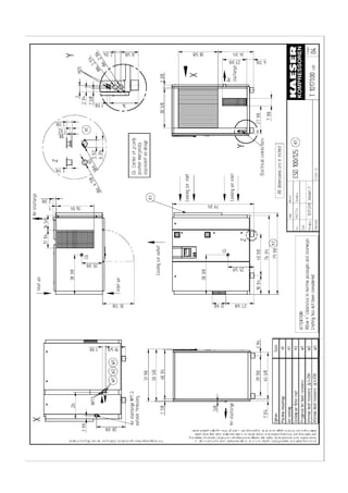
Fig. 12 Installation recommendation, dimensions [in]
A Exhaust fan
B Exhaust air duct
Z Inlet air opening
5.2.2 Ventilation
Values given are minimum guidelines.
If the inlet aperture is insufficient a dangerous vacuum can be created in
the compressor room.
Ensure that the volume of air flowing into the compressor room is at
least equivalent to that being removed from it by the machine and
exhaust fan.
Make sure that the machine and exhaust fan can only operate when
the inlet aperture is actually open.
Option K1:
CSD 100 CSD 125
Inlet opening [sq.ft.] 20 24
Forced ventilation with exhaust venti-
lator: Flow rate [cfm] at 0.4 in wc
14714 17657
Exhaust air duct:
Dimensions [in]
39 3/8 x 39 3/8 39 3/8 x 39 3/8
Tab. 31 Ventilation (option K1)](https://image.slidesharecdn.com/compresor-kaeser-csd100-ingl-150819104147-lva1-app6892/85/Compresor-kaeser-csd100-ingl-37-320.jpg)
![Installation and Operating Conditions
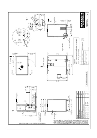
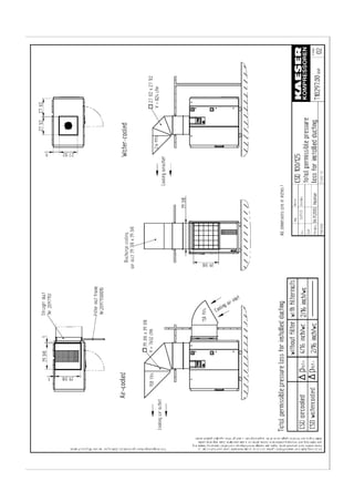
5 --- 30
Option K2:
CSD 100 CSD 125
Inlet opening [sq.ft.] 3.2 3.2
Forced ventilation with exhaust venti-
lator: Flow rate [cfm] at 0.4 in wc
1766 1766
Exhaust air duct:
Dimensions [in]
27 1/2 x 27 1/2 27 1/2 x 27 1/2
Tab. 32 Ventilation (option K2)
Exhaust ducting
Consult the manufacturer on the design of the ducting, length, number of bends, etc.
Further information on exhaust air ducts can be found in chapter 13.1.3.
5.2.3 Operating in a compressed air system
When the machine is connected to an air system, the operating pressure must not exceed
230 psig.
Initial filling of a fully vented air system generally creates a very high rate of flow through air
treatment devices. These conditions are detrimental to correct air treatment. Air quality can
be degraded.
To ensure maintenance of desired air quality when filling a vented air system we recom-
mend the installation of an air main charging system.
Please contact KAESER for assistance in selecting and installing an air main charging sys-
tem.](https://image.slidesharecdn.com/compresor-kaeser-csd100-ingl-150819104147-lva1-app6892/85/Compresor-kaeser-csd100-ingl-38-320.jpg)
![Spares, Operating Materiels, Service
11 --- 75
11 Spares, Operating Materials, Service
11.1 Note the nameplate
Please quote the data on the nameplate for all inquiries and spare parts orders.
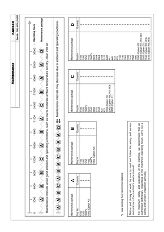
11.2 Ordering Maintenance Parts and Operating Materials
Personal injury or machine damage may result from the use of unsuit-
able spare parts or operating materials.
Unsuitable or poor quality maintenance parts and operating materials may
damage the machine or impair its proper function.
Damage to the machine can also result in personal injury.
Use only genuine spare parts and authorized operating materials.
Have an authorized KAESER service agent carry out regular mainte-
nance.
KAESER maintenance parts and operating materials correspond to the original. These are
correct for use in our machines.
Machine
Name Quantity Number
Air filter cartridge 1 1250
Filter mat (control cabinet fan) 2 1100
Filter mat (cooler) 1 1050
Oil filter 1 1200
Oil separator cartridge 1 1450
Cooling oil 1 1600
Bearing grease [g] 100 9.0915.0Bearing grease [g]
400 6.3234.0
Tab. 42 Machine maintenance parts
11.3 Maintenance Contract
Sign a maintenance contract with an authorized KAESER distirbutor.
This ensures the utmost reliability and availability of your compressed air supply system.
11.4 Service Addresses
Addresses of KAESER distributors are given at the end of this manual.
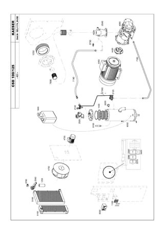
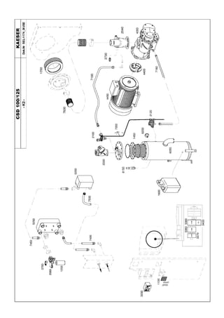
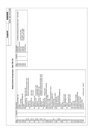
11.5 Spare Parts for Service and Repair
Any inspection, maintenance or repair tasks not described in this manual
should be carried out by an authorized KAESER distributor.
With the help of this parts list you can obtain in advance the spares you need in accor-
dance with your operating conditions.
CAUTION](https://image.slidesharecdn.com/compresor-kaeser-csd100-ingl-150819104147-lva1-app6892/85/Compresor-kaeser-csd100-ingl-83-320.jpg)