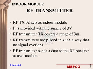
9 June 2015 19 June 2015 1
ELECTRONIC DRESS FOR NAVIGATION
OF VISUALLY CHALLENGED PERSON
By
G. NAGANANDHINI ( Reg. No. 951711106059)
R. SOPHIA DELSI ( Reg. No. 951711106097)
IV B.E ECE - C
Guided By
G. PREMA
Professor/ECE
9 June 2015 29 June 2015 2
OBJECTIVE
To provide effective assistance to increase
the mobility of the visually challenged
person in an indoor environment.
9 June 2015 39 June 2015 3
LITERATURE SURVEY – I
TITLE OF THE PAPER A Navigation System For Visually Impaired An Intelligent
White Cane
CONFERENCE A.Jin Fukasawa and Second Kazusihge Magatani
34th Annual International Conference of IEEE EMBS
San Diego,California USA
PUBLISHED YEAR 28th August- 1st September 2012
ABSTRACT It consist of:
-Coloured navigational lines with IC tags
- Intelligent white cane
Each coloured line is assigned for each destination
When color sensor finds target color , white cane informs
that he/she is on the navigational line by vibration.
DRAWBACK • Finds difficulty if there are more number of destinations
because more coloured lines are to be used.
• It cannot distinguish different color line at the cross
point of two different route
9 June 2015 49 June 2015 4
LITERATURE SURVEY – II
TITLE OF THE PAPER RFID Based Indoor Navigational Aid For Persons With
Severe Visual Impairments
CONFERENCE Andrew Y.J Szeto,Fellow IEEE and Satish K. Sharma,
Senior Member,IEEE
29th Annual International Conference of IEEE
PUBLISHED YEAR August 23-26,2007
ABSTRACT Low cost, portable navigational aid using RFID
It provides
-current location
-route to the desination
DRAWBACK •The range of RFID is small.
•More number of RFID tags has to be installed
9 June 2015 59 June 2015 5
EXISTING MODEL
 Outdoor navigation – Global Positioning
System(GPS)
 GPS provides accurate location for any
outdoor environment
 GPS receivers cannot perform well in indoor
environments because of absence of line of
sight to the satellites.
 It can provide directions, but not reliable or
accurate enough for use in buildings.
9 June 2015 69 June 2015 6
NAVIGATION SYSTEM
Major functions
 To help people travel with independence
 Sensing the immediate environment for
obstacle
 Providing information about location and
route them to reach the intended destination
9 June 2015 79 June 2015 7
CONT..
 Indoor navigation – Radio Frequency (RF)
Transmitter and Receiver
 Voice alert to avoid obstacle
 The system relies on the location
information and user’s destination.
 Voice assistance.
9 June 2015 89 June 2015 8
MODULES USED
 USER MODULE:
-Obstacle detection
-Navigational path
-Voice assistance
 INDOOR MODULE:
-Location information
9 June 2015 99 June 2015 9
BLOCK DIAGRAM
PIC 16F877a
MICROCON
TROLLER
INFRARED
SENSOR
VOICE
RECOGNI
TION KIT
HM2007
POWER
SUPPLY
VOICE
PLAYBACK
KIT
APR33A3
EAR
PHONE
RF RX
RF TX
POWER
SUPPLY
User
Module Indoor
Module
9 June 2015 1
0
9 June 2015 1
0
RF TRANSMITTER AND
RECEIVER
• RF signal can travel through a longer
distance .
• It can travel even when there is obstacle
between transmitter and receiver.
• RF TX and RX uses a specific frequency of
434MHz.
9 June 2015 1
1
9 June 2015 1
1
RF TRANSMITTER
• RF TX 02 acts as indoor module
• It is provided with the supply of 3V
• RF transmitter TX covers a range of 3m.
• RF transmitters are placed in such a way that
no signal overlaps.
• RF transmitter sends a data to the RF receiver
at user module.
INDOOR MODULE
9 June 2015 1
2
9 June 2015 1
2
RF RECEIVER
• Receiving unit is present at the user module
in the Electronic Dress.
• It consists of RF Receiver RX3304, decoder
and a buffer.
• The received signal is decoded and passed
to the buffer before being sent to the
Microcontroller.
USER MODULE
9 June 2015 1
3
9 June 2015 1
3
CONT…
• This data reveals the identity of the
transmitting RF, by means of this the
location of the user is found.
• Location information is processed by the
Microcontroller to route the user to the
intended destination.
9 June 2015 1
4
9 June 2015 1
4
No
Yes
Start
Destination is Given as Voice Input
Through HM2007
Current Location is
Sensed by RF TX
Read the Location Along the
Route by PIC16F877A
Current
Location= =
Destination
Command the User to
Proceed in the Respective
Direction
FLOWCHART- INDOOR NAVIGATION
Stop
9 June 2015 1
5
9 June 2015 1
5
MICROCONTROLLER
PIC16F877A
• It processes the signal from RF receiver.
• It provides the route to the user’s
earphone via the playback kit.
• Port RB0-RB3 is connected to the
channels of APR33A3
• Port RC0-RC3 is connected to the
receiver via buffer.
• Port RD0-RD3 is connected to the voice
recognition kit HM2007.
9 June 2015 1
6
9 June 2015 1
6
NAVIGATIONAL PATH
Wash
basin
Node A
Staff
room
Node B
Turning
point
Node C
Bio
medical
lab
Node D
9 June 2015 1
7
9 June 2015 1
7
CONT..
• At each node a RF Transmitter is placed .
• Now the user is at Node D and gives his destination as
Staff room through voice input.
• Each RF TX sends a signal to the user module based on
which he is given the directions to reach staff room.
• When the user is at Node D, he receives the voice signal as
walk straight.
• When he receives the signal from Node C , he is assisted to
turn right and walk straight.
• When the user reaches Node B, the voice output says
destination reached.
9 June 2015 1
8
9 June 2015 1
8
OBSTACLE DETECTION-
BLOCK DIAGRAM
O
B
J
E
C
T
POWER
SUPPLY
VOICE
PLAYBACK KIT
APR33A3
EARPHONE
I
R
S
E
N
S
O
R
9 June 2015 1
9
9 June 2015 1
9
OBSTACLE DETECTION USING
INFRARED SENSOR
• A pulse of IR light is emitted by the emitter.
• The light travels out into the field.
• It detects obstacle at a distance of 80cm.
• If there is no object, the light is never reflected.
• If the light hits an object, it returns to the detector.
• The received signal is given to the voice playback
kit(APR33A3) which plays the recorded voice as
obstacle detected.
9 June 2015 2
0
9 June 2015 2
0
SOFTWARE IMPLEMENTATION
9 June 2015 2
1
9 June 2015 2
1
HARDWARE IMPLEMENTATION
9 June 2015 2
2
9 June 2015 2
2
SOCIAL IMPACT
• This navigation system supports the independent
walking of the visually challenged in the indoor
space.
• It eliminates the need for a visually challenged
person to carry a walking stick.
• The directions and location information can be
useful for search and rescue operations.
9 June 2015 2
3
9 June 2015 2
3
CONCLUSION
• The design and development of electronic
dress for navigation of visually challenged
person is used for navigation in an
unfamiliar environment.
• The implementation part has been done in
Department of ECE 2nd floor of Mepco
Schlenk Engineering college.
9 June 2015 2
4
9 June 2015 2
4
FUTURE SCOPE
-“Electronic Dress for Navigation of Visually
Challenged Person” was implemented for navigation
in a particular building, for navigation in any indoor
space a microcontroller and a Bluetooth has to be
affixed at the entrance of a building.
-This section will contain the path information to
every destination in a particular building.
-When the user reaches the entrance the data from the
controller in the building will be transmitted to the
controller in user module via Bluetooth.
9 June 2015 2
5
9 June 2015 2
5
REFERENCES
[1] M. R. Adame, J. Yu, K. Moller, and E. Seemann. A wearable navigation aid for blind people
using a vibrotactile information transfer system. In Proc. Int. Conf. on Complex Medical
Engineering, pages13–18, 2013.
[2] P. Baranski, M. Polanczyk, and P. Strumillo “A remote guidance system for the blind”. In
Proc. IEEE Int. Conf. on e-Health Networking Applications and Services, pages 386–390,
2010.
[3] N.Takatori , K.Magatani et al.:”Development of voice navigation system for the visually
impaired by using IC tags”, Proceedings of the 28th Annual International Conference of the
IEEE EMBS(2006).
[4] Y,Hirahara,K.Magatani et al.: “Development of the navigation system for the visually
impaired by using white cane”, Proceedings of the 28th Annual International Conference of
the IEEE EMBS(2006).
[5] Roopsai.V, Selvarathinam.S, Varun Krishna K.G “Blind Aid using Radio Frequency
Identification and Ultrasonic Sensors”, IJCSEE Volume 1, Issue(1) 2013.
[6] U.Biader Ceipidor et al., SeSaMoNet: An RFID based economically viable navigation system
for the visually impaired, International Journel of RF Technologies: Research and
Applications,1754-5749, Volume I, Issue 3, pages 214-224,2009.
[7] L. A. Johnson and C. M. Higgins, “A navigation aid for the blind using tactile-visual sensory
substitution,” in Proc. 28th Annu. Int. Conf. IEEE Eng. Med. Biol. Soc., New York, 2006, pp.
6298–6292.
[8] Ran L., S.Helal, S.Moore, Drishti: An Integrated Indoor/Outdoor Blind Navigation System and
Service, Proc. 2nd IEEE Annual Conf. on Pervasive Computing and Communications, pp.23-
30, 2004.
9 June 2015 2
6
9 June 2015 2
6
THANK YOU

Electronic dress for navigation of visually challenged person

  • 1.
    9 June 201519 June 2015 1 ELECTRONIC DRESS FOR NAVIGATION OF VISUALLY CHALLENGED PERSON By G. NAGANANDHINI ( Reg. No. 951711106059) R. SOPHIA DELSI ( Reg. No. 951711106097) IV B.E ECE - C Guided By G. PREMA Professor/ECE
  • 2.
    9 June 201529 June 2015 2 OBJECTIVE To provide effective assistance to increase the mobility of the visually challenged person in an indoor environment.
  • 3.
    9 June 201539 June 2015 3 LITERATURE SURVEY – I TITLE OF THE PAPER A Navigation System For Visually Impaired An Intelligent White Cane CONFERENCE A.Jin Fukasawa and Second Kazusihge Magatani 34th Annual International Conference of IEEE EMBS San Diego,California USA PUBLISHED YEAR 28th August- 1st September 2012 ABSTRACT It consist of: -Coloured navigational lines with IC tags - Intelligent white cane Each coloured line is assigned for each destination When color sensor finds target color , white cane informs that he/she is on the navigational line by vibration. DRAWBACK • Finds difficulty if there are more number of destinations because more coloured lines are to be used. • It cannot distinguish different color line at the cross point of two different route
  • 4.
    9 June 201549 June 2015 4 LITERATURE SURVEY – II TITLE OF THE PAPER RFID Based Indoor Navigational Aid For Persons With Severe Visual Impairments CONFERENCE Andrew Y.J Szeto,Fellow IEEE and Satish K. Sharma, Senior Member,IEEE 29th Annual International Conference of IEEE PUBLISHED YEAR August 23-26,2007 ABSTRACT Low cost, portable navigational aid using RFID It provides -current location -route to the desination DRAWBACK •The range of RFID is small. •More number of RFID tags has to be installed
  • 5.
    9 June 201559 June 2015 5 EXISTING MODEL  Outdoor navigation – Global Positioning System(GPS)  GPS provides accurate location for any outdoor environment  GPS receivers cannot perform well in indoor environments because of absence of line of sight to the satellites.  It can provide directions, but not reliable or accurate enough for use in buildings.
  • 6.
    9 June 201569 June 2015 6 NAVIGATION SYSTEM Major functions  To help people travel with independence  Sensing the immediate environment for obstacle  Providing information about location and route them to reach the intended destination
  • 7.
    9 June 201579 June 2015 7 CONT..  Indoor navigation – Radio Frequency (RF) Transmitter and Receiver  Voice alert to avoid obstacle  The system relies on the location information and user’s destination.  Voice assistance.
  • 8.
    9 June 201589 June 2015 8 MODULES USED  USER MODULE: -Obstacle detection -Navigational path -Voice assistance  INDOOR MODULE: -Location information
  • 9.
    9 June 201599 June 2015 9 BLOCK DIAGRAM PIC 16F877a MICROCON TROLLER INFRARED SENSOR VOICE RECOGNI TION KIT HM2007 POWER SUPPLY VOICE PLAYBACK KIT APR33A3 EAR PHONE RF RX RF TX POWER SUPPLY User Module Indoor Module
  • 10.
    9 June 20151 0 9 June 2015 1 0 RF TRANSMITTER AND RECEIVER • RF signal can travel through a longer distance . • It can travel even when there is obstacle between transmitter and receiver. • RF TX and RX uses a specific frequency of 434MHz.
  • 11.
    9 June 20151 1 9 June 2015 1 1 RF TRANSMITTER • RF TX 02 acts as indoor module • It is provided with the supply of 3V • RF transmitter TX covers a range of 3m. • RF transmitters are placed in such a way that no signal overlaps. • RF transmitter sends a data to the RF receiver at user module. INDOOR MODULE
  • 12.
    9 June 20151 2 9 June 2015 1 2 RF RECEIVER • Receiving unit is present at the user module in the Electronic Dress. • It consists of RF Receiver RX3304, decoder and a buffer. • The received signal is decoded and passed to the buffer before being sent to the Microcontroller. USER MODULE
  • 13.
    9 June 20151 3 9 June 2015 1 3 CONT… • This data reveals the identity of the transmitting RF, by means of this the location of the user is found. • Location information is processed by the Microcontroller to route the user to the intended destination.
  • 14.
    9 June 20151 4 9 June 2015 1 4 No Yes Start Destination is Given as Voice Input Through HM2007 Current Location is Sensed by RF TX Read the Location Along the Route by PIC16F877A Current Location= = Destination Command the User to Proceed in the Respective Direction FLOWCHART- INDOOR NAVIGATION Stop
  • 15.
    9 June 20151 5 9 June 2015 1 5 MICROCONTROLLER PIC16F877A • It processes the signal from RF receiver. • It provides the route to the user’s earphone via the playback kit. • Port RB0-RB3 is connected to the channels of APR33A3 • Port RC0-RC3 is connected to the receiver via buffer. • Port RD0-RD3 is connected to the voice recognition kit HM2007.
  • 16.
    9 June 20151 6 9 June 2015 1 6 NAVIGATIONAL PATH Wash basin Node A Staff room Node B Turning point Node C Bio medical lab Node D
  • 17.
    9 June 20151 7 9 June 2015 1 7 CONT.. • At each node a RF Transmitter is placed . • Now the user is at Node D and gives his destination as Staff room through voice input. • Each RF TX sends a signal to the user module based on which he is given the directions to reach staff room. • When the user is at Node D, he receives the voice signal as walk straight. • When he receives the signal from Node C , he is assisted to turn right and walk straight. • When the user reaches Node B, the voice output says destination reached.
  • 18.
    9 June 20151 8 9 June 2015 1 8 OBSTACLE DETECTION- BLOCK DIAGRAM O B J E C T POWER SUPPLY VOICE PLAYBACK KIT APR33A3 EARPHONE I R S E N S O R
  • 19.
    9 June 20151 9 9 June 2015 1 9 OBSTACLE DETECTION USING INFRARED SENSOR • A pulse of IR light is emitted by the emitter. • The light travels out into the field. • It detects obstacle at a distance of 80cm. • If there is no object, the light is never reflected. • If the light hits an object, it returns to the detector. • The received signal is given to the voice playback kit(APR33A3) which plays the recorded voice as obstacle detected.
  • 20.
    9 June 20152 0 9 June 2015 2 0 SOFTWARE IMPLEMENTATION
  • 21.
    9 June 20152 1 9 June 2015 2 1 HARDWARE IMPLEMENTATION
  • 22.
    9 June 20152 2 9 June 2015 2 2 SOCIAL IMPACT • This navigation system supports the independent walking of the visually challenged in the indoor space. • It eliminates the need for a visually challenged person to carry a walking stick. • The directions and location information can be useful for search and rescue operations.
  • 23.
    9 June 20152 3 9 June 2015 2 3 CONCLUSION • The design and development of electronic dress for navigation of visually challenged person is used for navigation in an unfamiliar environment. • The implementation part has been done in Department of ECE 2nd floor of Mepco Schlenk Engineering college.
  • 24.
    9 June 20152 4 9 June 2015 2 4 FUTURE SCOPE -“Electronic Dress for Navigation of Visually Challenged Person” was implemented for navigation in a particular building, for navigation in any indoor space a microcontroller and a Bluetooth has to be affixed at the entrance of a building. -This section will contain the path information to every destination in a particular building. -When the user reaches the entrance the data from the controller in the building will be transmitted to the controller in user module via Bluetooth.
  • 25.
    9 June 20152 5 9 June 2015 2 5 REFERENCES [1] M. R. Adame, J. Yu, K. Moller, and E. Seemann. A wearable navigation aid for blind people using a vibrotactile information transfer system. In Proc. Int. Conf. on Complex Medical Engineering, pages13–18, 2013. [2] P. Baranski, M. Polanczyk, and P. Strumillo “A remote guidance system for the blind”. In Proc. IEEE Int. Conf. on e-Health Networking Applications and Services, pages 386–390, 2010. [3] N.Takatori , K.Magatani et al.:”Development of voice navigation system for the visually impaired by using IC tags”, Proceedings of the 28th Annual International Conference of the IEEE EMBS(2006). [4] Y,Hirahara,K.Magatani et al.: “Development of the navigation system for the visually impaired by using white cane”, Proceedings of the 28th Annual International Conference of the IEEE EMBS(2006). [5] Roopsai.V, Selvarathinam.S, Varun Krishna K.G “Blind Aid using Radio Frequency Identification and Ultrasonic Sensors”, IJCSEE Volume 1, Issue(1) 2013. [6] U.Biader Ceipidor et al., SeSaMoNet: An RFID based economically viable navigation system for the visually impaired, International Journel of RF Technologies: Research and Applications,1754-5749, Volume I, Issue 3, pages 214-224,2009. [7] L. A. Johnson and C. M. Higgins, “A navigation aid for the blind using tactile-visual sensory substitution,” in Proc. 28th Annu. Int. Conf. IEEE Eng. Med. Biol. Soc., New York, 2006, pp. 6298–6292. [8] Ran L., S.Helal, S.Moore, Drishti: An Integrated Indoor/Outdoor Blind Navigation System and Service, Proc. 2nd IEEE Annual Conf. on Pervasive Computing and Communications, pp.23- 30, 2004.
  • 26.
    9 June 20152 6 9 June 2015 2 6 THANK YOU