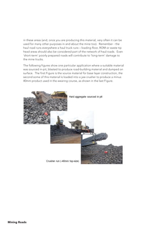
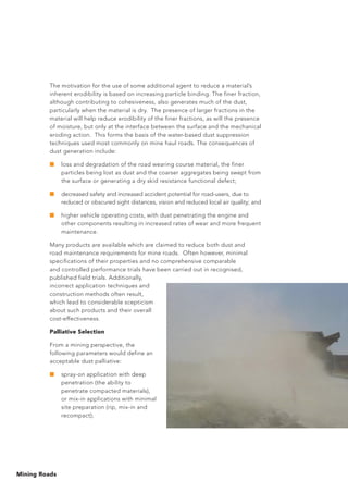
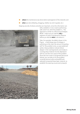
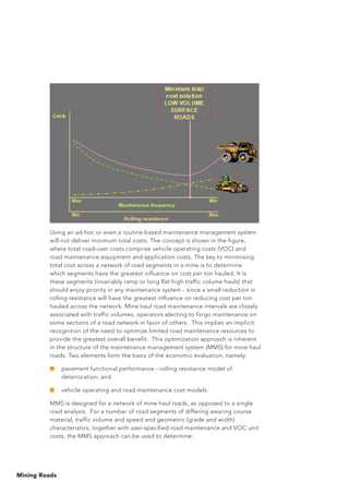
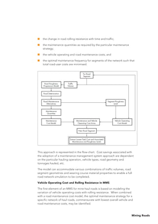
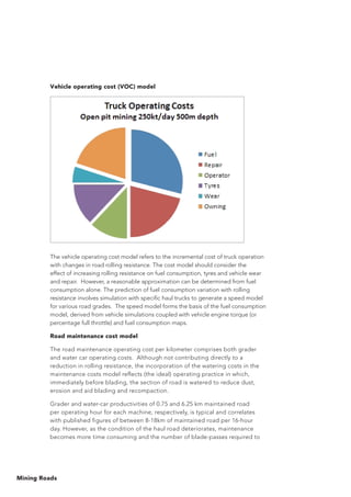
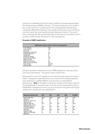
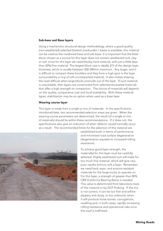
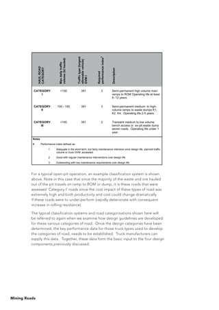
The document provides an overview of mine haul road design, construction, and maintenance. Some key points:
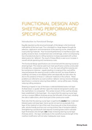
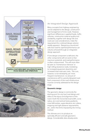
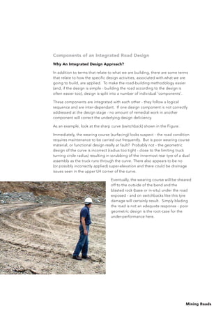
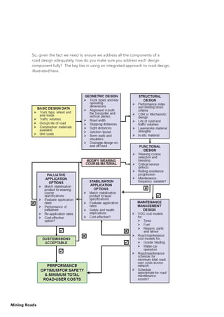
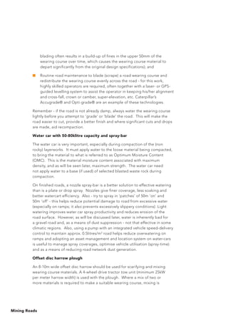
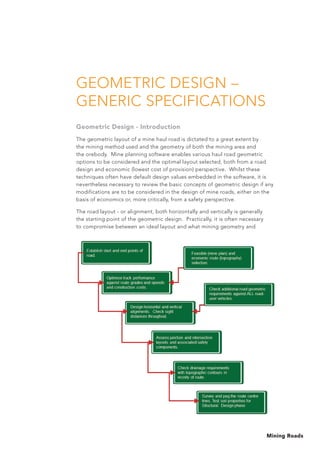
1) An integrated design approach is necessary to optimize haul road performance, considering geometric, structural, functional, and maintenance designs. Poor design of any one component can compromise overall road performance.
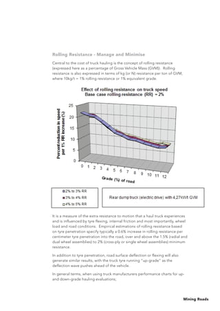
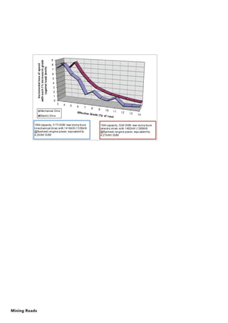
2) Rolling resistance is a major factor impacting haul truck productivity and costs. Even small reductions in rolling resistance through improved design can significantly increase truck speeds and productivity.
3) Different haul truck types have varying design requirements - articulated dump trucks can operate on poorer quality roads compared to rigid-body trucks, but all truck types benefit from a well-designed, constructed, and maintained haul road network.


![Mining Roads
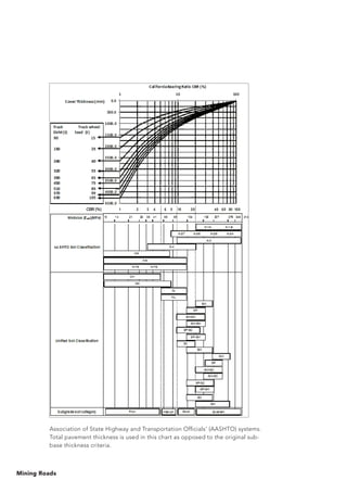
The following equation can alternatively be used to estimate the layer
thickness (ZCBR (m)) required for a material of California Bearing Ratio
(CBR %);
Where tw is the truck wheel load (metric tons), P is tyre pressure (kPa) and CBR
is the California Bearing Ratio of the material (%).
Originally, the wheel load was increased by 20% to replicate the effects of
the increased stresses generated by a rear dual-wheel axle which occur deeper
in a road layer - the concept of Equivalent Single Wheel Load (ESWL).
The following equation can be used to estimate the cover ZESWL (m) more
reliably as;
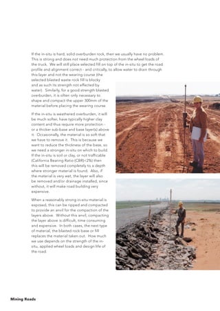
In using this technique, consider the ‘cover’ required for a 320t GVM haul
truck with a 55t wheel load. Using an ESWL approximation of 1.2xwheel load,
if the sub-grade CBR is 5%, the pavement thickness required is 1400mm.
If a sub-base of CBR=15% were placed above this, pavement cover is now
500mm so (1400-500) = 900mm layer thickness is required. Placing a base
of CBR=35% results in a layer thickness of 375mm, following which a 125mm
layer of CBR80% wearing course is applied. Ideally, a yet harder material is
required, but a wearing course of CBR80% is generally suitable and would for
design purposes be specified to 200mm depth from surface.
Using the equations presented previously for ZESWL gives 1790mm cover,
and layer thicknesses of 950mm, 430mm and (260+150)mm for each layer
respectively.
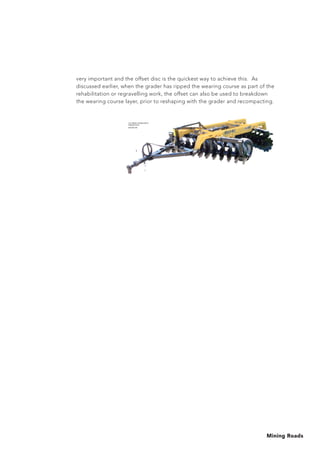
When multi-layered roads are considered in conjunction with a base layer of
selected blasted waste rock, a mechanistic approach is more appropriate.
When a selected waste rock layer is located under the wearing course, road
performance is significantly improved, primarily due to the load carrying
capacity of the waste rock layer which reduces the susceptibility of the soft
sub-grade to the effects of high axle loads. It also has the added advantage
of reduced construction costs (by virtue of reduced volumetric and compaction
requirements), compared with the CBR cover-curve design approach.
( )
[ ]
( )
+=
+ 4
w
Px100.415
P
CBR
50.0287tw
P
CBR
2x100.331e0.104
P
9.81t
CBRZ
1
w
ESWL
t
17.76CBR
0.086CBR0.184Z +++= CBRZ ( )
[ ]
( )
+=
+ 4
w
Px100.415
P
CBR
50.0287tw
P
CBR
2x100.331e0.104
P
9.81t
CBRZ
1
w
ESWL
t
17.76CBR
0.086CBR0.184Z +++= CBRZ](https://image.slidesharecdn.com/4miningroaddesignconstrucionmcm2011thompsonsa-190224084917/85/4-mining-road-designconstrucion-amp-m-cm-2011-thompson-sa-71-320.jpg)