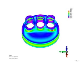
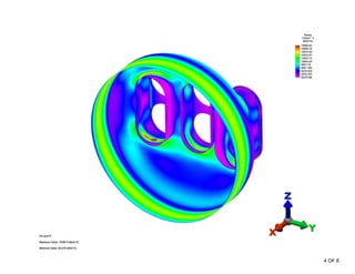
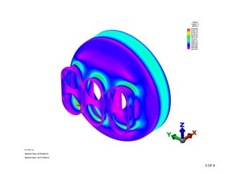
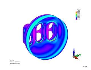
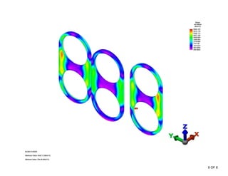
STRESS ANALYSIS                                                                REV A

HEAD WITH 3 FIRETUBES STRESS ANALYSIS TO ASME VIII-2


                               MaXfield Inc.
      Performed by: Zhanghai (John) Wang, ASME Certificated Member
                      Checked By: Daryl Bast, P. Eng.


Load Case and Materials

   In this revision calculation, the fire tubes are moved 2” upward. The vessel is
   analyzed under pressure 100 PSI with filled water. The vessel together with the
   fire tubes are made from SA 516-70. The thickness of the head welded with two
   fire tube necks is 1 1/2” with corrosion allowance 1/16”. The shell connected the
   head is 3/4” with corrosion allowance 1/16”. The fire tube neck nozzle is 1 1/4”
   with corrosion allowance 1/16”. The geometrical dimensions could be checked
   from the corresponding drawings.


Method of Calculation

A Finite Element Analysis is performed on the vessel together with fire tubes (but not
shown in output) according to the following:

   1. Components are modeled with plate elements except the nozzle blind flange
      modeled with brick element.
   2. Vessel is partially cut and included in the mesh.
   3. FEA model is constrained in cut section of the partial vessel and the end
      supports of the fire tubes

The FEA program employed is Algor FEMPRO Version 19.1-WIN. The geometry is
created in Superdraw.

Results

The following output is attached:

Stress Contours:

   (1) general primary membrane stress Pm and local primary membrane stress Pl
   (2) local primary membrane stress plus primary bending stress (Pl+Pb)
   (3) local primary membrane stress plus primary bending stress plus secondary
       stress (Pl+Pb+Q)
   (4) Nozzle blind flange stress in Von Mises


                                                                                         1 OF 8
STRESS ANALYSIS                                                                 REV A

Conclusions

For material SA 516-70, the ultimate strength is 70 ksi. Sm = 70/3.5= 20,000 psi

According to the simulated results, local primary membrane stress Pl is 19,996 psi;
general primary membrane stress on vessel is about 14,572psi; general primary
membrane stress on head < Sm; Pl + Pb + Q is 34,709 psi. After checking the
results, we find in all stress contour area of the vessel:

Pm < Sm = 20,000 PSI
Pl < 1.5 Sm = 30,000 PSI
Pl + Pb < 1.5 Sm = 30,000 PSI
Pl + Pb + Q < 3 Sm = 60,000 PSI

Therefore, the stresses on head and fire tubes satisfy the specific stress limits given
in the Appendix 4 of ASME VIII-2.


                                                                                          2 OF 8
3 OF 8
4 OF 8
5 OF 8
6 OF 8
7 OF 8
8 OF 8

3 Fire Tube Fea Calculation Viii Div2 Ra

  • 1.
    STRESS ANALYSIS REV A HEAD WITH 3 FIRETUBES STRESS ANALYSIS TO ASME VIII-2 MaXfield Inc. Performed by: Zhanghai (John) Wang, ASME Certificated Member Checked By: Daryl Bast, P. Eng. Load Case and Materials In this revision calculation, the fire tubes are moved 2” upward. The vessel is analyzed under pressure 100 PSI with filled water. The vessel together with the fire tubes are made from SA 516-70. The thickness of the head welded with two fire tube necks is 1 1/2” with corrosion allowance 1/16”. The shell connected the head is 3/4” with corrosion allowance 1/16”. The fire tube neck nozzle is 1 1/4” with corrosion allowance 1/16”. The geometrical dimensions could be checked from the corresponding drawings. Method of Calculation A Finite Element Analysis is performed on the vessel together with fire tubes (but not shown in output) according to the following: 1. Components are modeled with plate elements except the nozzle blind flange modeled with brick element. 2. Vessel is partially cut and included in the mesh. 3. FEA model is constrained in cut section of the partial vessel and the end supports of the fire tubes The FEA program employed is Algor FEMPRO Version 19.1-WIN. The geometry is created in Superdraw. Results The following output is attached: Stress Contours: (1) general primary membrane stress Pm and local primary membrane stress Pl (2) local primary membrane stress plus primary bending stress (Pl+Pb) (3) local primary membrane stress plus primary bending stress plus secondary stress (Pl+Pb+Q) (4) Nozzle blind flange stress in Von Mises 1 OF 8
  • 2.
    STRESS ANALYSIS REV A Conclusions For material SA 516-70, the ultimate strength is 70 ksi. Sm = 70/3.5= 20,000 psi According to the simulated results, local primary membrane stress Pl is 19,996 psi; general primary membrane stress on vessel is about 14,572psi; general primary membrane stress on head < Sm; Pl + Pb + Q is 34,709 psi. After checking the results, we find in all stress contour area of the vessel: Pm < Sm = 20,000 PSI Pl < 1.5 Sm = 30,000 PSI Pl + Pb < 1.5 Sm = 30,000 PSI Pl + Pb + Q < 3 Sm = 60,000 PSI Therefore, the stresses on head and fire tubes satisfy the specific stress limits given in the Appendix 4 of ASME VIII-2. 2 OF 8
  • 3.
  • 4.
  • 5.
  • 6.
  • 7.
  • 8.