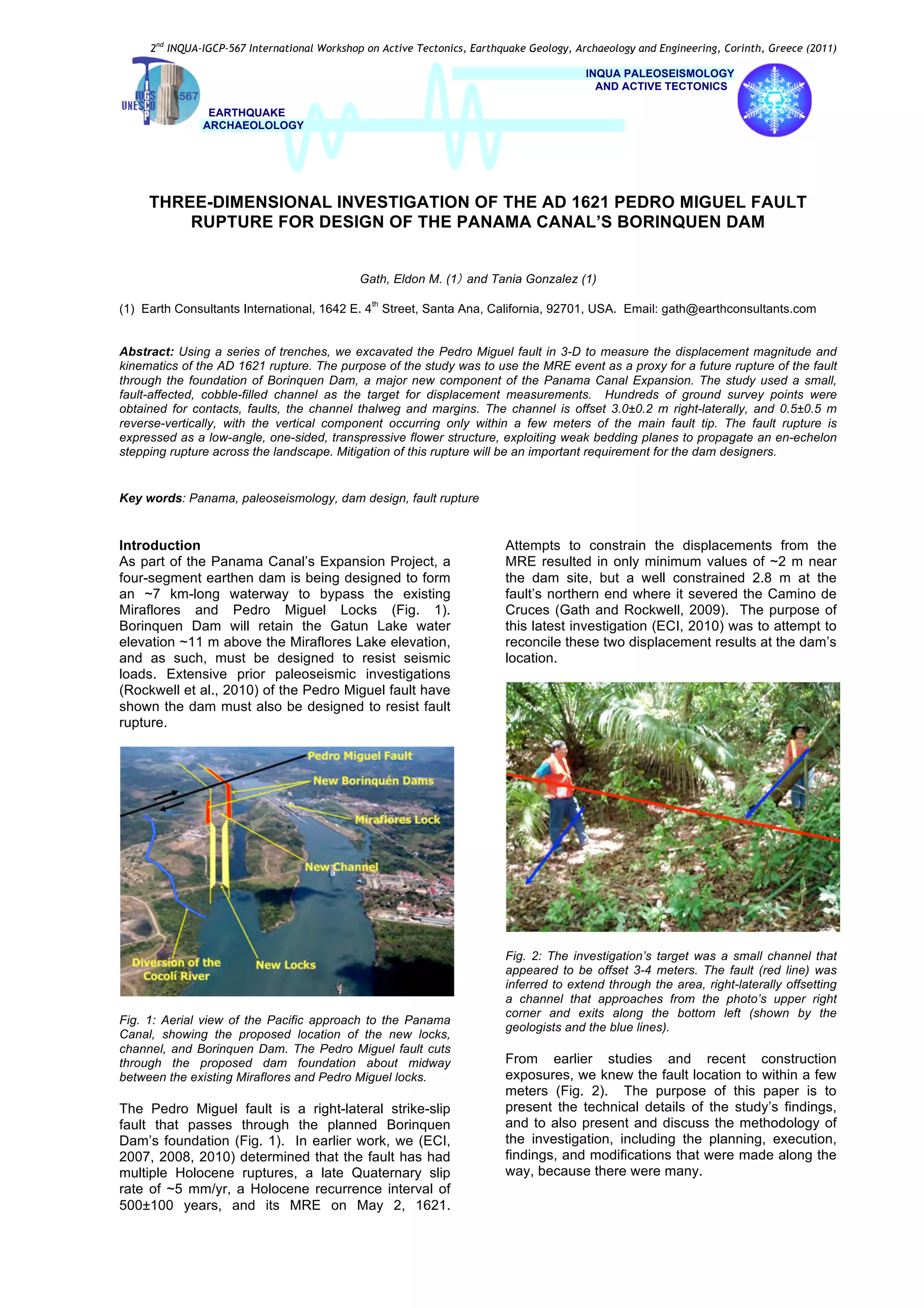
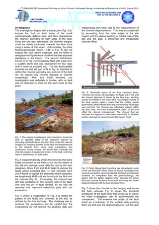
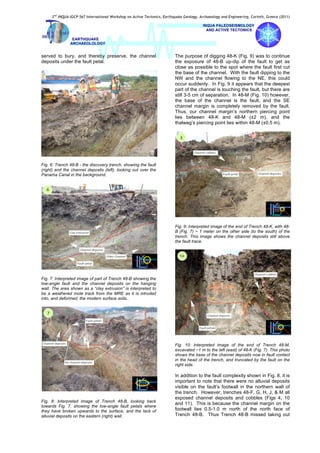
2nd
INQUA-IGCP-567 International Workshop on Active Tectonics, Earthquake Geology, Archaeology and Engineering, Corinth, Greece (2011)
INQUA PALEOSEISMOLOGY
AND ACTIVE TECTONICS
EARTHQUAKE
ARCHAEOLOLOGY
THREE-DIMENSIONAL INVESTIGATION OF THE AD 1621 PEDRO MIGUEL FAULT
RUPTURE FOR DESIGN OF THE PANAMA CANAL’S BORINQUEN DAM
Gath, Eldon M. (1) and Tania Gonzalez (1)
(1) Earth Consultants International, 1642 E. 4
th
Street, Santa Ana, California, 92701, USA. Email: gath@earthconsultants.com
Abstract: Using a series of trenches, we excavated the Pedro Miguel fault in 3-D to measure the displacement magnitude and
kinematics of the AD 1621 rupture. The purpose of the study was to use the MRE event as a proxy for a future rupture of the fault
through the foundation of Borinquen Dam, a major new component of the Panama Canal Expansion. The study used a small,
fault-affected, cobble-filled channel as the target for displacement measurements. Hundreds of ground survey points were
obtained for contacts, faults, the channel thalweg and margins. The channel is offset 3.0±0.2 m right-laterally, and 0.5±0.5 m
reverse-vertically, with the vertical component occurring only within a few meters of the main fault tip. The fault rupture is
expressed as a low-angle, one-sided, transpressive flower structure, exploiting weak bedding planes to propagate an en-echelon
stepping rupture across the landscape. Mitigation of this rupture will be an important requirement for the dam designers.
Key words: Panama, paleoseismology, dam design, fault rupture
Introduction
As part of the Panama Canal’s Expansion Project, a
four-segment earthen dam is being designed to form
an ~7 km-long waterway to bypass the existing
Miraflores and Pedro Miguel Locks (Fig. 1).
Borinquen Dam will retain the Gatun Lake water
elevation ~11 m above the Miraflores Lake elevation,
and as such, must be designed to resist seismic
loads. Extensive prior paleoseismic investigations
(Rockwell et al., 2010) of the Pedro Miguel fault have
shown the dam must also be designed to resist fault
rupture.
Fig. 1: Aerial view of the Pacific approach to the Panama
Canal, showing the proposed location of the new locks,
channel, and Borinquen Dam. The Pedro Miguel fault cuts
through the proposed dam foundation about midway
between the existing Miraflores and Pedro Miguel locks.
The Pedro Miguel fault is a right-lateral strike-slip
fault that passes through the planned Borinquen
Dam’s foundation (Fig. 1). In earlier work, we (ECI,
2007, 2008, 2010) determined that the fault has had
multiple Holocene ruptures, a late Quaternary slip
rate of ~5 mm/yr, a Holocene recurrence interval of
500±100 years, and its MRE on May 2, 1621.
Attempts to constrain the displacements from the
MRE resulted in only minimum values of ~2 m near
the dam site, but a well constrained 2.8 m at the
fault’s northern end where it severed the Camino de
Cruces (Gath and Rockwell, 2009). The purpose of
this latest investigation (ECI, 2010) was to attempt to
reconcile these two displacement results at the dam’s
location.
Fig. 2: The investigation’s target was a small channel that
appeared to be offset 3-4 meters. The fault (red line) was
inferred to extend through the area, right-laterally offsetting
a channel that approaches from the photo’s upper right
corner and exits along the bottom left (shown by the
geologists and the blue lines).
From earlier studies and recent construction
exposures, we knew the fault location to within a few
meters (Fig. 2). The purpose of this paper is to
present the technical details of the study’s findings,
and to also present and discuss the methodology of
the investigation, including the planning, execution,
findings, and modifications that were made along the
way, because there were many.
2nd
INQUA-IGCP-567 International Workshop on Active Tectonics, Earthquake Geology, Archaeology and Engineering, Corinth, Greece (2011)
INQUA PALEOSEISMOLOGY
AND ACTIVE TECTONICS
EARTHQUAKE
ARCHAEOLOLOGY
Investigation
The investigation began with a simple plan (Fig. 3) to
expose the fault on both sides of the small
geomorphically defined area, and then characterize
the channel geometry on both sides of the fault.
Once the site was delineated, the channel margins
could be slowly excavated towards the fault trace
using a series of thin slices. Unfortunately, the initial
fault-perpendicular trench (T-48 in Fig. 4) did not
expose the fault where expected, and we failed to
recognize the significance of a fault that was exposed
elsewhere in the trench. The second fault-locator
trench (C in Fig. 4) immediately filled with water from
a sudden storm and was abandoned for four days
until it could be pumped out. The two fault-parallel
trenches (A and left part of B in Fig. 4) intended to
define the channel geometry into and out of the fault
did not expose any channel deposits or channel
morphology. After four initial trenches, our
investigation was definitely in trouble, with no fault
and no channels to show for the work done to that
point.
Fig. 3: The original investigation plan intended to locate the
fault on opposite sides of the displaced channel by
trenching perpendicular to the fault, then locate the channel
margins by trenching parallel to the fault and perpendicular
to the channel form. Using hand excavations and
continuous survey control, we would then excavate the
channel margins progressively closer to the fault, until they
were in fault-contact on both sides.
Fig. 4 diagrammatically shows the trenches that were
finally excavated as we tried to sort out the details of
the site and salvage some data for use by the dam
designers. Once T-48 and 48-C failed to expose the
faults where expected (Fig. 4), and trenches 48-A
and B failed to expose the channels where expected,
we lengthened 48-B until we found both the fault and
the channel (Fig. 6). Fortunately, the channel was
still fully contained on the hanging wall of the fault,
and was not yet in fault contact, so we had not
removed that important interaction point with our
excavation.
Fig. 5 shows a modification of Fig. 3 to reflect the
pattern of the faults and channels at the site, as
defined by the final trenches. The challenge was to
continue the excavations but be careful that the
excavations did not remove the geologic data and
relationships that were vital to the measurement of
the channel displacements. This was accomplished
by excavating from the outer edges of the site
inward, and by always keeping a mental map of the
site and the goal, a preserved and measurable
channel offset.
Fig. 4: Schematic layout of our final trenching study.
Trenches are shown as rectangles, the faults are in red, and
the channel structure is shown by the blue lines, trending
across the middle of the study area. The complex nature of
the fault rupture pattern meant that the initially simple
geomorphic offset inferred from the pre-trenching landscape
was incorrect. The channel was effectively trapped within
the fault zone, and each transpressive “petal” of the fault
offset the channel progressively. The channel that we
trenched first appears to have been man-made, to facilitate
surface drainage to a culvert under Borinquen Road.
Fig. 5: Pedro Miguel fault trenching site immediately south
of the old Borinquén Road (base of photo), following brush
removal, but before trenching started. The fault and channel
locations, as interpreted from the geomorphology, are
shown with the lighter, dashed lines, whereas the actual
fault and channel locations found after trenching are shown
diagrammatically with the bold and solid lines.
Fig. 7 shows the channel on the hanging wall above
the fault, whereas Fig. 8 shows the structural
complexity of the fault zone that forced us to evolve
the initial investigation plan to accommodate the
unexpected. The extreme low angle of the fault
acted as a bulldozer of the surface soils pushing
them out and over the channel alluvium, but this also
2nd
INQUA-IGCP-567 International Workshop on Active Tectonics, Earthquake Geology, Archaeology and Engineering, Corinth, Greece (2011)
INQUA PALEOSEISMOLOGY
AND ACTIVE TECTONICS
EARTHQUAKE
ARCHAEOLOLOGY
served to bury, and thereby preserve, the channel
deposits under the fault petal.
Fig. 6: Trench 48-B - the discovery trench, showing the fault
(right) and the channel deposits (left), looking out over the
Panama Canal in the background.
Fig. 7: Interpreted image of part of Trench 48-B showing the
low-angle fault and the channel deposits on the hanging
wall. The area shown as a “clay extrusion” is interpreted to
be a weathered mole track from the MRE as it is intruded
into, and deformed, the modern surface soils..
Fig. 8: Interpreted image of Trench 48-B, looking back
towards Fig. 7, showing the low-angle fault petals where
they have broken upwards to the surface, and the lack of
alluvial deposits on the eastern (right) wall.
The purpose of digging 48-K (Fig. 9) was to continue
the exposure of 48-B up-dip of the fault to get as
close as possible to the spot where the fault first cut
the base of the channel. With the fault dipping to the
NW and the channel flowing to the NE, this could
occur suddenly. In Fig. 9 it appears that the deepest
part of the channel is touching the fault, but there are
still 3-5 cm of separation. In 48-M (Fig. 10) however,
the base of the channel is the fault, and the SE
channel margin is completely removed by the fault.
Thus, our channel margin’s northern piercing point
lies between 48-K and 48-M (±2 m), and the
thalweg’s piercing point lies within 48-M (±0.5 m).
Fig. 9: Interpreted image of the end of Trench 48-K, with 48-
B (Fig. 7) ~ 1 meter on the other side (to the south) of the
trench. This image shows the channel deposits still above
the fault trace.
Fig. 10: Interpreted image of the end of Trench 48-M,
excavated ~1 m to the left (east) of 48-K (Fig. 7). This photo
shows the base of the channel deposits now in fault contact
in the head of the trench, and truncated by the fault on the
right side.
In addition to the fault complexity shown in Fig. 8, it is
important to note that there were no alluvial deposits
visible on the fault’s footwall in the northern wall of
the trench. However, trenches 48-F, G, H, J, & M all
exposed channel deposits and cobbles (Figs 4, 10
and 11). This is because the channel margin on the
footwall lies 0.5-1.0 m north of the north face of
Trench 48-B. Thus Trench 48-B missed taking out
2nd
INQUA-IGCP-567 International Workshop on Active Tectonics, Earthquake Geology, Archaeology and Engineering, Corinth, Greece (2011)
INQUA PALEOSEISMOLOGY
AND ACTIVE TECTONICS
EARTHQUAKE
ARCHAEOLOLOGY
the southern margin of our target channel by less
than 1 m. With the southern margin so tightly
constrained, the most accurate offset measurements
came from that side.
Fig. 11: Interpreted image of Trench 48-H, with 48-B (Fig. 8)
exposed through the window at the end of the trench. This
image shows the limits of the channel deposits on the
footwall side of the fault, and shows a secondary fault petal
on the right wall vertically truncating the cobble deposits
within the excavated width of the trench.
Fig. 12: Geologically interpreted map of the channel offsets
based on hundreds of survey points collected. The yellow
area reflects the full margins of the sandy channel deposits
whereas the blue area defines the cobble-filled channel
thalweg. The northern margin of the channel is more poorly
constrained (±2 m), while the southern margin and thalweg
margins are constrained to less than ±1 m. The right-lateral
offset across the fault is measured at 3.0±0.2 m. A 0.5 m
vertical offset occurred at the tip of the main fault petal,
resulting in the upward bowing and erosional removal of the
channel thalweg, but this uplift is localized to only a few
meters from the fault tip and is not present away from the
fault. Farther east, the fault tip over-rides and protects the
alluvial channel deposits.
Conclusions
Although the study was much more complicated than
initially planned, we were successful in locating the
fault, in exposing a young channel that was offset
across the fault, and in measuring the offset of that
channel by the most recent earthquake. Using 15
trenches and hundreds of surveyed data points, we
were able to constrain the MRE rupture to 3.0±0.2 m
of right-lateral displacement, and 0.5±0.5 m of
localized reverse-slip uplift at the surface tip of the
fault. Because the fault is expressed through the
dam as an en-echelon stepping, transpressional
flower structure that exploits the weak bedding
planes of the near-surface strata, it will be a difficult
fault to mitigate in the design of the Borinquen Dam
(Fig. 13).
Fig. 13: Map of the Pedro Miguel and Miraflores faults
through the Borinquen Dam area (hachured). Areas where
we have conducted paleoseismic trenching are shown with
the green squares; the green square directly over the dam
location is the location of this study.
Acknowledgements
Thanks to Kay St. Peters and Barrett Salisbury for excellent
field assistance and data mapping. Appreciation is due to
the Autoridad del Canal de Panama for permission to
conduct this study and to Ms. Pastora Franceschi for
arranging all the details.
References
Earth Consultants International (ECI), 2007, Paleoseismic
Trenching of the Pedro Miguel Fault in Cocolí, Located
Immediately Southwest of the Panamá Canal, Panamá;
consulting report for the Autoridad del Canal de Panamá
(ACP), Project No. 2614.02.
ECI, 2008, Quantitative Characterization of the Pedro
Miguel Fault, Determination of Recency of Activity on the
Miraflores Fault, and Detailed Mapping of the Active
Faults Through the Proposed Borinquén Dam Location;
consulting report for the ACP, Project No. 2708.05.
ECI, 2010, Additional Trenching of the Pedro Miguel and
Miraflores faults in Cocoli, immediately southwest of the
Panamá Canal; consulting report for the ACP, Project No.
3012.
Gath, E.M. and Rockwell, T.K., 2009, Coseismic offset of
the Camino de Cruces confirms the Pedro Miguel fault as
the cause of the AD 1621 Panamá Viejo earthquake; in
Pérez-Lopez, R. and others (eds), Archeoseismology and
Palaeoseismology:: 1
st
INQUA-IGCP-567 Int. Workshop
on Earthquake Archaeology and Palaeoseismology,
Baelo Claudia, Spain, p. 32-34.
Rockwell, T. and others, 2010, Neotectonics and
paleoseismology of the Limón and Pedro Miguel faults in
Panamá: Earthquake Hazard to the Panamá Canal: B. of
the Seis. Soc. America, v. 100, p. 3097-3129.

3-D Borinquen Dam INQUA Paper-lr

  • 1.
    2nd INQUA-IGCP-567 International Workshopon Active Tectonics, Earthquake Geology, Archaeology and Engineering, Corinth, Greece (2011) INQUA PALEOSEISMOLOGY AND ACTIVE TECTONICS EARTHQUAKE ARCHAEOLOLOGY THREE-DIMENSIONAL INVESTIGATION OF THE AD 1621 PEDRO MIGUEL FAULT RUPTURE FOR DESIGN OF THE PANAMA CANAL’S BORINQUEN DAM Gath, Eldon M. (1) and Tania Gonzalez (1) (1) Earth Consultants International, 1642 E. 4 th Street, Santa Ana, California, 92701, USA. Email: gath@earthconsultants.com Abstract: Using a series of trenches, we excavated the Pedro Miguel fault in 3-D to measure the displacement magnitude and kinematics of the AD 1621 rupture. The purpose of the study was to use the MRE event as a proxy for a future rupture of the fault through the foundation of Borinquen Dam, a major new component of the Panama Canal Expansion. The study used a small, fault-affected, cobble-filled channel as the target for displacement measurements. Hundreds of ground survey points were obtained for contacts, faults, the channel thalweg and margins. The channel is offset 3.0±0.2 m right-laterally, and 0.5±0.5 m reverse-vertically, with the vertical component occurring only within a few meters of the main fault tip. The fault rupture is expressed as a low-angle, one-sided, transpressive flower structure, exploiting weak bedding planes to propagate an en-echelon stepping rupture across the landscape. Mitigation of this rupture will be an important requirement for the dam designers. Key words: Panama, paleoseismology, dam design, fault rupture Introduction As part of the Panama Canal’s Expansion Project, a four-segment earthen dam is being designed to form an ~7 km-long waterway to bypass the existing Miraflores and Pedro Miguel Locks (Fig. 1). Borinquen Dam will retain the Gatun Lake water elevation ~11 m above the Miraflores Lake elevation, and as such, must be designed to resist seismic loads. Extensive prior paleoseismic investigations (Rockwell et al., 2010) of the Pedro Miguel fault have shown the dam must also be designed to resist fault rupture. Fig. 1: Aerial view of the Pacific approach to the Panama Canal, showing the proposed location of the new locks, channel, and Borinquen Dam. The Pedro Miguel fault cuts through the proposed dam foundation about midway between the existing Miraflores and Pedro Miguel locks. The Pedro Miguel fault is a right-lateral strike-slip fault that passes through the planned Borinquen Dam’s foundation (Fig. 1). In earlier work, we (ECI, 2007, 2008, 2010) determined that the fault has had multiple Holocene ruptures, a late Quaternary slip rate of ~5 mm/yr, a Holocene recurrence interval of 500±100 years, and its MRE on May 2, 1621. Attempts to constrain the displacements from the MRE resulted in only minimum values of ~2 m near the dam site, but a well constrained 2.8 m at the fault’s northern end where it severed the Camino de Cruces (Gath and Rockwell, 2009). The purpose of this latest investigation (ECI, 2010) was to attempt to reconcile these two displacement results at the dam’s location. Fig. 2: The investigation’s target was a small channel that appeared to be offset 3-4 meters. The fault (red line) was inferred to extend through the area, right-laterally offsetting a channel that approaches from the photo’s upper right corner and exits along the bottom left (shown by the geologists and the blue lines). From earlier studies and recent construction exposures, we knew the fault location to within a few meters (Fig. 2). The purpose of this paper is to present the technical details of the study’s findings, and to also present and discuss the methodology of the investigation, including the planning, execution, findings, and modifications that were made along the way, because there were many.
  • 2.
    2nd INQUA-IGCP-567 International Workshopon Active Tectonics, Earthquake Geology, Archaeology and Engineering, Corinth, Greece (2011) INQUA PALEOSEISMOLOGY AND ACTIVE TECTONICS EARTHQUAKE ARCHAEOLOLOGY Investigation The investigation began with a simple plan (Fig. 3) to expose the fault on both sides of the small geomorphically defined area, and then characterize the channel geometry on both sides of the fault. Once the site was delineated, the channel margins could be slowly excavated towards the fault trace using a series of thin slices. Unfortunately, the initial fault-perpendicular trench (T-48 in Fig. 4) did not expose the fault where expected, and we failed to recognize the significance of a fault that was exposed elsewhere in the trench. The second fault-locator trench (C in Fig. 4) immediately filled with water from a sudden storm and was abandoned for four days until it could be pumped out. The two fault-parallel trenches (A and left part of B in Fig. 4) intended to define the channel geometry into and out of the fault did not expose any channel deposits or channel morphology. After four initial trenches, our investigation was definitely in trouble, with no fault and no channels to show for the work done to that point. Fig. 3: The original investigation plan intended to locate the fault on opposite sides of the displaced channel by trenching perpendicular to the fault, then locate the channel margins by trenching parallel to the fault and perpendicular to the channel form. Using hand excavations and continuous survey control, we would then excavate the channel margins progressively closer to the fault, until they were in fault-contact on both sides. Fig. 4 diagrammatically shows the trenches that were finally excavated as we tried to sort out the details of the site and salvage some data for use by the dam designers. Once T-48 and 48-C failed to expose the faults where expected (Fig. 4), and trenches 48-A and B failed to expose the channels where expected, we lengthened 48-B until we found both the fault and the channel (Fig. 6). Fortunately, the channel was still fully contained on the hanging wall of the fault, and was not yet in fault contact, so we had not removed that important interaction point with our excavation. Fig. 5 shows a modification of Fig. 3 to reflect the pattern of the faults and channels at the site, as defined by the final trenches. The challenge was to continue the excavations but be careful that the excavations did not remove the geologic data and relationships that were vital to the measurement of the channel displacements. This was accomplished by excavating from the outer edges of the site inward, and by always keeping a mental map of the site and the goal, a preserved and measurable channel offset. Fig. 4: Schematic layout of our final trenching study. Trenches are shown as rectangles, the faults are in red, and the channel structure is shown by the blue lines, trending across the middle of the study area. The complex nature of the fault rupture pattern meant that the initially simple geomorphic offset inferred from the pre-trenching landscape was incorrect. The channel was effectively trapped within the fault zone, and each transpressive “petal” of the fault offset the channel progressively. The channel that we trenched first appears to have been man-made, to facilitate surface drainage to a culvert under Borinquen Road. Fig. 5: Pedro Miguel fault trenching site immediately south of the old Borinquén Road (base of photo), following brush removal, but before trenching started. The fault and channel locations, as interpreted from the geomorphology, are shown with the lighter, dashed lines, whereas the actual fault and channel locations found after trenching are shown diagrammatically with the bold and solid lines. Fig. 7 shows the channel on the hanging wall above the fault, whereas Fig. 8 shows the structural complexity of the fault zone that forced us to evolve the initial investigation plan to accommodate the unexpected. The extreme low angle of the fault acted as a bulldozer of the surface soils pushing them out and over the channel alluvium, but this also
  • 3.
    2nd INQUA-IGCP-567 International Workshopon Active Tectonics, Earthquake Geology, Archaeology and Engineering, Corinth, Greece (2011) INQUA PALEOSEISMOLOGY AND ACTIVE TECTONICS EARTHQUAKE ARCHAEOLOLOGY served to bury, and thereby preserve, the channel deposits under the fault petal. Fig. 6: Trench 48-B - the discovery trench, showing the fault (right) and the channel deposits (left), looking out over the Panama Canal in the background. Fig. 7: Interpreted image of part of Trench 48-B showing the low-angle fault and the channel deposits on the hanging wall. The area shown as a “clay extrusion” is interpreted to be a weathered mole track from the MRE as it is intruded into, and deformed, the modern surface soils.. Fig. 8: Interpreted image of Trench 48-B, looking back towards Fig. 7, showing the low-angle fault petals where they have broken upwards to the surface, and the lack of alluvial deposits on the eastern (right) wall. The purpose of digging 48-K (Fig. 9) was to continue the exposure of 48-B up-dip of the fault to get as close as possible to the spot where the fault first cut the base of the channel. With the fault dipping to the NW and the channel flowing to the NE, this could occur suddenly. In Fig. 9 it appears that the deepest part of the channel is touching the fault, but there are still 3-5 cm of separation. In 48-M (Fig. 10) however, the base of the channel is the fault, and the SE channel margin is completely removed by the fault. Thus, our channel margin’s northern piercing point lies between 48-K and 48-M (±2 m), and the thalweg’s piercing point lies within 48-M (±0.5 m). Fig. 9: Interpreted image of the end of Trench 48-K, with 48- B (Fig. 7) ~ 1 meter on the other side (to the south) of the trench. This image shows the channel deposits still above the fault trace. Fig. 10: Interpreted image of the end of Trench 48-M, excavated ~1 m to the left (east) of 48-K (Fig. 7). This photo shows the base of the channel deposits now in fault contact in the head of the trench, and truncated by the fault on the right side. In addition to the fault complexity shown in Fig. 8, it is important to note that there were no alluvial deposits visible on the fault’s footwall in the northern wall of the trench. However, trenches 48-F, G, H, J, & M all exposed channel deposits and cobbles (Figs 4, 10 and 11). This is because the channel margin on the footwall lies 0.5-1.0 m north of the north face of Trench 48-B. Thus Trench 48-B missed taking out
  • 4.
    2nd INQUA-IGCP-567 International Workshopon Active Tectonics, Earthquake Geology, Archaeology and Engineering, Corinth, Greece (2011) INQUA PALEOSEISMOLOGY AND ACTIVE TECTONICS EARTHQUAKE ARCHAEOLOLOGY the southern margin of our target channel by less than 1 m. With the southern margin so tightly constrained, the most accurate offset measurements came from that side. Fig. 11: Interpreted image of Trench 48-H, with 48-B (Fig. 8) exposed through the window at the end of the trench. This image shows the limits of the channel deposits on the footwall side of the fault, and shows a secondary fault petal on the right wall vertically truncating the cobble deposits within the excavated width of the trench. Fig. 12: Geologically interpreted map of the channel offsets based on hundreds of survey points collected. The yellow area reflects the full margins of the sandy channel deposits whereas the blue area defines the cobble-filled channel thalweg. The northern margin of the channel is more poorly constrained (±2 m), while the southern margin and thalweg margins are constrained to less than ±1 m. The right-lateral offset across the fault is measured at 3.0±0.2 m. A 0.5 m vertical offset occurred at the tip of the main fault petal, resulting in the upward bowing and erosional removal of the channel thalweg, but this uplift is localized to only a few meters from the fault tip and is not present away from the fault. Farther east, the fault tip over-rides and protects the alluvial channel deposits. Conclusions Although the study was much more complicated than initially planned, we were successful in locating the fault, in exposing a young channel that was offset across the fault, and in measuring the offset of that channel by the most recent earthquake. Using 15 trenches and hundreds of surveyed data points, we were able to constrain the MRE rupture to 3.0±0.2 m of right-lateral displacement, and 0.5±0.5 m of localized reverse-slip uplift at the surface tip of the fault. Because the fault is expressed through the dam as an en-echelon stepping, transpressional flower structure that exploits the weak bedding planes of the near-surface strata, it will be a difficult fault to mitigate in the design of the Borinquen Dam (Fig. 13). Fig. 13: Map of the Pedro Miguel and Miraflores faults through the Borinquen Dam area (hachured). Areas where we have conducted paleoseismic trenching are shown with the green squares; the green square directly over the dam location is the location of this study. Acknowledgements Thanks to Kay St. Peters and Barrett Salisbury for excellent field assistance and data mapping. Appreciation is due to the Autoridad del Canal de Panama for permission to conduct this study and to Ms. Pastora Franceschi for arranging all the details. References Earth Consultants International (ECI), 2007, Paleoseismic Trenching of the Pedro Miguel Fault in Cocolí, Located Immediately Southwest of the Panamá Canal, Panamá; consulting report for the Autoridad del Canal de Panamá (ACP), Project No. 2614.02. ECI, 2008, Quantitative Characterization of the Pedro Miguel Fault, Determination of Recency of Activity on the Miraflores Fault, and Detailed Mapping of the Active Faults Through the Proposed Borinquén Dam Location; consulting report for the ACP, Project No. 2708.05. ECI, 2010, Additional Trenching of the Pedro Miguel and Miraflores faults in Cocoli, immediately southwest of the Panamá Canal; consulting report for the ACP, Project No. 3012. Gath, E.M. and Rockwell, T.K., 2009, Coseismic offset of the Camino de Cruces confirms the Pedro Miguel fault as the cause of the AD 1621 Panamá Viejo earthquake; in Pérez-Lopez, R. and others (eds), Archeoseismology and Palaeoseismology:: 1 st INQUA-IGCP-567 Int. Workshop on Earthquake Archaeology and Palaeoseismology, Baelo Claudia, Spain, p. 32-34. Rockwell, T. and others, 2010, Neotectonics and paleoseismology of the Limón and Pedro Miguel faults in Panamá: Earthquake Hazard to the Panamá Canal: B. of the Seis. Soc. America, v. 100, p. 3097-3129.