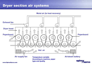
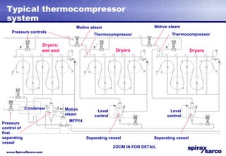
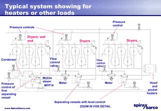
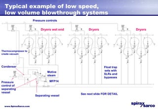
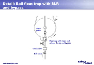
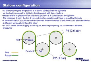
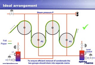
Steam systems  Part 2
The dryer section Moist air (to heat recovery) Exhaust fan Hot  air Paperboard Paperboard Air/steam battery Air supply fan Dryer hood
Dryer section air systems Moist air (to heat recovery) Exhaust fan Hot  air Paperboard Paperboard Air/steam battery Air supply fan Dryer hood Temperature variable According to machine, paper type and quality
Why pressure builds up in the cylinders / pocket ventilation FELT ROLL CYLINDER DRYER POCKET  VENTILATION DUCT FELT
Cascade system: principle High pressure steam applications PRV Medium pressure steam applications Low pressure steam applications High pressure steam Medium pressure steam Low pressure steam Medium pressure flash steam Low  pressure flash steam Separating vessel Separating vessel PRV Live steam Flash steam Condensate Condensate and blowthrough steam
Typical blowthrough cascade system (paper) Dryers: wet end Dryers Dryers Condenser Separating vessel Motive steam Pressure control for first separating vessel Pressure control Flow control valve Meter Level control MFP14 ZOOM IN FOR DETAIL
Typical thermocompressor system Thermocompressor Dryers: wet end Dryers Dryers Separating vessel Motive steam Pressure control of first separating vessel Level control MFP14 Condenser Pressure controls Motive steam Thermocompressor Motive steam ZOOM IN FOR DETAIL Separating vessel Level control
Typical system showing for heaters or other loads Dryers: wet end Dryers Dryers Separating vessels with level control Motive steam MFP14 Condenser Pressure controls Meter Flow control valve Hood and pocket heaters Pressure control ZOOM IN FOR DETAIL Meter Flow control valve Pressure control of first separating vessel
Typical example of low speed, low volume blowthrough systems Condenser Separating vessel Motive steam MFP14 Float trap sets with SLRs and bypasses Pressure controls Dryers Dryers Dryers wet end See next slide FOR DETAIL Thermocompressor to create vacuum Pressure control of separating vessel
Detail: Ball float trap with SLR and bypass Float trap with steam lock release device and bypass Sight glass Check valve Ball valve
Slalom configuration At the upper dryers the product is in direct contact with the cylinders At the bottom group the felt is in direct contact with the cylinders Heat transfer is greater when the moist product is in contact with the cylinder The pressure drop in the top dryers is therefore greater and there is less blowthrough A similar situation occurs on board machines where one side of the product must be heated to a different temperature than the other In such cases steam supply to the top vs. bottom group may be controlled at different pressures Product Felt Felt Product P1 (0.5 bar) P2 (1 bar) Felt Paper
Incorrect arrangement: effect on condensate drainage P1 P1 P2 P2 Level control P2 Steam pressure P    The slalom configuration so commonly used can cause waterlogging DPT Felt Paper
Ideal arrangement P1 P1 P2 P2 LC P1 P2 Steam pressure P    To ensure efficient removal of condensate the two groups should drain into separate mains Level control Felt Paper
Yankee dryers Cylinder steam supply and drainage
Yankee dryer View A To flash / separating vessel Steam Condensate pick-up Rotating cylinder
Yankee dryer  ‘View A’ Condensate pick-up
The need for steam lock release Condensate is held back behind the steam The steam ’ bubble’ inside the syphon pipe and the centre pipe prevents the condensate from escaping Steam filled cylinder
Yankee cylinder with thermocompressor Central condensate collection point Condensate to boiler feed tank Flash steam Air vent Steam and condensate from the cylinder Motive steam Separating vessel Condensate tank PIC PG PIC LC 3 m/s

3b Paper Machine Steam Systems Part2

  • 1.
  • 2.
    The dryer sectionMoist air (to heat recovery) Exhaust fan Hot air Paperboard Paperboard Air/steam battery Air supply fan Dryer hood
  • 3.
    Dryer section airsystems Moist air (to heat recovery) Exhaust fan Hot air Paperboard Paperboard Air/steam battery Air supply fan Dryer hood Temperature variable According to machine, paper type and quality
  • 4.
    Why pressure buildsup in the cylinders / pocket ventilation FELT ROLL CYLINDER DRYER POCKET VENTILATION DUCT FELT
  • 5.
    Cascade system: principleHigh pressure steam applications PRV Medium pressure steam applications Low pressure steam applications High pressure steam Medium pressure steam Low pressure steam Medium pressure flash steam Low pressure flash steam Separating vessel Separating vessel PRV Live steam Flash steam Condensate Condensate and blowthrough steam
  • 6.
    Typical blowthrough cascadesystem (paper) Dryers: wet end Dryers Dryers Condenser Separating vessel Motive steam Pressure control for first separating vessel Pressure control Flow control valve Meter Level control MFP14 ZOOM IN FOR DETAIL
  • 7.
    Typical thermocompressor systemThermocompressor Dryers: wet end Dryers Dryers Separating vessel Motive steam Pressure control of first separating vessel Level control MFP14 Condenser Pressure controls Motive steam Thermocompressor Motive steam ZOOM IN FOR DETAIL Separating vessel Level control
  • 8.
    Typical system showingfor heaters or other loads Dryers: wet end Dryers Dryers Separating vessels with level control Motive steam MFP14 Condenser Pressure controls Meter Flow control valve Hood and pocket heaters Pressure control ZOOM IN FOR DETAIL Meter Flow control valve Pressure control of first separating vessel
  • 9.
    Typical example oflow speed, low volume blowthrough systems Condenser Separating vessel Motive steam MFP14 Float trap sets with SLRs and bypasses Pressure controls Dryers Dryers Dryers wet end See next slide FOR DETAIL Thermocompressor to create vacuum Pressure control of separating vessel
  • 10.
    Detail: Ball floattrap with SLR and bypass Float trap with steam lock release device and bypass Sight glass Check valve Ball valve
  • 11.
    Slalom configuration Atthe upper dryers the product is in direct contact with the cylinders At the bottom group the felt is in direct contact with the cylinders Heat transfer is greater when the moist product is in contact with the cylinder The pressure drop in the top dryers is therefore greater and there is less blowthrough A similar situation occurs on board machines where one side of the product must be heated to a different temperature than the other In such cases steam supply to the top vs. bottom group may be controlled at different pressures Product Felt Felt Product P1 (0.5 bar) P2 (1 bar) Felt Paper
  • 12.
    Incorrect arrangement: effecton condensate drainage P1 P1 P2 P2 Level control P2 Steam pressure P  The slalom configuration so commonly used can cause waterlogging DPT Felt Paper
  • 13.
    Ideal arrangement P1P1 P2 P2 LC P1 P2 Steam pressure P  To ensure efficient removal of condensate the two groups should drain into separate mains Level control Felt Paper
  • 14.
    Yankee dryers Cylindersteam supply and drainage
  • 15.
    Yankee dryer ViewA To flash / separating vessel Steam Condensate pick-up Rotating cylinder
  • 16.
    Yankee dryer ‘View A’ Condensate pick-up
  • 17.
    The need forsteam lock release Condensate is held back behind the steam The steam ’ bubble’ inside the syphon pipe and the centre pipe prevents the condensate from escaping Steam filled cylinder
  • 18.
    Yankee cylinder withthermocompressor Central condensate collection point Condensate to boiler feed tank Flash steam Air vent Steam and condensate from the cylinder Motive steam Separating vessel Condensate tank PIC PG PIC LC 3 m/s