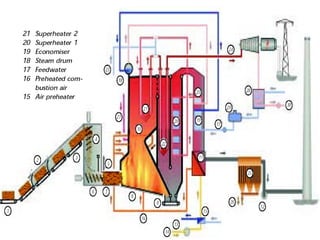
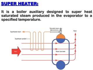
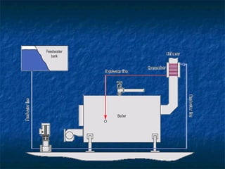
SEQUENCE OF PRESENTATION
 BOILER AUXILIARIES
 BOILER MOUNTINGS
 SAFETY VALVES
BOILER AUXILIARIES:
BOILER AUXILIARIES:
These are the devices incorporated in the boiler
circuit to boost up the efficiency and performance
of the steam generation plant and assist in the
systematic & adequate operation of the boiler unit
for prolonged period.
Whats are they:
Whats are they:
Usually a boiler is fitted with the following
auxiliaries (Accessories):
i)
i) Super heater.
Super heater.
ii)
ii) De-super heater.
De-super heater.
iii)
iii) Economizer.
Economizer.
iv)
iv) Air pre heater.
Air pre heater.
v)
v) Boiler feed pumps.
Boiler feed pumps.
vi)
vi) Forced draft & induced draft fans.
Forced draft & induced draft fans.
vii)
vii) Mechanical Separator.
Mechanical Separator.
Continued..
Continued..
viii)
viii) Equipment tanks:
Equipment tanks:
a) Feed Water Tank.
a) Feed Water Tank.
b) Deaerator
b) Deaerator
c) Continuous blow down expender
d) Drainage expender.
ix)
ix) Chemical Dozing system
Chemical Dozing system
x)
x) Soot blowers & wall blowers
Soot blowers & wall blowers
xi)
xi) Pressure reducing valve
Pressure reducing valve
xii)
xii) Pulverizes and fuel firing system
Pulverizes and fuel firing system
xiii)
xiii) Ash handling system.
Ash handling system.
SUPER HEATER:
SUPER HEATER:
It is a boiler auxiliary designed to super heat
saturated steam produced in the evaporator to a
specified temperature.
CLASSIFICATION SUPER HEATER:
Depending on the mode of heat transfer from the
furnace to super heat surfaces, the super heaters
and divided into:
and divided into:
a)
a) CONVECTIVE SUPER HEATERS
CONVECTIVE SUPER HEATERS
b)
b) RADIANT SUPER HEATERS
RADIANT SUPER HEATERS
c)
c) PLATEN SUPER HEATERS
PLATEN SUPER HEATERS
a) CONVECTIVE SUPER HEATER
Which absorb heat mainly by convention. They are
placed in the convective gas duct.
b) RADIANT SUPER HEATER
Which absorb radiant heat from the flame in the
furnace core.
furnace core.
c) PLATEN SUPER HEATER
That absorb both radiant & convective heat. These are
mounted on the top of the furnace & partially in the flue gas
duct between the convective & radios of heating surface.
KINDS OF SUPER HEATERS DEPLOYED
1.
1. PRIMARY SUPER HEATER
PRIMARY SUPER HEATER
2.
2. INTERMEDIATE SUPER HEATER
INTERMEDIATE SUPER HEATER
1. PRIMARY SUPER HEATER
To super heat the saturated steam produced in the
evaporator.
evaporator.
2. INTERMEDIATE SUPER HEATER
It is to re-heat the turbine exhaust steam to a super
heat temperature once more. Intermediate super
heaters are also called re-heaters.
SUPER HEATING
SUPER HEATING
Production of steam at a temperature higher than
the saturation temperature is called super heating.
DEGREE OF SUPER HEATING
It is the temperature imparted to steam above its
saturation temperature at a given pressure.
HOW CAN THE CONDITION OF SUPER
HEAT BE EXPRESSED
HEAT BE EXPRESSED
This can be done in two ways.
1.
1. In term of Degree of super heater for a given
In term of Degree of super heater for a given
pressure.
pressure.
2.
2. The actual temperature & pressure of the
The actual temperature & pressure of the
steam.
steam.
At steam pressure above the critical point, because
beyond this point no saturation steam exists. So
that term super heat is no longer applicable.
WHEN DOES THE SIGNIFICANCE OF
THE TERM SUPER HEAT FAILS
Wet saturated steam carries water droplets, but
super heater steam has no entrained moisture and
as such the latter is less erosive & corrosive than the
former.
former.
WHY IS SUPER HEATED STEAM LESS
EROSIVE & CORROSIVE THEN WET,
SATUARTED STEAM
SATUARTED STEAM
De Supper is installed with supper heater mainly
due to:
due to:
1.
1. To control the super heated steam
To control the super heated steam
temperature by injecting DM water to supper
heater steam.
heater steam.
2.
2. to produce saturated steam to run the boiler
to produce saturated steam to run the boiler
auxiliaries
auxiliaries
DE SUPPER HEATER
This is the heat recovery
equipment that pick up
heat from the combustion
product of a boiler furnace
to heat up the boiler feed
water
water
ECONOMOZER
ECONOMOZER
Fig. 3.4.3 A shell boiler with an economiser
PURPOSE OF INSTALLATION-
ECONOMIZER
ECONOMIZER
Forming essential parts of a complete system of
steam generating unit, this is installed to conserve
as much heat of fuel combustion in the boiler
furnace as is possible and to increase the capacity
of a boiler or decrease the size of prospective boiler
for a stipulated output.
The fundamental basis of its installations is to
reduce the steam out put cost.
BOILER FEED PUMP
BOILER FEED PUMP
 A pump that feeds boiler water (polished water) to the
A pump that feeds boiler water (polished water) to the
steam drum via the economizer.
 Important criteria of a boiler feed pump
Important criteria of a boiler feed pump
 It must be absolutely positive & reliable under all
It must be absolutely positive & reliable under all
variable operating conditions
 KINDS OF BOILER FEED PUMP
KINDS OF BOILER FEED PUMP
 A) a direct acting pump driven by its own cylinders
A) a direct acting pump driven by its own cylinders
 B) a reciprocal pump driven by a motor or betters to
B) a reciprocal pump driven by a motor or betters to
the machinery
the machinery
 C) a centrifugal pump turbo driven or electrically
C) a centrifugal pump turbo driven or electrically
driven by motor.
driven by motor.
DIRECT ACTING PUMP
DIRECT ACTING PUMP
CLASSIFICATION
CLASSIFICATION
 These may be classified as simplex, duplex
These may be classified as simplex, duplex
and triplex pumps.
and triplex pumps.
 The simplex pump has one engine cylinder
The simplex pump has one engine cylinder
 In duplex and triplex pumps there are two
In duplex and triplex pumps there are two
and three pump cylinders respectively.
KIND OF RECIPROCATING
KIND OF RECIPROCATING PUMPs
PUMPs
 Both plunger driven and piston driven.
Both plunger driven and piston driven.
 NOTE
NOTE
Among the three kind of pumps we will
prefer centrifugal pump as boiler feed pump
due to following reasons.
 Delivery study flow of BFW
Delivery study flow of BFW
 Supplying the largest quantity of boiler feed water
Supplying the largest quantity of boiler feed water
under a given head.
under a given head.
 Accepting load variation most easily.
Accepting load variation most easily.
 Trouble free and smooth operation, less floor space is
Trouble free and smooth operation, less floor space is
required and maintenance cost is low.
PURPOSE OF INSTALLATION OF BOTH
TURBO DRIVEN & MOTOR DRIVEN
CENTRIFUGAL PUMPS
CENTRIFUGAL PUMPS
 During start up, the motor driven pumps are lined up to
During start up, the motor driven pumps are lined up to
establish circulation.
 When the unit is in full operation and steam is available, one or
When the unit is in full operation and steam is available, one or
two turbo driven pumps may be lined up to spare
corresponding number (s) of motor driven pumps for reserve,
rest, repairing or saving of electricity which is costlier than
steam. Motor driven pumps will continue to circulate BFP
through the boiler unit when the latter trips.
 Turbo driven pump is always prefer due to steam is cheaper
Turbo driven pump is always prefer due to steam is cheaper
than electricity.
than electricity.
AIR PRE-HEATERS
AIR PRE-HEATERS
Flue gas–to-air heat exchanger installed in the flue
gas stream leaving the boiler and the combustion
air stream entering the boiler are called air pre
heaters.
heaters.
They are used to transfer heat from the boiler flue
gas to the combustion air.
Boiler efficiency is improved at all loads because
the flue gas temperature is reduced.
An additional benefit may be the potential for
reducing excess air by using pre heated combustion
air.
air.
TYPES OF AIR PRE-HEATERS
There are three general types of air pre-heater:
1.
1. Tubular Air Preheater.
Tubular Air Preheater.
2.
2. Rotary Regenerative Air Preheater.
Rotary Regenerative Air Preheater.
3.
3. Heat Pipe Air Preheater.
Heat Pipe Air Preheater.
1. TUBULAR AIR PREHEATER
The arrangements of a tubular air preheater with flue gas flowing
through the tubes and air flowing around the tubes.
In this design the tubes act as a solid barrier between the flue gas and
the combustion air.
the combustion air.
2. ROTARY RE GENERATIVE AIR PREHEATER
In this exchanger the heating surface are heated in the flue gas stream
and rotate into the air stream where the heat is given up.
A disadvantage of this type is air leaking through the seals into the flue
gas.
gas.
Due to its compact size and flexible installation arrangement, such an air
preheater usually is easier to add to an existing boiler than a tubular air
preheater.
preheater.
3. HEAT PIPE AIR PREHEATER
This exchanger uses heat pipes partially filled with a heater transfer
vaporizing fluid and is a relatively new development.
BLOW DOWN AND DEAERATOR VENT
RECOVERY
RECOVERY
The blowdown water is admitted to the blowdown flash tank.
The heat in the water causes some of the water to flash into
low pressure steam. The steam then is used to heat feed
water in the deaerating heater, which returns the heat to the
boiler. This recovers approximately 50% of the heat in the
blowdown water.
blowdown water.
The water remaining in the blowdown flash tank then is
cooled further in a heat exchanger called a blowdown
cooler.
cooler.
This heat exchanger generally is used to heat feed water
before it enters the deaerating heater , thus returning the
heat to the boiler. The cooled blowdown water with a high
concentration of water chemicals then is discharged to the
sewer. Using this type of heat exchanger recovers
approximately another 25 percent of the heat from the boiler
blowdown.
blowdown.
BOILER MOUNTINGS
BOILER MOUNTINGS
1.
1. Safety and Relief Valves
Safety and Relief Valves
2.
2. Low-water Cut-offs
Low-water Cut-offs
3.
3. Water Feeders
Water Feeders
4.
4. Water gages
Water gages
5.
5. Try Cocks
Try Cocks
1. SAFETY AND RELIEF VALVES
It is necessary to provide a positive protective device on the
boiler to prevent the pressure from exeeding that for which the
vessel was designed. Such automatic firing devices includes the
following:
following:
POP SAFETY VALVE
POP SAFETY VALVE
When the pressure reaches a predetermined point, the valve
pops wide open and tays open untill the pressure drops.
SAFETY RELIEF VALVES
When the pressure reaches a predetermined point, the valve
opens slightly to pass some liquid, on further pressure rise, the
valve pops wide open.
PRESSURE & TEMPERATURE RELIEF VALVE
When the pressure reaches a predetermined point, or if the temp.
approaches the boiling point, either the valve opens or a fusible
element melts.
element melts.
2. LOW-WATER CUT-OFFS
All automatically fired steam boilers are required to have a low-
water cut-off, which will prevent operation of the fuel burner
unless there is adequate water in the boiler. Many hot water
boilers are also equipped with low-water. A typical unit consists a
float-operated switch. The cut-off, may be incorporated into the
water column, or the float may also be included. All units have a
blow-off valve for periodic flusing of collected sediment.
2. WATER FEEDERRS
2. WATER FEEDERRS
The customary practice is to feed water to the boiler automatically
whenever, the water level drops to a predetermined point. At
pressure blow 250 PSIG, a float operated valve is often used, usually
in combination with the low-water cut-off. At higher pressures, it is
comes necessary to depend upon the expansion of a pipe (from
contact with steam) to operate the device. Some combination low-
water cut-off and water feeder units are of the electrode type, passing
electricity through the boiler water.
3. WATER GAGES
3. WATER GAGES
All steam boilers are fitted with a water gage permitting visual
determination of the quantity of water in the boiler. The design of
these gages varies with the pressure to which they are subjected.
They are fitted with shut-off valves (some types work
automatically if the glass breaks) and drain cocks.
4. TRY COCKS
4. TRY COCKS
Valves are provided at three elevations of the gage glass,
allowing the operator to determine if the water level in the boiler
agrees with the gage glass indication.
AUXILIARY EQUIPMENT
AUXILIARY EQUIPMENT
1.
1. Blowdown
Blowdown
2.
2. Instrumentation
Instrumentation
3.
3. Soot-blowers
Soot-blowers
4.
4. Boiler Piping
Boiler Piping
5.
5. Feed Water Injection
Feed Water Injection
6.
6. Whistles
Whistles
7.
7. Feed Water Treatment
Feed Water Treatment
8.
8. Feed Water Injection
Feed Water Injection
1. BLOWDOWN
1. BLOWDOWN
In Boiler requiring quantities of makeup water, there will be a
gradual increase in the concentration of sediment and soluble
salts in the boiler water unless the feed-water is treated
sufficiently to remove all traces of hardness. This material is
removed by blow-down, which may be periodic or continuous.
The hot water will flash into steam as the pressure is relived. It is
customary to condense this steam and cool the blowdown water
prior to discharge to the sewer. With continuous blow-down, it is
feasible to use the process to provide some heat to the feed
water.
water.
2. INSTRUMENTATION
2. INSTRUMENTATION
Steam boilers are required to have a steam pressure gage and a
thermometer. Other instrumentation may include a makeup water
meter, steam flow meter, flue gas thermometer, and other
recording or indicating instruments. Large installation have
elaborate automatic controls for the economizer, feed water
treatment, feed water heater, de-super heater, and air heater, as
well as the steam pressure and temperature control.
3. SOOT BLOWERS
3. SOOT BLOWERS
The fireside passage of the boiler have a tendency to collect soot
and fly ash. Special steam or air lances, permanently installed,
are used to dislodge these combustion products.
4. BOILER PIPING
4. BOILER PIPING
It is necessary, of course, to remove the steam or hot water form
the boiler. The connecting piping, as well as the inter connecting
piping to the super heater and economizer, must have adequate
provisions for expansion without subjecting the boiler
components to strain.
DEAERATION AND
DEAERATION AND
DEOXYGENATION
DEOXYGENATION
 DEAERATION
DEAERATION
Dearation is the process of removing dissolved
corrosive gases (Oxygen & Carbon mono dioxide)
This process is also called degasification. Dearation is
a thermal process, water heated to bring about
degasification.
degasification.
DEOXYGENATION
DEOXYGENATION
It is the process of removal of only oxygen.
deoxygenation is carried out mainly by chemical
techniques.
techniques.
TYPES OF DEARATORS
TYPES OF DEARATORS
Types
Types working pressure
working pressure
 Vacuum dearator 0.116 MN/m2
Vacuum dearator 0.116 MN/m2
 Atmosphere dearator
Atmosphere dearator
0.12-0.17MN/m2
0.12-0.17MN/m2
 High pressure dearator
High pressure dearator 0.17-0.7MN/m2
0.17-0.7MN/m2
VACUUM DEARATOR
VACUUM DEARATOR
Deaeration is carried out in vacuum at a
Deaeration is carried out in vacuum at a
pressure less than atmospheric pressure
APPLICATIONS
APPLICATIONS
Low capacity, low pressure boiler,
requiring water at a temperature less
than 373K
than 373K
ATMOSPHERIC DEAERATOR
 Atmospheric deaerator can be divided
Atmospheric deaerator can be divided
into direct contact ( mixing) deaerator
and over heated water deaerators
FUNCTION OF DIRECT –CONTACT
DEAERATORS
DEAERATORS
 They consists of a deaerator column fitted
They consists of a deaerator column fitted
on top of the storage tank
 The deaerator column is hollow cylindrical
The deaerator column is hollow cylindrical
vessel provided with
a) Perforated, horizontal trays arranged
one above the other.
b) Water distribution direct at the top
c) Steam distribution at the bottom
FUNCTION OF DIRECT –CONTACT
DEAERATORS
DEAERATORS
 Feed water enters the deaerator from the top and is evenly
Feed water enters the deaerator from the top and is evenly
distributed by means of the distributing device into the perforated
trays fitted at the bottom. Water fills the perforations ( dia5-7mm)
and rain down and comes in contact with heating steam delivered
into the lower portion of the deaerator columns through the
steam distributor. As a result of heat exchange between the steam
going up and the feed water stream flowing down, the water gets
heated upto its boiling points and the gases( O2 and CO2)
dissolved in it or transfer to the gas face. These gases together
with non-condensing vapour are vented into the atmosphere
through a vent valve or pass into a vent condenser where the
steam is condensed and the O2 and Co2 are vented.
 The deaerated water is collected in the storage tank which is fitted
The deaerated water is collected in the storage tank which is fitted
with gauge glass, pressure gauge and hydraulic seals to avoid the
formation of high pressure or vacuum in the deaerator
TYPE OF DEAERATORS IN
ACCORDANCE WITH THE MODE
OF STEAM WATER
OF STEAM WATER DISTRIBUTION
DISTRIBUTION
 Automizing deaerator
Automizing deaerator
 Tray type deaerator
Tray type deaerator
 Film type deaerator
Film type deaerator
CONDITION FOR SUCCESS
OPERATION OF THE DEAERATOR
 The temperature of deaerated water must be equal to the saturation
The temperature of deaerated water must be equal to the saturation
temperature of water corresponding to the pressure at which the
deaerator operates.
deaerator operates.
 Sufficient heating steam must be delivered to the deaerator to ensure
Sufficient heating steam must be delivered to the deaerator to ensure
continuous boiling of water undergoing deaeration.
 The feed water charged to the deaerator must be disintegrated into
The feed water charged to the deaerator must be disintegrated into
fine droplets to ensure better heat transfer between the heating steam
and feed water. Hence perforated trays find widest application.
 The deaerator must be provided with sufficient venting to purge all the
The deaerator must be provided with sufficient venting to purge all the
non-condensing gases out of the system and to ensure minimum
partial pressures of these gases in the upper part of the deaerator.
 If two or more deaerator are operated in parallel, all must be operated
If two or more deaerator are operated in parallel, all must be operated
at same pressure.
at same pressure.

BOILER AUXILIRIES in Mechanical engineering

  • 3.
    SEQUENCE OF PRESENTATION SEQUENCEOF PRESENTATION  BOILER AUXILIARIES  BOILER MOUNTINGS  SAFETY VALVES
  • 4.
    BOILER AUXILIARIES: BOILER AUXILIARIES: Theseare the devices incorporated in the boiler These are the devices incorporated in the boiler circuit to boost up the efficiency and performance circuit to boost up the efficiency and performance of the steam generation plant and assist in the of the steam generation plant and assist in the systematic & adequate operation of the boiler unit systematic & adequate operation of the boiler unit for prolonged period. for prolonged period.
  • 5.
    Whats are they: Whatsare they: Usually a boiler is fitted with the following Usually a boiler is fitted with the following auxiliaries (Accessories): auxiliaries (Accessories): i) i) Super heater. Super heater. ii) ii) De-super heater. De-super heater. iii) iii) Economizer. Economizer. iv) iv) Air pre heater. Air pre heater. v) v) Boiler feed pumps. Boiler feed pumps. vi) vi) Forced draft & induced draft fans. Forced draft & induced draft fans. vii) vii) Mechanical Separator. Mechanical Separator. Continued.. Continued..
  • 6.
    viii) viii) Equipment tanks: Equipmenttanks: a) Feed Water Tank. a) Feed Water Tank. b) Deaerator b) Deaerator c) Continuous blow down expender c) Continuous blow down expender d) Drainage expender. d) Drainage expender. ix) ix) Chemical Dozing system Chemical Dozing system x) x) Soot blowers & wall blowers Soot blowers & wall blowers xi) xi) Pressure reducing valve Pressure reducing valve xii) xii) Pulverizes and fuel firing system Pulverizes and fuel firing system xiii) xiii) Ash handling system. Ash handling system.
  • 8.
    SUPER HEATER: SUPER HEATER: Itis a boiler auxiliary designed to super heat It is a boiler auxiliary designed to super heat saturated steam produced in the evaporator to a saturated steam produced in the evaporator to a specified temperature. specified temperature.
  • 9.
    CLASSIFICATION SUPER HEATER: CLASSIFICATIONSUPER HEATER: Depending on the mode of heat transfer from the Depending on the mode of heat transfer from the furnace to super heat surfaces, the super heaters furnace to super heat surfaces, the super heaters and divided into: and divided into: a) a) CONVECTIVE SUPER HEATERS CONVECTIVE SUPER HEATERS b) b) RADIANT SUPER HEATERS RADIANT SUPER HEATERS c) c) PLATEN SUPER HEATERS PLATEN SUPER HEATERS
  • 10.
    a) CONVECTIVE SUPERHEATER a) CONVECTIVE SUPER HEATER Which absorb heat mainly by convention. They are Which absorb heat mainly by convention. They are placed in the convective gas duct. placed in the convective gas duct. b) RADIANT SUPER HEATER b) RADIANT SUPER HEATER Which absorb radiant heat from the flame in the Which absorb radiant heat from the flame in the furnace core. furnace core. c) PLATEN SUPER HEATER c) PLATEN SUPER HEATER That absorb both radiant & convective heat. These are That absorb both radiant & convective heat. These are mounted on the top of the furnace & partially in the flue gas mounted on the top of the furnace & partially in the flue gas duct between the convective & radios of heating surface. duct between the convective & radios of heating surface.
  • 11.
    KINDS OF SUPERHEATERS DEPLOYED KINDS OF SUPER HEATERS DEPLOYED 1. 1. PRIMARY SUPER HEATER PRIMARY SUPER HEATER 2. 2. INTERMEDIATE SUPER HEATER INTERMEDIATE SUPER HEATER
  • 12.
    1. PRIMARY SUPERHEATER 1. PRIMARY SUPER HEATER To super heat the saturated steam produced in the To super heat the saturated steam produced in the evaporator. evaporator. 2. INTERMEDIATE SUPER HEATER 2. INTERMEDIATE SUPER HEATER It is to re-heat the turbine exhaust steam to a super It is to re-heat the turbine exhaust steam to a super heat temperature once more. Intermediate super heat temperature once more. Intermediate super heaters are also called re-heaters. heaters are also called re-heaters.
  • 13.
    SUPER HEATING SUPER HEATING Productionof steam at a temperature higher than Production of steam at a temperature higher than the saturation temperature is called super heating. the saturation temperature is called super heating. DEGREE OF SUPER HEATING DEGREE OF SUPER HEATING It is the temperature imparted to steam above its It is the temperature imparted to steam above its saturation temperature at a given pressure. saturation temperature at a given pressure.
  • 14.
    HOW CAN THECONDITION OF SUPER HOW CAN THE CONDITION OF SUPER HEAT BE EXPRESSED HEAT BE EXPRESSED This can be done in two ways. This can be done in two ways. 1. 1. In term of Degree of super heater for a given In term of Degree of super heater for a given pressure. pressure. 2. 2. The actual temperature & pressure of the The actual temperature & pressure of the steam. steam.
  • 15.
    At steam pressureabove the critical point, because At steam pressure above the critical point, because beyond this point no saturation steam exists. So beyond this point no saturation steam exists. So that term super heat is no longer applicable. that term super heat is no longer applicable. WHEN DOES THE SIGNIFICANCE OF WHEN DOES THE SIGNIFICANCE OF THE TERM SUPER HEAT FAILS THE TERM SUPER HEAT FAILS
  • 16.
    Wet saturated steamcarries water droplets, but Wet saturated steam carries water droplets, but super heater steam has no entrained moisture and super heater steam has no entrained moisture and as such the latter is less erosive & corrosive than the as such the latter is less erosive & corrosive than the former. former. WHY IS SUPER HEATED STEAM LESS WHY IS SUPER HEATED STEAM LESS EROSIVE & CORROSIVE THEN WET, EROSIVE & CORROSIVE THEN WET, SATUARTED STEAM SATUARTED STEAM
  • 17.
    De Supper isinstalled with supper heater mainly De Supper is installed with supper heater mainly due to: due to: 1. 1. To control the super heated steam To control the super heated steam temperature by injecting DM water to supper temperature by injecting DM water to supper heater steam. heater steam. 2. 2. to produce saturated steam to run the boiler to produce saturated steam to run the boiler auxiliaries auxiliaries DE SUPPER HEATER
  • 18.
    This is theheat recovery This is the heat recovery equipment that pick up equipment that pick up heat from the combustion heat from the combustion product of a boiler furnace product of a boiler furnace to heat up the boiler feed to heat up the boiler feed water water ECONOMOZER ECONOMOZER
  • 19.
    Fig. 3.4.3 Ashell boiler with an economiser Fig. 3.4.3 A shell boiler with an economiser
  • 20.
    PURPOSE OF INSTALLATION- PURPOSEOF INSTALLATION- ECONOMIZER ECONOMIZER Forming essential parts of a complete system of Forming essential parts of a complete system of steam generating unit, this is installed to conserve steam generating unit, this is installed to conserve as much heat of fuel combustion in the boiler as much heat of fuel combustion in the boiler furnace as is possible and to increase the capacity furnace as is possible and to increase the capacity of a boiler or decrease the size of prospective boiler of a boiler or decrease the size of prospective boiler for a stipulated output. for a stipulated output. The fundamental basis of its installations is to The fundamental basis of its installations is to reduce the steam out put cost. reduce the steam out put cost.
  • 21.
    BOILER FEED PUMP BOILERFEED PUMP  A pump that feeds boiler water (polished water) to the A pump that feeds boiler water (polished water) to the steam drum via the economizer. steam drum via the economizer.  Important criteria of a boiler feed pump Important criteria of a boiler feed pump  It must be absolutely positive & reliable under all It must be absolutely positive & reliable under all variable operating conditions variable operating conditions  KINDS OF BOILER FEED PUMP KINDS OF BOILER FEED PUMP  A) a direct acting pump driven by its own cylinders A) a direct acting pump driven by its own cylinders  B) a reciprocal pump driven by a motor or betters to B) a reciprocal pump driven by a motor or betters to the machinery the machinery  C) a centrifugal pump turbo driven or electrically C) a centrifugal pump turbo driven or electrically driven by motor. driven by motor.
  • 22.
    DIRECT ACTING PUMP DIRECTACTING PUMP CLASSIFICATION CLASSIFICATION  These may be classified as simplex, duplex These may be classified as simplex, duplex and triplex pumps. and triplex pumps.  The simplex pump has one engine cylinder The simplex pump has one engine cylinder  In duplex and triplex pumps there are two In duplex and triplex pumps there are two and three pump cylinders respectively. and three pump cylinders respectively.
  • 23.
    KIND OF RECIPROCATING KINDOF RECIPROCATING PUMPs PUMPs  Both plunger driven and piston driven. Both plunger driven and piston driven.  NOTE NOTE Among the three kind of pumps we will Among the three kind of pumps we will prefer centrifugal pump as boiler feed pump prefer centrifugal pump as boiler feed pump due to following reasons. due to following reasons.  Delivery study flow of BFW Delivery study flow of BFW  Supplying the largest quantity of boiler feed water Supplying the largest quantity of boiler feed water under a given head. under a given head.  Accepting load variation most easily. Accepting load variation most easily.  Trouble free and smooth operation, less floor space is Trouble free and smooth operation, less floor space is required and maintenance cost is low. required and maintenance cost is low.
  • 24.
    PURPOSE OF INSTALLATIONOF BOTH PURPOSE OF INSTALLATION OF BOTH TURBO DRIVEN & MOTOR DRIVEN TURBO DRIVEN & MOTOR DRIVEN CENTRIFUGAL PUMPS CENTRIFUGAL PUMPS  During start up, the motor driven pumps are lined up to During start up, the motor driven pumps are lined up to establish circulation. establish circulation.  When the unit is in full operation and steam is available, one or When the unit is in full operation and steam is available, one or two turbo driven pumps may be lined up to spare two turbo driven pumps may be lined up to spare corresponding number (s) of motor driven pumps for reserve, corresponding number (s) of motor driven pumps for reserve, rest, repairing or saving of electricity which is costlier than rest, repairing or saving of electricity which is costlier than steam. Motor driven pumps will continue to circulate BFP steam. Motor driven pumps will continue to circulate BFP through the boiler unit when the latter trips. through the boiler unit when the latter trips.  Turbo driven pump is always prefer due to steam is cheaper Turbo driven pump is always prefer due to steam is cheaper than electricity. than electricity.
  • 25.
    AIR PRE-HEATERS AIR PRE-HEATERS Fluegas–to-air heat exchanger installed in the flue Flue gas–to-air heat exchanger installed in the flue gas stream leaving the boiler and the combustion gas stream leaving the boiler and the combustion air stream entering the boiler are called air pre air stream entering the boiler are called air pre heaters. heaters. They are used to transfer heat from the boiler flue They are used to transfer heat from the boiler flue gas to the combustion air. gas to the combustion air. Boiler efficiency is improved at all loads because Boiler efficiency is improved at all loads because the flue gas temperature is reduced. the flue gas temperature is reduced. An additional benefit may be the potential for An additional benefit may be the potential for reducing excess air by using pre heated combustion reducing excess air by using pre heated combustion air. air.
  • 26.
    TYPES OF AIRPRE-HEATERS TYPES OF AIR PRE-HEATERS There are three general types of air pre-heater: There are three general types of air pre-heater: 1. 1. Tubular Air Preheater. Tubular Air Preheater. 2. 2. Rotary Regenerative Air Preheater. Rotary Regenerative Air Preheater. 3. 3. Heat Pipe Air Preheater. Heat Pipe Air Preheater.
  • 27.
    1. TUBULAR AIRPREHEATER 1. TUBULAR AIR PREHEATER The arrangements of a tubular air preheater with flue gas flowing The arrangements of a tubular air preheater with flue gas flowing through the tubes and air flowing around the tubes. through the tubes and air flowing around the tubes. In this design the tubes act as a solid barrier between the flue gas and In this design the tubes act as a solid barrier between the flue gas and the combustion air. the combustion air. 2. ROTARY RE GENERATIVE AIR PREHEATER 2. ROTARY RE GENERATIVE AIR PREHEATER In this exchanger the heating surface are heated in the flue gas stream In this exchanger the heating surface are heated in the flue gas stream and rotate into the air stream where the heat is given up. and rotate into the air stream where the heat is given up. A disadvantage of this type is air leaking through the seals into the flue A disadvantage of this type is air leaking through the seals into the flue gas. gas. Due to its compact size and flexible installation arrangement, such an air Due to its compact size and flexible installation arrangement, such an air preheater usually is easier to add to an existing boiler than a tubular air preheater usually is easier to add to an existing boiler than a tubular air preheater. preheater. 3. HEAT PIPE AIR PREHEATER 3. HEAT PIPE AIR PREHEATER This exchanger uses heat pipes partially filled with a heater transfer This exchanger uses heat pipes partially filled with a heater transfer vaporizing fluid and is a relatively new development. vaporizing fluid and is a relatively new development.
  • 28.
    BLOW DOWN ANDDEAERATOR VENT BLOW DOWN AND DEAERATOR VENT RECOVERY RECOVERY The blowdown water is admitted to the blowdown flash tank. The blowdown water is admitted to the blowdown flash tank. The heat in the water causes some of the water to flash into The heat in the water causes some of the water to flash into low pressure steam. The steam then is used to heat feed low pressure steam. The steam then is used to heat feed water in the deaerating heater, which returns the heat to the water in the deaerating heater, which returns the heat to the boiler. This recovers approximately 50% of the heat in the boiler. This recovers approximately 50% of the heat in the blowdown water. blowdown water. The water remaining in the blowdown flash tank then is The water remaining in the blowdown flash tank then is cooled further in a heat exchanger called a blowdown cooled further in a heat exchanger called a blowdown cooler. cooler. This heat exchanger generally is used to heat feed water This heat exchanger generally is used to heat feed water before it enters the deaerating heater , thus returning the before it enters the deaerating heater , thus returning the heat to the boiler. The cooled blowdown water with a high heat to the boiler. The cooled blowdown water with a high concentration of water chemicals then is discharged to the concentration of water chemicals then is discharged to the sewer. Using this type of heat exchanger recovers sewer. Using this type of heat exchanger recovers approximately another 25 percent of the heat from the boiler approximately another 25 percent of the heat from the boiler blowdown. blowdown.
  • 29.
    BOILER MOUNTINGS BOILER MOUNTINGS 1. 1.Safety and Relief Valves Safety and Relief Valves 2. 2. Low-water Cut-offs Low-water Cut-offs 3. 3. Water Feeders Water Feeders 4. 4. Water gages Water gages 5. 5. Try Cocks Try Cocks
  • 30.
    1. SAFETY ANDRELIEF VALVES 1. SAFETY AND RELIEF VALVES It is necessary to provide a positive protective device on the It is necessary to provide a positive protective device on the boiler to prevent the pressure from exeeding that for which the boiler to prevent the pressure from exeeding that for which the vessel was designed. Such automatic firing devices includes the vessel was designed. Such automatic firing devices includes the following: following: POP SAFETY VALVE POP SAFETY VALVE When the pressure reaches a predetermined point, the valve When the pressure reaches a predetermined point, the valve pops wide open and tays open untill the pressure drops. pops wide open and tays open untill the pressure drops. SAFETY RELIEF VALVES SAFETY RELIEF VALVES When the pressure reaches a predetermined point, the valve When the pressure reaches a predetermined point, the valve opens slightly to pass some liquid, on further pressure rise, the opens slightly to pass some liquid, on further pressure rise, the valve pops wide open. valve pops wide open. PRESSURE & TEMPERATURE RELIEF VALVE PRESSURE & TEMPERATURE RELIEF VALVE When the pressure reaches a predetermined point, or if the temp. When the pressure reaches a predetermined point, or if the temp. approaches the boiling point, either the valve opens or a fusible approaches the boiling point, either the valve opens or a fusible element melts. element melts.
  • 31.
    2. LOW-WATER CUT-OFFS 2.LOW-WATER CUT-OFFS All automatically fired steam boilers are required to have a low- All automatically fired steam boilers are required to have a low- water cut-off, which will prevent operation of the fuel burner water cut-off, which will prevent operation of the fuel burner unless there is adequate water in the boiler. Many hot water unless there is adequate water in the boiler. Many hot water boilers are also equipped with low-water. A typical unit consists a boilers are also equipped with low-water. A typical unit consists a float-operated switch. The cut-off, may be incorporated into the float-operated switch. The cut-off, may be incorporated into the water column, or the float may also be included. All units have a water column, or the float may also be included. All units have a blow-off valve for periodic flusing of collected sediment. blow-off valve for periodic flusing of collected sediment. 2. WATER FEEDERRS 2. WATER FEEDERRS The customary practice is to feed water to the boiler automatically The customary practice is to feed water to the boiler automatically whenever, the water level drops to a predetermined point. At whenever, the water level drops to a predetermined point. At pressure blow 250 PSIG, a float operated valve is often used, usually pressure blow 250 PSIG, a float operated valve is often used, usually in combination with the low-water cut-off. At higher pressures, it is in combination with the low-water cut-off. At higher pressures, it is comes necessary to depend upon the expansion of a pipe (from comes necessary to depend upon the expansion of a pipe (from contact with steam) to operate the device. Some combination low- contact with steam) to operate the device. Some combination low- water cut-off and water feeder units are of the electrode type, passing water cut-off and water feeder units are of the electrode type, passing electricity through the boiler water. electricity through the boiler water.
  • 32.
    3. WATER GAGES 3.WATER GAGES All steam boilers are fitted with a water gage permitting visual All steam boilers are fitted with a water gage permitting visual determination of the quantity of water in the boiler. The design of determination of the quantity of water in the boiler. The design of these gages varies with the pressure to which they are subjected. these gages varies with the pressure to which they are subjected. They are fitted with shut-off valves (some types work They are fitted with shut-off valves (some types work automatically if the glass breaks) and drain cocks. automatically if the glass breaks) and drain cocks. 4. TRY COCKS 4. TRY COCKS Valves are provided at three elevations of the gage glass, Valves are provided at three elevations of the gage glass, allowing the operator to determine if the water level in the boiler allowing the operator to determine if the water level in the boiler agrees with the gage glass indication. agrees with the gage glass indication.
  • 33.
    AUXILIARY EQUIPMENT AUXILIARY EQUIPMENT 1. 1.Blowdown Blowdown 2. 2. Instrumentation Instrumentation 3. 3. Soot-blowers Soot-blowers 4. 4. Boiler Piping Boiler Piping 5. 5. Feed Water Injection Feed Water Injection 6. 6. Whistles Whistles 7. 7. Feed Water Treatment Feed Water Treatment 8. 8. Feed Water Injection Feed Water Injection
  • 34.
    1. BLOWDOWN 1. BLOWDOWN InBoiler requiring quantities of makeup water, there will be a In Boiler requiring quantities of makeup water, there will be a gradual increase in the concentration of sediment and soluble gradual increase in the concentration of sediment and soluble salts in the boiler water unless the feed-water is treated salts in the boiler water unless the feed-water is treated sufficiently to remove all traces of hardness. This material is sufficiently to remove all traces of hardness. This material is removed by blow-down, which may be periodic or continuous. removed by blow-down, which may be periodic or continuous. The hot water will flash into steam as the pressure is relived. It is The hot water will flash into steam as the pressure is relived. It is customary to condense this steam and cool the blowdown water customary to condense this steam and cool the blowdown water prior to discharge to the sewer. With continuous blow-down, it is prior to discharge to the sewer. With continuous blow-down, it is feasible to use the process to provide some heat to the feed feasible to use the process to provide some heat to the feed water. water. 2. INSTRUMENTATION 2. INSTRUMENTATION Steam boilers are required to have a steam pressure gage and a Steam boilers are required to have a steam pressure gage and a thermometer. Other instrumentation may include a makeup water thermometer. Other instrumentation may include a makeup water meter, steam flow meter, flue gas thermometer, and other meter, steam flow meter, flue gas thermometer, and other recording or indicating instruments. Large installation have recording or indicating instruments. Large installation have elaborate automatic controls for the economizer, feed water elaborate automatic controls for the economizer, feed water treatment, feed water heater, de-super heater, and air heater, as treatment, feed water heater, de-super heater, and air heater, as well as the steam pressure and temperature control. well as the steam pressure and temperature control.
  • 35.
    3. SOOT BLOWERS 3.SOOT BLOWERS The fireside passage of the boiler have a tendency to collect soot The fireside passage of the boiler have a tendency to collect soot and fly ash. Special steam or air lances, permanently installed, and fly ash. Special steam or air lances, permanently installed, are used to dislodge these combustion products. are used to dislodge these combustion products. 4. BOILER PIPING 4. BOILER PIPING It is necessary, of course, to remove the steam or hot water form It is necessary, of course, to remove the steam or hot water form the boiler. The connecting piping, as well as the inter connecting the boiler. The connecting piping, as well as the inter connecting piping to the super heater and economizer, must have adequate piping to the super heater and economizer, must have adequate provisions for expansion without subjecting the boiler provisions for expansion without subjecting the boiler components to strain. components to strain.
  • 36.
    DEAERATION AND DEAERATION AND DEOXYGENATION DEOXYGENATION DEAERATION DEAERATION Dearation is the process of removing dissolved Dearation is the process of removing dissolved corrosive gases (Oxygen & Carbon mono dioxide) corrosive gases (Oxygen & Carbon mono dioxide) This process is also called degasification. Dearation is This process is also called degasification. Dearation is a thermal process, water heated to bring about a thermal process, water heated to bring about degasification. degasification. DEOXYGENATION DEOXYGENATION It is the process of removal of only oxygen. It is the process of removal of only oxygen. deoxygenation is carried out mainly by chemical deoxygenation is carried out mainly by chemical techniques. techniques.
  • 37.
    TYPES OF DEARATORS TYPESOF DEARATORS Types Types working pressure working pressure  Vacuum dearator 0.116 MN/m2 Vacuum dearator 0.116 MN/m2  Atmosphere dearator Atmosphere dearator 0.12-0.17MN/m2 0.12-0.17MN/m2  High pressure dearator High pressure dearator 0.17-0.7MN/m2 0.17-0.7MN/m2
  • 38.
    VACUUM DEARATOR VACUUM DEARATOR Deaerationis carried out in vacuum at a Deaeration is carried out in vacuum at a pressure less than atmospheric pressure pressure less than atmospheric pressure APPLICATIONS APPLICATIONS Low capacity, low pressure boiler, Low capacity, low pressure boiler, requiring water at a temperature less requiring water at a temperature less than 373K than 373K
  • 39.
    ATMOSPHERIC DEAERATOR ATMOSPHERIC DEAERATOR Atmospheric deaerator can be divided Atmospheric deaerator can be divided into direct contact ( mixing) deaerator into direct contact ( mixing) deaerator and over heated water deaerators and over heated water deaerators
  • 40.
    FUNCTION OF DIRECT–CONTACT FUNCTION OF DIRECT –CONTACT DEAERATORS DEAERATORS  They consists of a deaerator column fitted They consists of a deaerator column fitted on top of the storage tank on top of the storage tank  The deaerator column is hollow cylindrical The deaerator column is hollow cylindrical vessel provided with vessel provided with a) Perforated, horizontal trays arranged a) Perforated, horizontal trays arranged one above the other. one above the other. b) Water distribution direct at the top b) Water distribution direct at the top c) Steam distribution at the bottom c) Steam distribution at the bottom
  • 41.
    FUNCTION OF DIRECT–CONTACT FUNCTION OF DIRECT –CONTACT DEAERATORS DEAERATORS  Feed water enters the deaerator from the top and is evenly Feed water enters the deaerator from the top and is evenly distributed by means of the distributing device into the perforated distributed by means of the distributing device into the perforated trays fitted at the bottom. Water fills the perforations ( dia5-7mm) trays fitted at the bottom. Water fills the perforations ( dia5-7mm) and rain down and comes in contact with heating steam delivered and rain down and comes in contact with heating steam delivered into the lower portion of the deaerator columns through the into the lower portion of the deaerator columns through the steam distributor. As a result of heat exchange between the steam steam distributor. As a result of heat exchange between the steam going up and the feed water stream flowing down, the water gets going up and the feed water stream flowing down, the water gets heated upto its boiling points and the gases( O2 and CO2) heated upto its boiling points and the gases( O2 and CO2) dissolved in it or transfer to the gas face. These gases together dissolved in it or transfer to the gas face. These gases together with non-condensing vapour are vented into the atmosphere with non-condensing vapour are vented into the atmosphere through a vent valve or pass into a vent condenser where the through a vent valve or pass into a vent condenser where the steam is condensed and the O2 and Co2 are vented. steam is condensed and the O2 and Co2 are vented.  The deaerated water is collected in the storage tank which is fitted The deaerated water is collected in the storage tank which is fitted with gauge glass, pressure gauge and hydraulic seals to avoid the with gauge glass, pressure gauge and hydraulic seals to avoid the formation of high pressure or vacuum in the deaerator formation of high pressure or vacuum in the deaerator
  • 42.
    TYPE OF DEAERATORSIN TYPE OF DEAERATORS IN ACCORDANCE WITH THE MODE ACCORDANCE WITH THE MODE OF STEAM WATER OF STEAM WATER DISTRIBUTION DISTRIBUTION  Automizing deaerator Automizing deaerator  Tray type deaerator Tray type deaerator  Film type deaerator Film type deaerator
  • 43.
    CONDITION FOR SUCCESS CONDITIONFOR SUCCESS OPERATION OF THE DEAERATOR OPERATION OF THE DEAERATOR  The temperature of deaerated water must be equal to the saturation The temperature of deaerated water must be equal to the saturation temperature of water corresponding to the pressure at which the temperature of water corresponding to the pressure at which the deaerator operates. deaerator operates.  Sufficient heating steam must be delivered to the deaerator to ensure Sufficient heating steam must be delivered to the deaerator to ensure continuous boiling of water undergoing deaeration. continuous boiling of water undergoing deaeration.  The feed water charged to the deaerator must be disintegrated into The feed water charged to the deaerator must be disintegrated into fine droplets to ensure better heat transfer between the heating steam fine droplets to ensure better heat transfer between the heating steam and feed water. Hence perforated trays find widest application. and feed water. Hence perforated trays find widest application.  The deaerator must be provided with sufficient venting to purge all the The deaerator must be provided with sufficient venting to purge all the non-condensing gases out of the system and to ensure minimum non-condensing gases out of the system and to ensure minimum partial pressures of these gases in the upper part of the deaerator. partial pressures of these gases in the upper part of the deaerator.  If two or more deaerator are operated in parallel, all must be operated If two or more deaerator are operated in parallel, all must be operated at same pressure. at same pressure.