
Recommended
Recommended
More Related Content
What's hot
What's hot (20)
Similar to Horizontal or Vertical Air Handling Unit with Coil Options
Similar to Horizontal or Vertical Air Handling Unit with Coil Options (20)
More from Oliverh Kalprit
More from Oliverh Kalprit (20)
Recently uploaded
Recently uploaded (20)
Horizontal or Vertical Air Handling Unit with Coil Options
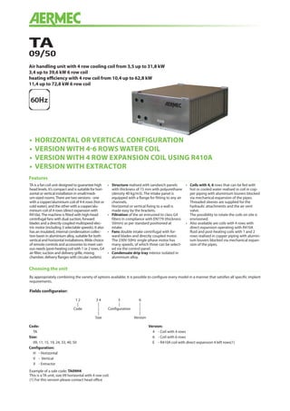
- 1. • HORIZONTAL OR VERTICAL CONFIGURATION • VERSION WITH 4-6 ROWS WATER COIL • VERSION WITH 4 ROW EXPANSION COIL USING R410A • VERSION WITH EXTRACTOR TA 09/50 Air handling unit with 4 row cooling coil from 3,5 up to 31,8 kW 3,4 up to 39,6 kW 6 row coil heating efficiency with 4 row coil from 10,4 up to 62,8 kW 11,4 up to 72,8 kW 6 row coil TA is a fan coil unit designed to guarantee high head levels. It’s compact and is suitable for hori- zontal or vertical installation in small/medi- um-sized rooms.There are two versions - one with a copper/aluminium coil of 4-6 rows (hot or cold water), and the other with a copper/alu- minium coil of 4 rows (direct expansion with R410a).The machine is fitted with high-head centrifugal fans with dual suction, forward blades and a directly coupled multispeed elec- tric motor (including 3 selectable speeds). It also has an insulated, internal condensation collec- tion basin in aluminium alloy, suitable for both vertical and horizontal installations.Wide choice of remote controls and accessories to meet vari- ous needs (post-heating coil with 1 or 2 rows, G4 air filter, suction and delivery grille, mixing chamber, delivery flanges with circular outlets). • Structure realised with sandwich panels with thickness of 15 mm with polyurethane (density 40 kg/m3). The intake panel is equipped with a flange for fitting to any air channels. Horizontal or vertical fixing to a wall is made easy by the brackets. • Filtration of the air entrusted to class G4 filters in compliance with EN779 (thickness 50mm) as per standard positioned at intake. • Fans double intake centrifugal with for- ward blades and directly coupled motor. The 230V-50Hz single-phase motor has many speeds, of which three can be select- ed via the control panel. • Condensate drip tray interior isolated in aluminium alloy. • Coils with 4, 6 rows that can be fed with hot or cooled water realised in coil in cop- per piping with aluminium louvers blocked via mechanical expansion of the pipes. Threaded sleeves are supplied for the hydraulic attachments and the air vent valve. The possibility to rotate the coils on site is envisioned. • Also available are coils with 4 rows with direct expansion operating with R410A fluid and post-heating coils with 1 and 2 rows realised in copper piping with alumin- ium louvers blocked via mechanical expan- sion of the pipes. Features By appropriately combining the variety of options available, it is possible to configure every model in a manner that satisfies all specific implant requirements. Example of a sale code: TA09H4 This is a TA unit, size 09 horizontal with 4 row coil. (1) For this version please contact head office Choosing the unit Code: TA Size: 09, 11, 15, 19, 24, 33, 40, 50 Configuration: H - Horizontal V - Vertical X - Extractor Version: 4 - Coil with 4 rows 6 - Coil with 6 rows E - R410A coil with direct expansion 4 left rows(1) Fields configurator: 1 2 3 4 5 6 | | | | Code | Configuration | | | Size Version
- 2. • M2S 2 damper mixing chamber Galvanised sheet steel section complete with two air calibration dampers with gal- vanised sheet steel louvers. Louver pitch 50 mm; regulation pin in gal- vanised steel with diameter 8 mm mecha- nisation. • M3S 3 damper mixing chamber Galvanised sheet steel section complete with three air calibration dampers and gal- vanised sheet steel louvers. Louver pitch 50 mm; regulation pins in gal- vanised steel with diameter 8 mm mecha- nisation. Va must be coupled with the VRF accessory • FTF Soft bag filters section Galvanised sheet steel section complete with soft bag filters with F6 filtration level. For different filtrations, contact the AERMEC technical-sales dept. • B1R 1 row water coil For 4 pipe systems, positioned internally, downstream from the main coil. Threaded sleeves are supplied for the hydraulic attachments and the air vent valve. • B2R 2 row water coil For 4 pipe systems, positioned internally, downstream from the main coil. Threaded sleeves are supplied for the hydrau- lic attachments and the air vent valve. • VCT 2-way or 3-way valve These are 2-way and 3-way ball valves made of bronze, with female/female connections that can be servo-activated via servo commands. The VCT valves do not have fittings and pipes for water connections, which are the installer’s responsibility. These can be commanded via control panels (accessories) which are enabled for the valve control function. Consult the control panel cha- racteristics before selecting a panel. • VCTATwo or three-way valve actuator contact head office • PBE Section with post-heating coil The electric coil is made up from armoured resistances equipped with double safety thermostat. • SSL Module with seven silencers Galvanised sheet steel section complete with seven silencers in mineral wool covered with a polyethylene film to prevent exfoliation. • S2Z Damper with 2 areas (70-30%) Galvanised sheet steel damper with opposite louvers for the mixture of the external air flow and the flow of recirculation air. Louver pitch 50 mm; regulation pin in galvanised steel with diameter 8 mm mechanisation. • VRF Recovery fan section with G4 filter Fan unit, equipped with electronic varistor of the number of revs. contained in a sec- tion in galvanised sheet steel equipped with flat filters with G4 efficiency (EN779). • PMM Plenum with multiple circular flows Plenum equipped with sandwich panelling with thickness of 15 mm in galvanised steel with polyurethane insulation. The plenum is supplied with multi-diameter circular attach- ments (200 mm, 180 mm and 150 mm) in plas- tic to allow the connection of circular conduits. • PMC Closed flow plenum Plenum closed equipped with sandwich panelling with thickness of 15 mm in galva- nised steel with polyurethane insulation. The plenum allows to turn the flow by 90°. The opening of the flow hole is the install- er’s responsibility. • SAS Intake damper Air calibration damper with galvanised sheet steel louvers. Louver pitch 50 mm; regulation pin in gal- vanised steel with diameter 8 mm mecha- nisation. • GMD Flow grid with moveable louvers Grid with double order of moveable lou- vers for the introduction of air into the room to be conditioned. It can be installed directly onto the appliance by removing the flanges or on the wall. • GAP Intake grid With fixed louvers inclined by 45°; can be installed directly onto the appliance by removing the flanges or on the wall. • FPI G4 flange filters • PX Switch-over only control panel • WMT 05 Electro-mechanical thermostat For fan coils installed in 2 pipe systems The panel must be installed on the wall and protected electrically by an internal fuse. Has the following functions: on/off switch; cursor for the selection of heating/cooling modes (manual season change); cursor for the selection of fan speed (high, medium and low); temperature selector switch (+5°C÷30°C) • WMT10 Control panel For can coils with wall installation. Control functioning of the fan coil depend- ing on the mode set. The panel must be mounted on the wall, it is used on 4 pipe and 2 pipe and 2 pipe with resistance systems, with the possibility of connecting two On - Off type valves for the cut-off of the coil supply water. The panel is protected electrically by an inter- nal fuse. The control has the following functions: cursor for the selection of the cooling or heating functioning mode; manual season change; manual selection of the fan speed selection of the desired environment tem- perature (+10°CA÷30°CA); 2 pipe systems management; 4 pipe systems management; 2 pipe systems management (cooling) + electrical resistance (heating); thermostat ventilation; continuous ventilation; continuous ventilation in cooling mode and thermostat ventilation in heating mode. Accesorios (1) Envision the use of SIT and the replacement of the 2A fuse with one 4A fuse (2) Envisions return relay, one per speed Accessories compatibility TA 09 TA 11 TA 15 TA 19 TA 24 TA 33 TA 40 TA 50 M2S M2S1 M2S1 M2S2 M2S3 M2S4 M2S4 M2S5 M2S5 M3S M3S1 M3S1 M3S2 M3S3 M3S4 M3S4 M3S5 M3S5 FTF FTF1 FTF1 FTF2 FTF3 FTF4 FTF4 FTF5 FTF5 B1R B1R1 B1R1 B1R2 B1R3 B1R4 B1R4 B1R5 B1R5 B2R B2R1 B2R1 B2R2 B2R3 B2R4 B2R4 B2R5 B2R5 VCT (2 vias) VCT 102 VCT 102 VCT 202 VCT 202 VCT 202 o 402 VCT 402 o402P VCT 402P VCT 402P VCT (3 vias) VCT 103 VCT 103 VCT 202 VCT 403 o403P VCT 403 o 403P - - - VCTA230 • • • • • • • • VCTA24M • • • • • • • • PBE PBE1 PBE2 PBE3 PBE4 PBE5 PBE6 PBE7 PBE8 SSL SSL1 SSL1 SSL2 SSL3 SSL4 SSL4 SSL5 SSL5 S2Z S2Z1 S2Z1 S2Z2 S2Z3 S2Z4 S2Z4 S2Z5 S2Z5 VRF VRF1 VRF2 VRF3 VRF4 VRF5 VRF6 VRF7 VRF8 PMM PMM1 PMM1 PMM2 PMM3 PMM4 PMM4 PMM5 PMM5 PMC PMC1 PMC1 PMC2 PMC3 PMC4 PMC4 PMC5 PMC5 SAS SAS1 SAS1 SAS2 SAS3 SAS4 SAS4 SAS5 SAS5 GMD GMD1 GMD1 GMD2 GMD3 GMD4 GMD4 GMD5 GMD5 GAP GAP1 GAP1 GAP2 GAP3 GAP4 GAP4 GAP5 GAP5 FPI FPI1 FPI1 FPI2 FPI3 FPI4 FPI4 FPI5 FPI5 PX • • • • • •(2) •(2) •(2) WMT 05 • •(1) •(1) •(2) •(2) •(2) •(2) •(2) WMT 06 • •(1) •(1) •(2) •(2) •(2) •(2) •(2) WMT 10 • •(1) •(1) •(2) •(2) •(2) •(2) •(2)
- 3. Technical data (1) At nominal capacity with 4 row coil (2) Entry air temperature 27°C d.b. 19°C w.b.; water temperature (Ent-Ex) 7°C - 12°C (3) Entry air temperature 20°C; Water temperature (Ent-Ex) 70°C - 60°C Mod. TA 9 11 15 19 24 33 40 50 Nominal air flow rate m3 /h 800 1100 1500 1900 2400 3300 4000 5000 l/s 222 306 417 528 667 917 1111 1389 Useful static pressure (1) Pa 145 290 176 240 211 245 248 153 Cooling capacity with 4 row coil (2) total kW 4,2 5,7 8,7 12,4 17,3 21,7 27,2 31,8 sensible kW 3,5 4,2 6,2 8,3 11,2 14,3 18 21,3 Cooling capacity with 6 row coil (2) total kW 5,05 6,7 11,7 15,5 20,6 26,3 33,5 39,6 sensible kW 3,4 4,7 7,5 9,8 12,8 16,6 20,9 25 Cooling capacity with 4 row coil with direct exp.R-410A total kW Contact head office sensible kW Heating capacity with 4 row coil (3) kW 10,4 13,25 19,1 24,7 34,1 41,9 52,78 62,8 Heating capacity with 6 row coil (3) kW 11,4 14,8 21,4 27,4 35,6 46,6 58,3 72,8 1 row water coil heating capacity for 4 row pipes (3) kW 4,4 5,1 8,2 10,6 14,2 16,3 22,4 24,7 2 row water coil heating capacity for 4 row pipes (3) KW 3,9 8,5 12,7 16,0 21,7 26,7 34,8 40,0 Electric coil capacity KW 4 6 8 10 12 16 20 24 Number of electric coil stages n° 2 2 2 2 2 2 2 2 Fans n° 1 2 2 1 1 2 2 2 Motors n° 1 2 2 1 1 2 2 2 Fans total input power W Contact head office Fans input current A Contact head office Fans power supply Contact head office Poles n° 2 2 2 4 4 4 4 4 Flat filters capacity G4 G4 G4 G4 G4 G4 G4 G4 Soft bag filters efficiency F6 F6 F6 F6 F6 F6 F6 F6 Sound power level dB(A) 63 66 67 72 74 75 76 79 Connections Coils collectors Ø inc. 1" 1" 1" 1" 1" 1" 1" 1" Direct expansion coil pipes IN Ø mm. 16 16 16 16 16 16 22 22 OUT Ø mm. 22 22 22 22 22 22 28 28 Condensate Drain Ø inc. ¾ ¾ ¾ ¾ ¾ ¾ ¾ ¾
- 4. Aermec reserves the right to make all modification deemed necessary for improving the product at any time with any modification of technical data. Aermec S.p.A. Via Roma, 996 37040 Bevilacqua (VR) - Italy Tel. + 39 0442 633111 - Fax +39 0442 93577 TA_Y_SA60_00 A B D C 36,5° A C D E F F B Dimensional data (mm) TA HORIZONTAL INSTALLATION AND WITH EXTRACTOR TA VERTICAL INSTALLATION Mod. TA 9 11 15 19 24 33 40 50 HORIZONTAL CONFIGURATION DIMENSIONS AND "EXTRACTOR" CONFIGURATION A mm 300 300 300 390 390 390 390 390 B mm 700 700 1050 1050 1475 1475 2100 2100 C mm 700 700 700 850 850 850 1000 1000 D mm 782 782 1132 1132 1557 1557 2182 2182 Number of fans n° 1 2 2 1 1 2 2 2 UNIT NET WEIGHTS 9 11 15 19 24 33 40 50 4 row coil kg 28 33 45 60 78 86 135 140 6 row coil kg 30 35 47 62 81 89 139 144 Mod. TA 9 11 15 19 24 33 40 50 VERTICAL CONFIGURATION DIMENSIONS A mm 840 840 840 1090 1090 1090 1090 1090 B mm 700 700 1050 1050 1475 1475 2099 2099 C mm 300 300 300 390 390 390 390 390 Fixing points mm D mm 732 732 1082 1082 1507 1507 2131 2131 E mm 655 655 655 905 905 905 905 905 F mm 70 70 70 70 70 70 70 70 Number of fans n° 1 2 2 1 1 2 2 2