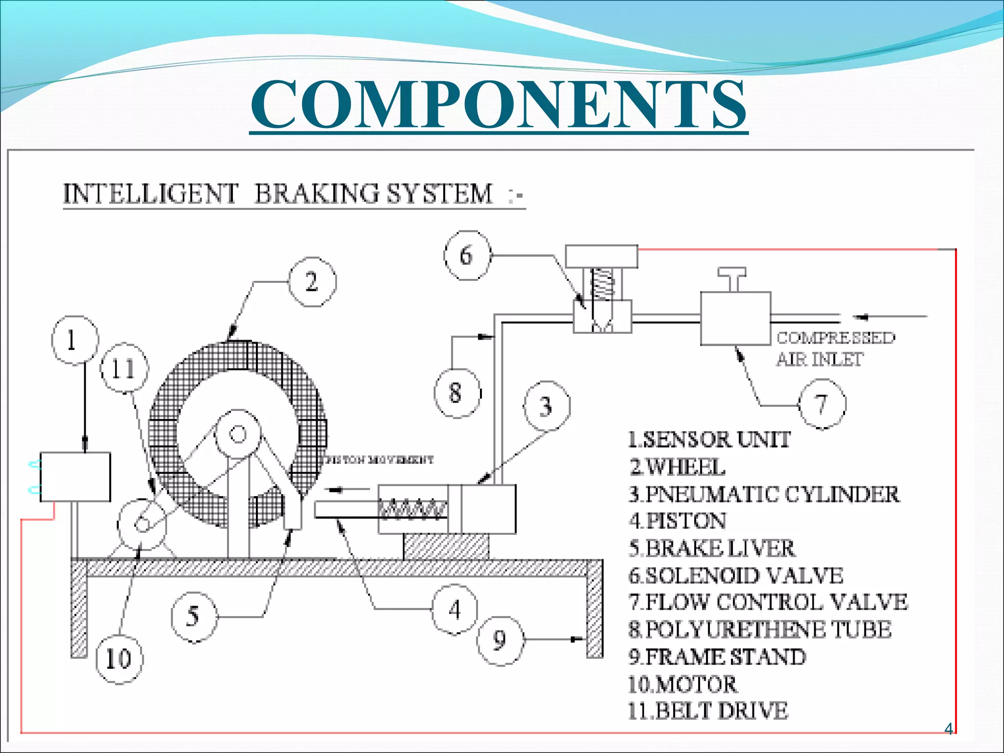
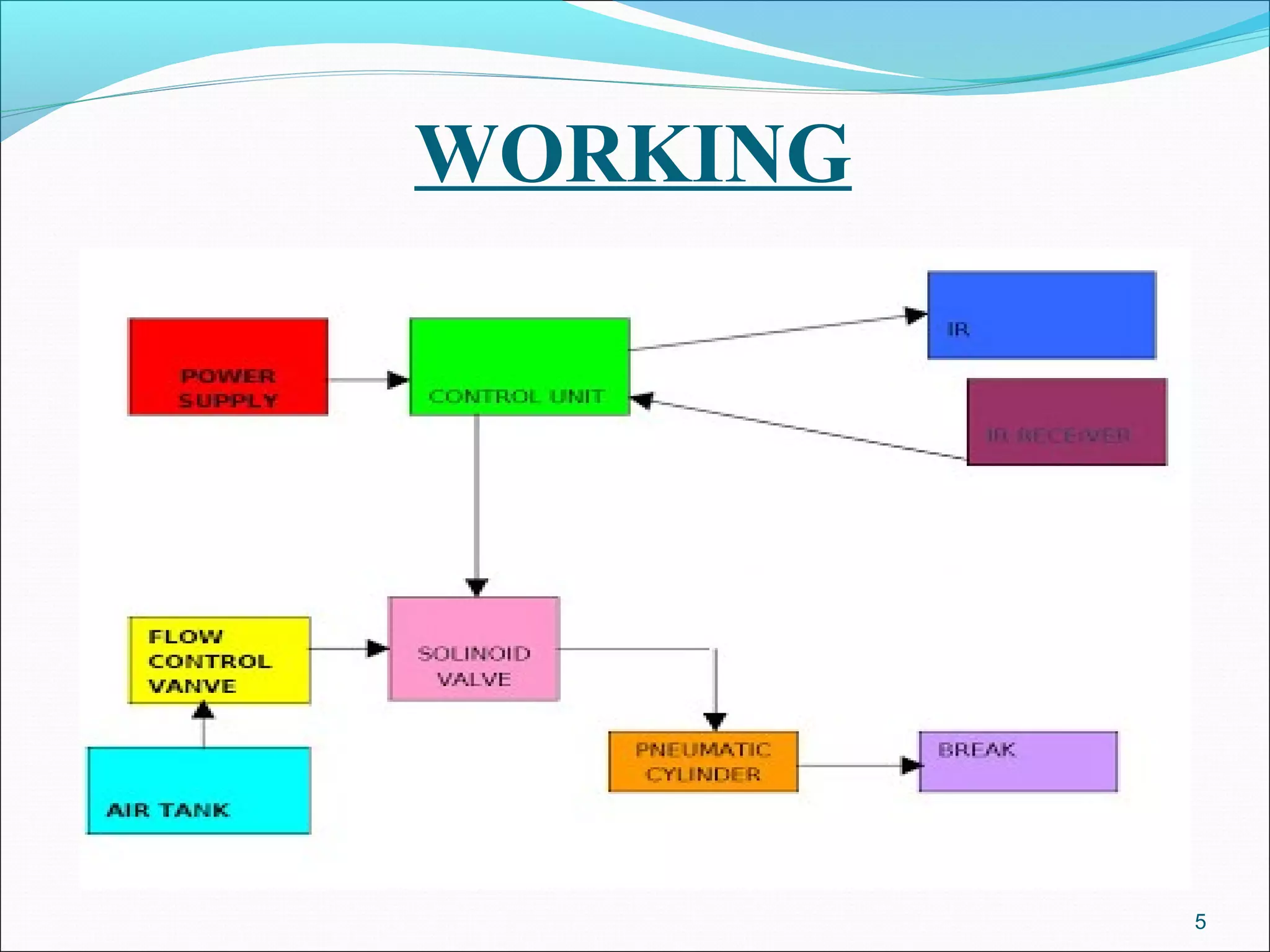
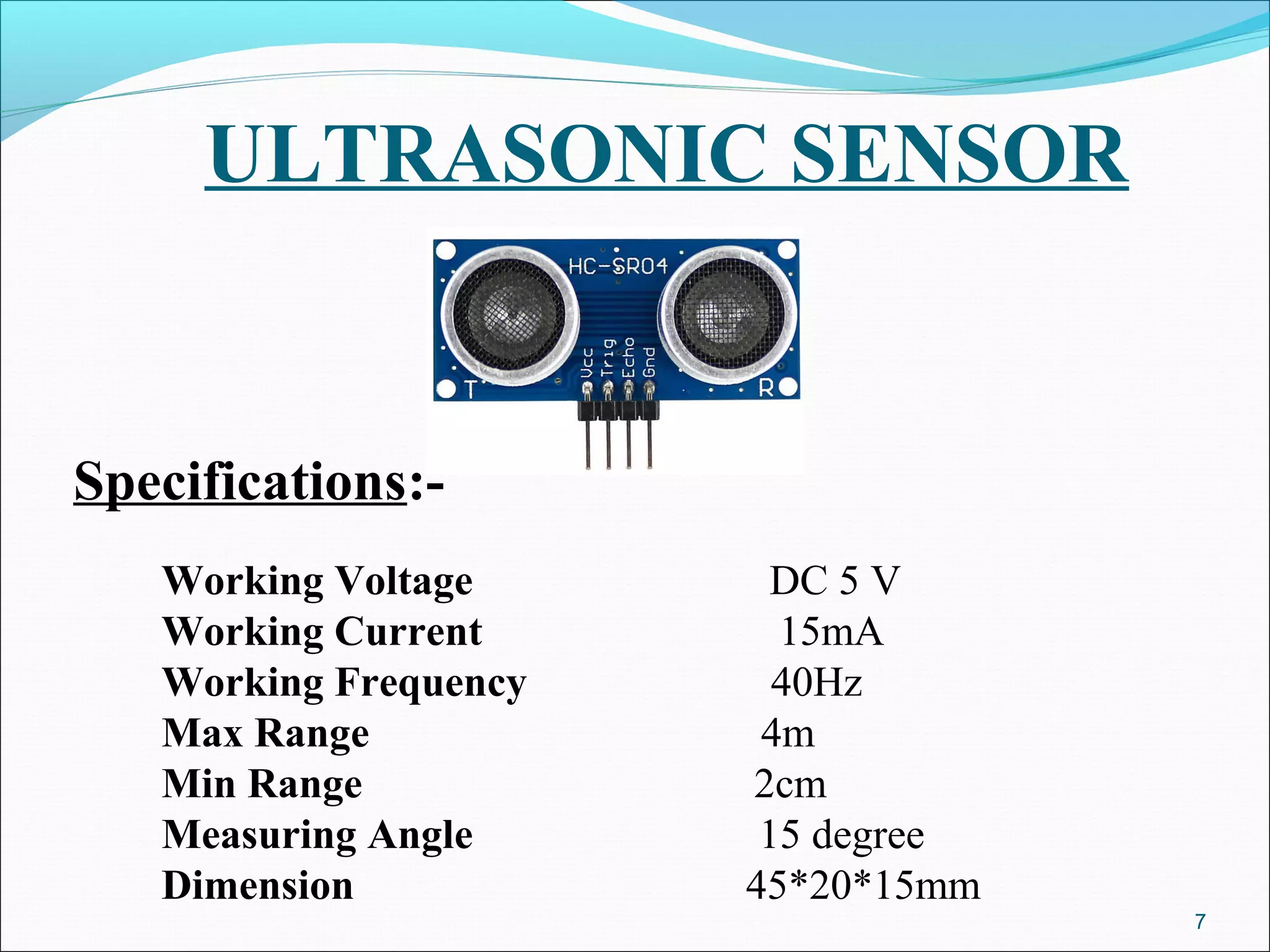
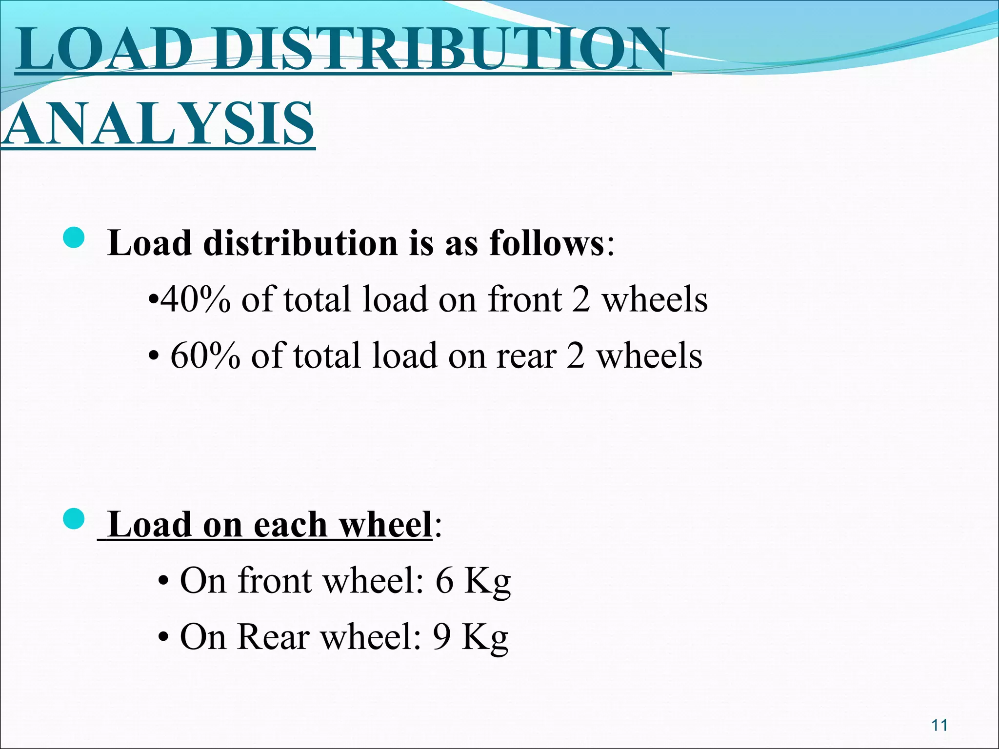
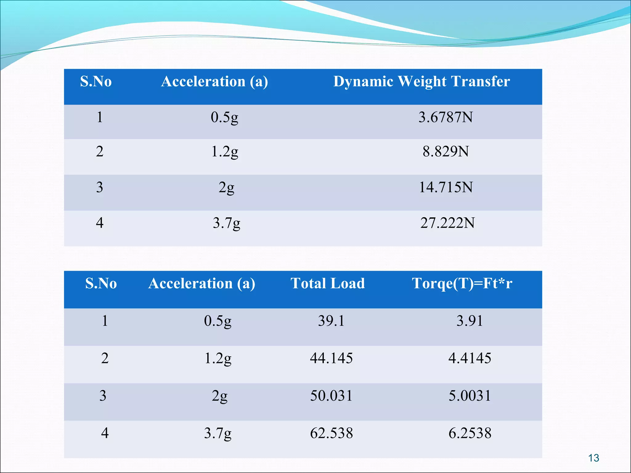
INTELLIGENT BRAKINGINTELLIGENT BRAKING
SYSTEMSYSTEM
Dr. MS NarwalDr. MS Narwal
Associate ProfessorAssociate Professor
MED DCRUST MurthalMED DCRUST Murthal
Submitted By:-Submitted By:-
Ankit (Ankit (1400100400714001004007))
Pardeep Kumar (14001004026)Pardeep Kumar (14001004026)
Rakesh (Rakesh (1400100403514001004035))
Sanjay (Sanjay (1400100404814001004048))
Pawan (Pawan (1500100491115001004911))
1
CONTENTS
Introduction
Components
Working
Design & Calculations
Conclusion
Advantages
Application
2
INTRODUCTION
Need of Automatic Reverse Braking System
Automatically operated pneumatic braking system
Fully Automated braking
Beneficial to Customers
3
COMPONENTS
4
WORKING
5
COMPONENTS
1. ULTRASONIC SENSOR
2. SOLENOID VALVE
3. DC MOTOR
4. SINGLE ACTING PNEUMATIC CYLINDER
5. PNEUMATIC BRAKING SYSTEM
6. TYRES
7. CHASIS & BODY
6
ULTRASONIC SENSOR
Specifications:-
Working Voltage DC 5 V
Working Current 15mA
Working Frequency 40Hz
Max Range 4m
Min Range 2cm
Measuring Angle 15 degree
Dimension 45*20*15mm
7
SOLENOID VALVE
Working Medium Air, Inert Gas, & Liquid
Operating Temperature -5 to 80°C
Body Material Nylon, Engineered Plastic
Plunger & Spring Stainless Steel
Specifications:-
8
9
MATHEMATICAL
MODELING
Weight of vehicle : 30 kg
Frictional coefficient of wheel : 0.6
Frictional coefficient between disc & cylinder : 1.5
Wheel base: 0.9 Meter
C.G. of vehicle from ground: 0.15 meter.
Dia. of tyre : 0.2 m
Inner diameter of disc (Di): 50 mm
Outer dia of disc (Do): 100 mm
10
LOAD DISTRIBUTION
ANALYSIS
 Load distribution is as follows:
•40% of total load on front 2 wheels
• 60% of total load on rear 2 wheels
 Load on each wheel:
• On front wheel: 6 Kg
• On Rear wheel: 9 Kg
11
Static load on wheel
Fs = µf× Rn
= 0.6 × 6 × 9.81
Fs = 35.316
Dynamic weight transfer
Fd =(m × a × h)/w
=(9×0.5×9.81×0.15)/(2×0.9)
{For a = 0.5 g}
= 3.6787 N
Total load (FT)
= Fs + Fd
=39.1N 12
S.No Acceleration (a) Dynamic Weight Transfer
1 0.5g 3.6787N
2 1.2g 8.829N
3 2g 14.715N
4 3.7g 27.222N
S.No Acceleration (a) Total Load Torqe(T)=Ft*r
1 0.5g 39.1 3.91
2 1.2g 44.145 4.4145
3 2g 50.031 5.0031
4 3.7g 62.538 6.2538
13
Clamp Load C = Torque/(µf × Re × n)
{ Where Re =(Ri + Ro)/2
=(25 + 50)/2
=37.5 mm }
=(3.91)/(1.5 ∗0.0375 2∗ )
= 34.75 N
S.No Acceleration (a) Clamp Load
1 0.5g 34.75N
2 1.2g 39.24N
3 2g 44.47N
4 3.7g 55.58N
14
Dist.
Speed
S=10m S=8m S=6m S=4m
Calculations of required deceleration rate for various
allowable distances:-
15
CONCLUSION
The whole system works only while reversing the
vehicle.When sensor senses any obstacle behind the
vehicle,its sends the signal to the control unit(solenoid
valve and flow control valve) which allows the passage
of air from the compressor to the pneumatic cylinder
which push the piston forward and just stopping the
running wheel.Thus we have an “INTELLIGENT
BRAKING SYSTEM”” which helps in understanding
how to achieve low cost automation.
16
ADVANTAGES
Less operating force is required.
Greater safety in Reverse braking.
Automated operation.
Can be used in running as well as parking mode.
17
APPLICATIONS
In Automatic Parking of car developed
by Volvo
Used in cars,trucks
18
THANK YOU
19

INTELLIGENT BRAKING SYSTEM

  • 1.
    INTELLIGENT BRAKINGINTELLIGENT BRAKING SYSTEMSYSTEM Dr.MS NarwalDr. MS Narwal Associate ProfessorAssociate Professor MED DCRUST MurthalMED DCRUST Murthal Submitted By:-Submitted By:- Ankit (Ankit (1400100400714001004007)) Pardeep Kumar (14001004026)Pardeep Kumar (14001004026) Rakesh (Rakesh (1400100403514001004035)) Sanjay (Sanjay (1400100404814001004048)) Pawan (Pawan (1500100491115001004911)) 1
  • 2.
  • 3.
    INTRODUCTION Need of AutomaticReverse Braking System Automatically operated pneumatic braking system Fully Automated braking Beneficial to Customers 3
  • 4.
  • 5.
  • 6.
    COMPONENTS 1. ULTRASONIC SENSOR 2.SOLENOID VALVE 3. DC MOTOR 4. SINGLE ACTING PNEUMATIC CYLINDER 5. PNEUMATIC BRAKING SYSTEM 6. TYRES 7. CHASIS & BODY 6
  • 7.
    ULTRASONIC SENSOR Specifications:- Working VoltageDC 5 V Working Current 15mA Working Frequency 40Hz Max Range 4m Min Range 2cm Measuring Angle 15 degree Dimension 45*20*15mm 7
  • 8.
    SOLENOID VALVE Working MediumAir, Inert Gas, & Liquid Operating Temperature -5 to 80°C Body Material Nylon, Engineered Plastic Plunger & Spring Stainless Steel Specifications:- 8
  • 9.
  • 10.
    MATHEMATICAL MODELING Weight of vehicle: 30 kg Frictional coefficient of wheel : 0.6 Frictional coefficient between disc & cylinder : 1.5 Wheel base: 0.9 Meter C.G. of vehicle from ground: 0.15 meter. Dia. of tyre : 0.2 m Inner diameter of disc (Di): 50 mm Outer dia of disc (Do): 100 mm 10
  • 11.
    LOAD DISTRIBUTION ANALYSIS  Loaddistribution is as follows: •40% of total load on front 2 wheels • 60% of total load on rear 2 wheels  Load on each wheel: • On front wheel: 6 Kg • On Rear wheel: 9 Kg 11
  • 12.
    Static load onwheel Fs = µf× Rn = 0.6 × 6 × 9.81 Fs = 35.316 Dynamic weight transfer Fd =(m × a × h)/w =(9×0.5×9.81×0.15)/(2×0.9) {For a = 0.5 g} = 3.6787 N Total load (FT) = Fs + Fd =39.1N 12
  • 13.
    S.No Acceleration (a)Dynamic Weight Transfer 1 0.5g 3.6787N 2 1.2g 8.829N 3 2g 14.715N 4 3.7g 27.222N S.No Acceleration (a) Total Load Torqe(T)=Ft*r 1 0.5g 39.1 3.91 2 1.2g 44.145 4.4145 3 2g 50.031 5.0031 4 3.7g 62.538 6.2538 13
  • 14.
    Clamp Load C= Torque/(µf × Re × n) { Where Re =(Ri + Ro)/2 =(25 + 50)/2 =37.5 mm } =(3.91)/(1.5 ∗0.0375 2∗ ) = 34.75 N S.No Acceleration (a) Clamp Load 1 0.5g 34.75N 2 1.2g 39.24N 3 2g 44.47N 4 3.7g 55.58N 14
  • 15.
    Dist. Speed S=10m S=8m S=6mS=4m Calculations of required deceleration rate for various allowable distances:- 15
  • 16.
    CONCLUSION The whole systemworks only while reversing the vehicle.When sensor senses any obstacle behind the vehicle,its sends the signal to the control unit(solenoid valve and flow control valve) which allows the passage of air from the compressor to the pneumatic cylinder which push the piston forward and just stopping the running wheel.Thus we have an “INTELLIGENT BRAKING SYSTEM”” which helps in understanding how to achieve low cost automation. 16
  • 17.
    ADVANTAGES Less operating forceis required. Greater safety in Reverse braking. Automated operation. Can be used in running as well as parking mode. 17
  • 18.
    APPLICATIONS In Automatic Parkingof car developed by Volvo Used in cars,trucks 18
  • 19.