Download to read offline

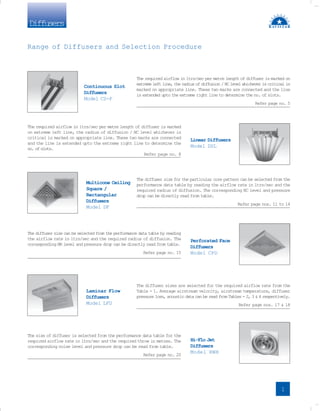
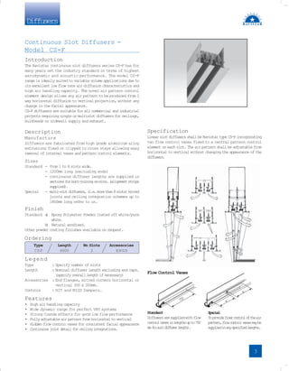
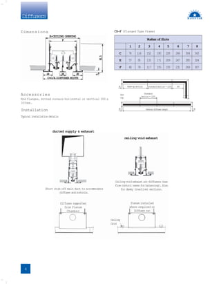
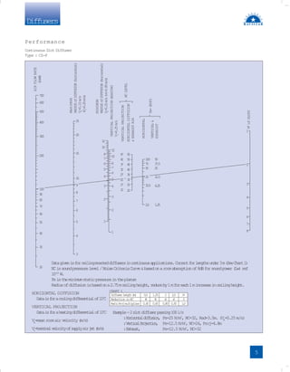
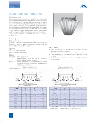
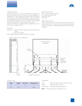
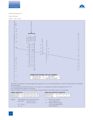
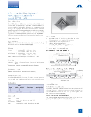
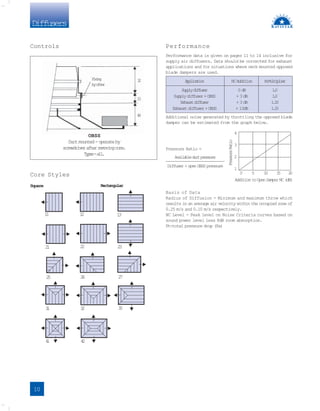
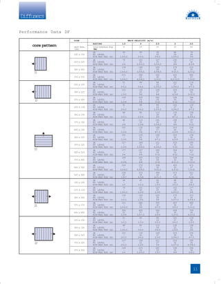
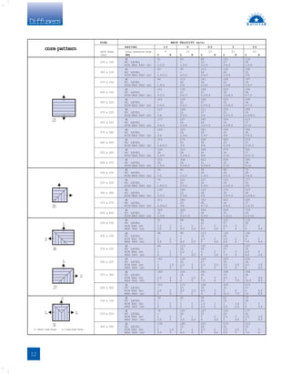
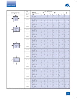
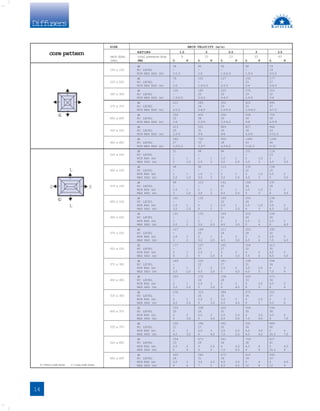
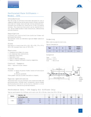
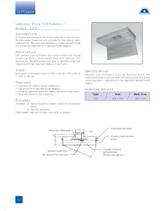
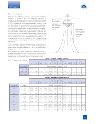
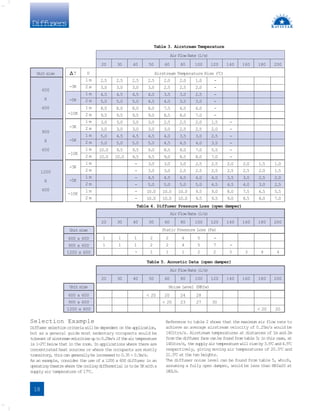
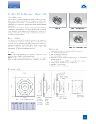
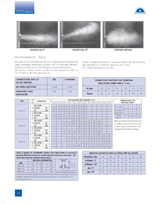
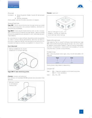
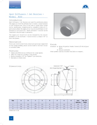
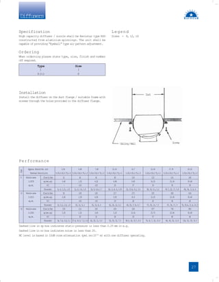
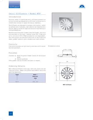
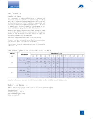
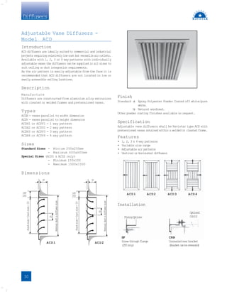


This document provides information on selecting and installing various types of diffusers, including: - Continuous slot diffusers that can adjust air pattern without changing appearance and are suitable for variable volume applications. Performance data is provided in a table. - Linear diffusers that are selected using performance data tables providing airflow, radius of diffusion, noise, and pressure drop. - Multicone ceiling diffusers where the size is selected from tables with airflow and radius of diffusion, with corresponding noise and pressure drop. - Details on other diffuser types like perforated face, laminar flow, jet, circular, spot, swirl, adjustable vane, and exhaust valves are provided with references to specific performance tables and sections