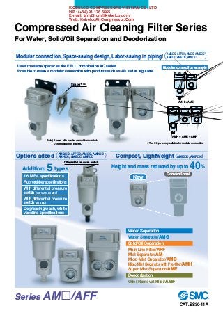
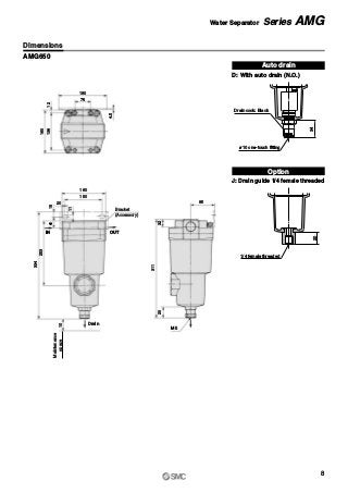
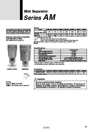
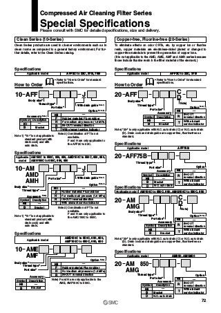
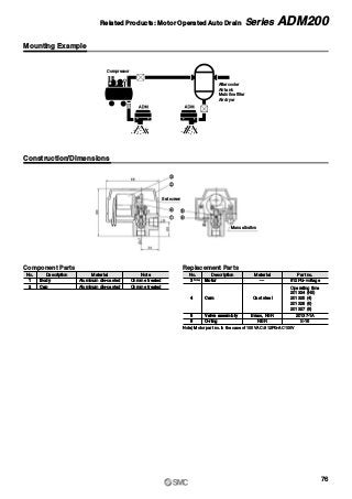
![Water Separator
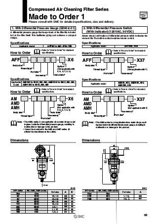
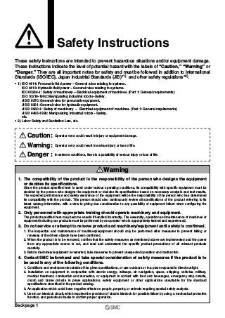
Water droplet
separation rate: 99%
Nominal filtration rating: 3 μm
[Filtration efficiency:
99%]
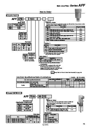
Main Line Filter
Mist Separator
Micro Mist Separator
Nominal filtration rating: 0.3 μm
[Filtration efficiency: 99.9%]
Oil mist density at outlet:
Max. 1.0 mg/m3 (ANR)
[≈0.8 ppm]
Nominal filtration rating: 0.01 μm
[Filtration efficiency: 99.9%]
Oil mist density at outlet:
Max. 0.1 mg/m3 (ANR)
[≈0.08 ppm]
Water droplet removalWater droplet removal
Large dust particle filtration, Oil droplet separationLarge dust particle filtration, Oil droplet separation
Dust filtration, Oil mist separationDust filtration, Oil mist separation
Dust filtration, Oil mist separationDust filtration, Oil mist separation
Model
AMG
AFF
AM
AMD
300
750
1,500
2,200
3,700
6,000
12,000
300
750
1,500
2,200
3,700
6,000
12,000
22,000
28,000
42,000
300
750
1,500
2,200
3,700
6,000
12,000
200
500
1,000
2,000
3,700
6,000
12,000
8,000
24,000
8,000
24,000
40,000
1/8, 1/4
1/4, 3/8
3/8, 1/2
1/2, 3/4
3/4, 1
1, 1 1/2
1 1/2, 2
1/8, 1/4
1/4, 3/8
3/8, 1/2
1/2, 3/4
3/4, 1
1, 1 1/2
1 1/2, 2
50(2B) flange
80(3B) flange
100(4B) flange
1/8, 1/4
1/4, 3/8
3/8, 1/2
1/2, 3/4
3/4, 1
1, 1 1/2
1 1/2, 2
1/8, 1/4
1/4, 3/8
3/8, 1/2
1/2, 3/4
3/4, 1
1, 1 1/2
1 1/2, 2
50(2B) flange
50(2B), 80(3B), 100(4B) flange
50(2B) flange
50(2B), 80(3B), 100(4B) flange
100(4B), 150(6B) flange
Flow capacity
l/min (ANR)
Max. flow
capacity at
0.7 MPa
inlet pressure
Port size Note
Piping
support
type
Piping
support
type
Free
standing
type
Free
standing
type
Piping
support
type
Piping
support
type
150C
250C
350C
450C
550C
650
850
2C
4C
8C
11C
22C
37B
75B
75A
125A
150A
220A
150C
250C
350C
450C
550C
650
850
150C
250C
350C
450C
550C
650
850
801
901
800
900
1000
AMG150C to 550C
AFF2C to 22C
AM150C to 550C
AMD150C to 550C AMD650 to 1000
AM650/850
AFF75A to 220AAFF37B/75B
AMG650/850
Features 1](https://image.slidesharecdn.com/compressedaircleaningfilterseriesamaffsmall-200505074046/85/Compressed-air-cleaning-filter-series-am-aff-small-2-320.jpg?cb=1715333324)
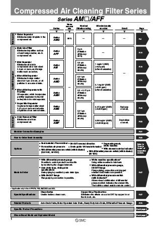
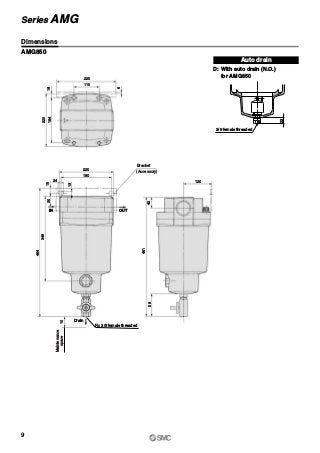
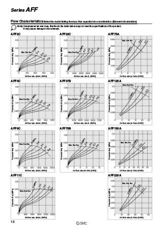
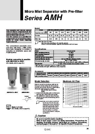
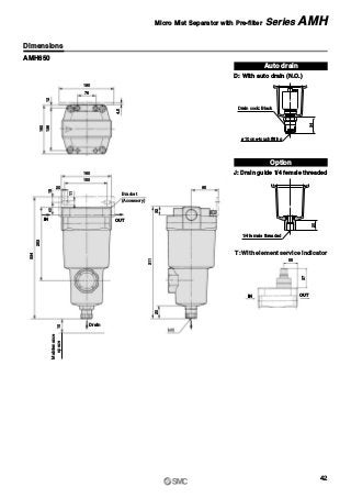
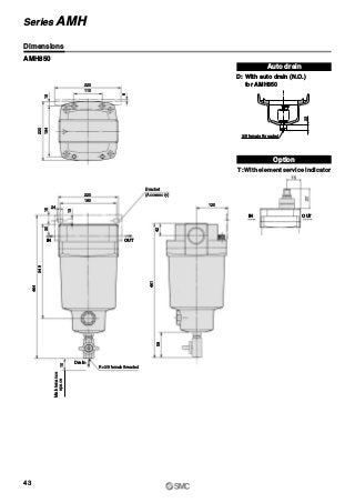
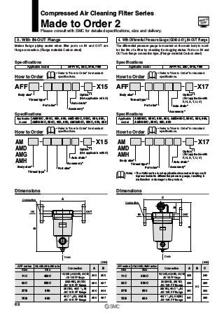
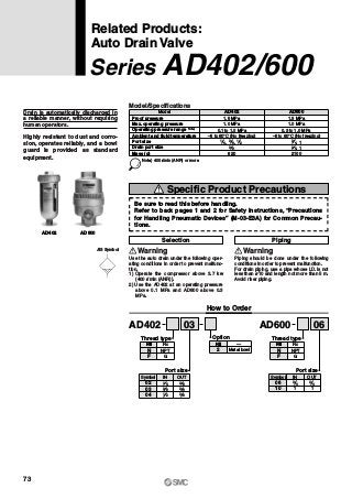
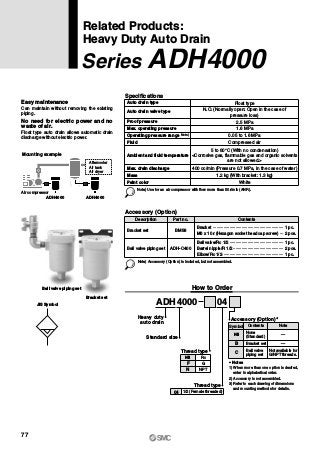
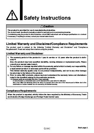
![Micro Mist Separator
with Pre-filter
Super Mist Separator
Odor Removal Filter
Built-in 0.3 μm pre-filter
The AM + AMD element have been integrated to
achieve a space-saving design.
Nominal filtration rating: 0.01 μm
[Filtration efficiency: 99.9%]
Oil mist density at outlet:
Max. 0.1 mg/m3 (ANR)
[≈0.08 ppm]
Color change indicates when element is saturated.
Nominal filtration rating: 0.01 μm
[Filtration efficiency: 99.9%]
Oil mist density at outlet:
Max. 0.01 mg/m3 (ANR)
[≈0.008 ppm]
Cleanliness at outlet:
Not more than 35
particles of size
0.3 μm or larger/10 l
(100 particles or less/ft3)
Nominal filtration rating: 0.01 μm
[Filtration efficiency: 99.9%]
Oil mist density at outlet:
Max. 0.004 mg/m3 (ANR)
[≈0.0032 ppm]
Dust filtration, Oil mist separationDust filtration, Oil mist separation
Dust filtration, Oil mist adsorptionDust filtration, Oil mist adsorption
DeodorizationDeodorization
Model
AMH
AME
AMF
200
500
1,000
2,000
3,700
6,000
12,000
200
500
1,000
2,000
3,700
6,000
12,000
200
500
1,000
2,000
3,700
6,000
12,000
8,000
24,000
8,000
24,000
40,000
1/8, 1/4
1/4, 3/8
3/8, 1/2
1/2, 3/4
3/4, 1
1, 1 1/2
1 1/2, 2
1/8, 1/4
1/4, 3/8
3/8, 1/2
1/2, 3/4
3/4, 1
1, 1 1/2
1 1/2, 2
1/8, 1/4
1/4, 3/8
3/8, 1/2
1/2, 3/4
3/4, 1
1, 1 1/2
1 1/2, 2
50(2B) flange
50(2B), 80(3B)
100(4B) flange
50(2B) flange
50(2B), 80(3B)
100(4B) flange
100(4B), 150(6B)
flange
Flow capacity
l/min (ANR)
Max. flow
capacity at
0.7 MPa
inlet pressure
Port size Note
Piping
support
type
Piping
support
type
Piping
support
type
Free
standing
type
150C
250C
350C
450C
550C
650
850
150C
250C
350C
450C
550C
650
850
150C
250C
350C
450C
550C
650
850
801
901
800
900
1000
AMH150C to 550C AMH650/850
AME150C to 550C AME650/850
AMF150C to 550C AMF650 to 1000
Features 2
Series AM„/AFF](https://image.slidesharecdn.com/compressedaircleaningfilterseriesamaffsmall-200505074046/85/Compressed-air-cleaning-filter-series-am-aff-small-3-320.jpg?cb=1715333324)
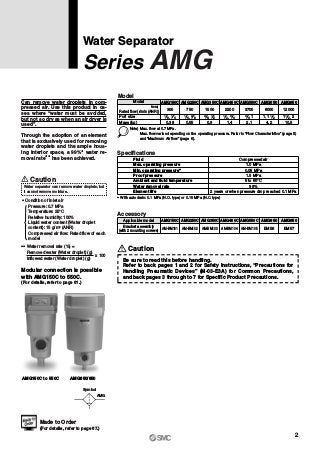
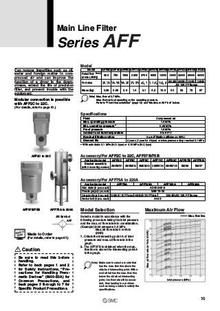
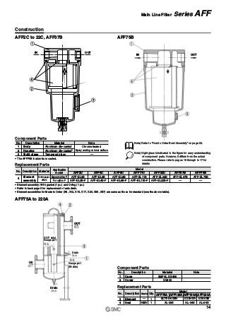
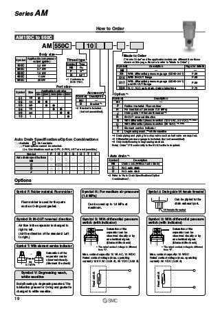

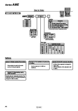
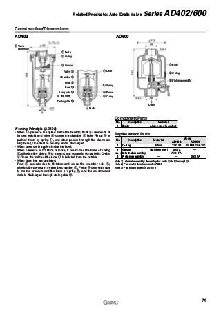
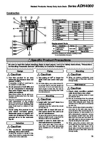
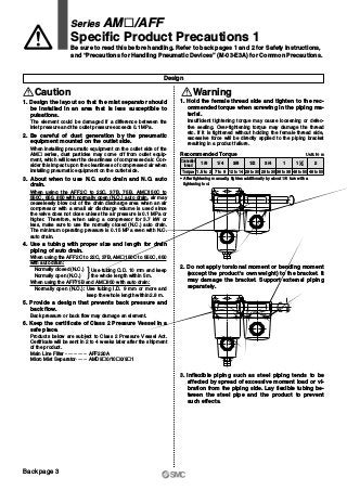
![Symbol
AME
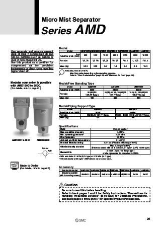
Can separate and adsorb aerosol
state fine oil particles in com-
pressed air and change the oil lubri-
cating compressed air to oilless air
or equivalent.
Use this product for filtration of
compressed air requiring higher
clean air for painting lines, com-
pressed air for clean rooms and/or
equipment where oils must be avoi-
ded.
Indicates the filter element life
by a color change. Accordingly,
the replacement time can be
judged visually. (A red color spot in-
dicates the replacement time.)
Model
Port size
Mass (kg)
Model
200
AME150C
500
AME250C
1000
AME350C
2000
AME450C
3700
AME550C
6000
AME650
12000
0.3 0.48 0.8 1.3 2.0 4.2 10.5
AME850
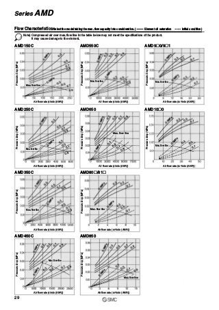
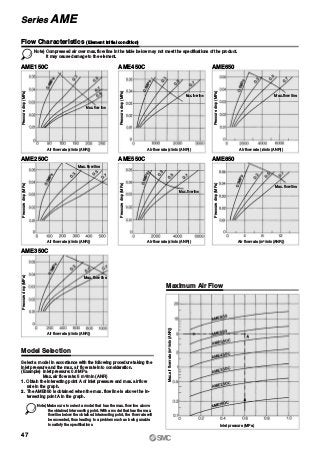
Note) Max. flow at 0.7 MPa.
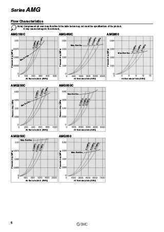
Max. flow varies depending on the operating pressure.
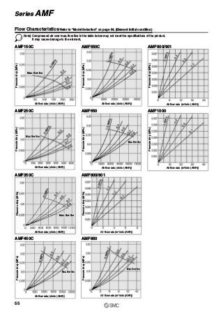
Refer to “Flow Characteristics” (page 47) and “Maximum Air Flow” (page 47).
1 8, 1 4 1 4, 3 8 3 8, 1 2 1 2, 3 4 13 4,
Specifications
0.05 MPa
1.5 MPa
Compressed air
1.0 MPa
5 to 60°C
0.01 μm (Filtration efficiency: 99.9%)
Less than 100 particles of 0.3 μm or larger per cubic foot
[Less than 35 particles per 10 liters (ANR)]
Fluid
Max. operating pressure
Min. operating pressure
Proof pressure
Ambient and fluid temperature
Nominal filtration rating
Element life
Cleanliness at outlet
Oil mist density at outlet
Max. 0.01 mg/m3
(ANR)
(≈0.008 ppm)
Element color indicator (Replace the element when a red color
spot occurred on the surface.)
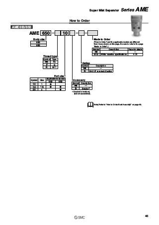
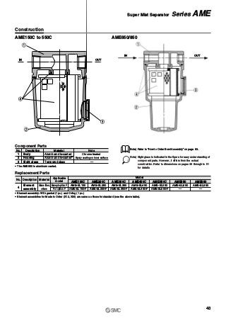
Super Mist Separator
Series AME
Accessory
AME150C AME250C AME350C AME450C AME550C AME650 AME850
AM-BM101 AM-BM102 AM-BM103 AM-BM104 AM-BM105 BM56 BM57
Applicable model
Bracket assembly
(with 2 mounting screws)
Caution
By all means the “AM” series
should be used as a pre-filter.
Modular connection is possible
with AME150C to 550C.
(For details, refer to page 61.)
AME150C to 350C AME450C/550C
AME650/850
11, 1 2 1 21 2,
Rated flow (l/min (ANR))
Note)
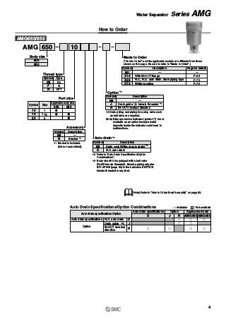
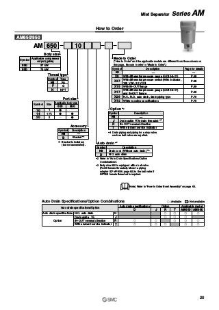
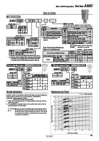
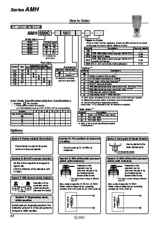
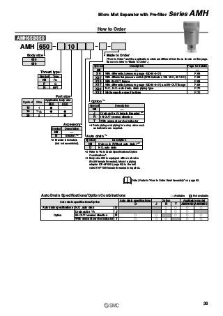
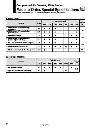
Made to Order
(For details, refer to page 67.)
Caution
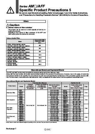
Be sure to read this before handling.
Refer to back pages 1 and 2 for Safety Instructions, “Precautions for
Handling Pneumatic Devices” (M-03-E3A) for Common Precautions,
and back pages 3 through to 7 for Specific Product Precautions.
44](https://image.slidesharecdn.com/compressedaircleaningfilterseriesamaffsmall-200505074046/85/Compressed-air-cleaning-filter-series-am-aff-small-46-320.jpg?cb=1715333324)

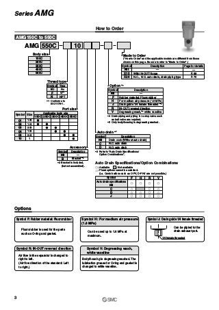
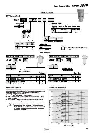
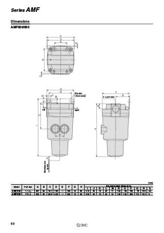
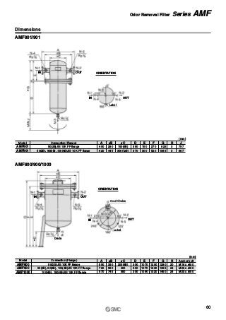
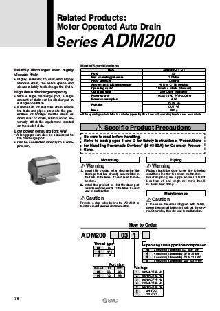
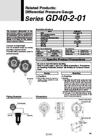
![Symbol
AMF
Odor Removal Filter
Series AMF
Efficiently can remove odor in com-
pressed air with an activated carbon
element. The unit is designed for
use in the area such as a clean
room where odors must be avoided.
Can remove odor and gas ingre-
dients in compressed air.
Activated carbon element with large
filtration area.
Easy replacement of elements.
Accessory (Option)
Model
1 8, 1 4 1 4, 3 8 3 8, 1 2 1 2, 3 4Port size
Mass (kg)
Model
200
AMF150C
500
AMF250C
1000
AMF350C
2000
AMF450C
3700
AMF550C
6000
AMF650
12000
0.3 0.48 0.8 1.3 2.0 4.2 10.5
AMF850
Note) Max. flow at 0.7 MPa.
Max. flow varies depending on the operating pressure.
Refer to “Flow Characteristics” (page 55) and “Maximum Air Flow” (page 54).
13 4,
Model/Free Standing Type
Rated flow (l/min (ANR))
Model
8000
AMF800
24000
AMF900
40000
Port size
50(2B)JIS
10K FF flange
50(2B), 80(3B),100(4B)JIS
10K FF flange
100(4B),150(6B)JIS
10K FF flange
Mass (kg) 90 200 410
AMF1000
Model/Piping Support Type
Rated flow (l/min (ANR))
Model
8000
AMF801
Port size 50(2B)JIS 10K FF flange
Mass (kg) 40
24000
AMF901
50(2B), 80(3B),100(4B)JIS 10K FF flange
120
Specifications
Fluid
Max. operating pressure
Min. operating pressure
Proof pressure
Ambient and fluid temperature
Nominal filtration rating
Cleanliness at outlet
Oil mist density at outlet
0.05 MPa
1.5 MPa
Compressed air
1.0 MPa
5 to 60°C
0.01 μm (Filtration efficiency: 99.9%)
Less than 100 particles of 0.3 μm or larger per cubic foot
[Less than 35 particles per 10 liters (ANR)]
(The “AME” series is required on the inlet side.)
Max. 0.004 mg/m3
(ANR) (≈0.0032 ppm)
(The “AME” series is required on the inlet side.)
AMF150C AMF250C AMF350C AMF450C AMF550C AMF650 AMF850
AM-BM101 AM-BM102 AM-BM103 AM-BM104 AM-BM105 BM56 BM57
Applicable model
Bracket assembly
(with 2 mounting screws)
Modular connection is possible
with AMF150C to 550C.
(For details, refer to page 61.)
AMF150C to 350C AMF450C/550C
AMF650/850
11, 1 2 1 21 2,
Rated flow (l/min (ANR))
Note)
Made to Order
(For details, refer to page 67.)
Caution
Be sure to read this before handling.
Refer to back pages 1 and 2 for Safety Instructions, “Precautions for
Handling Pneumatic Devices” (M-03-E3A) for Common Precautions,
and back pages 3 through to 7 for Specific Product Precautions.
52](https://image.slidesharecdn.com/compressedaircleaningfilterseriesamaffsmall-200505074046/85/Compressed-air-cleaning-filter-series-am-aff-small-54-320.jpg?cb=1715333324)


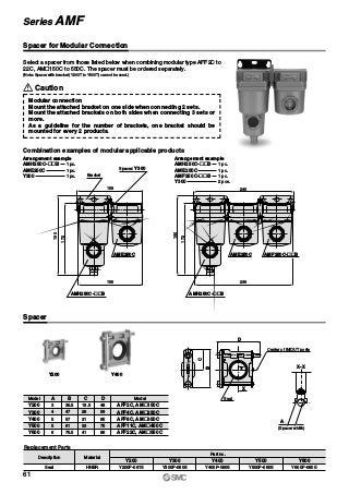

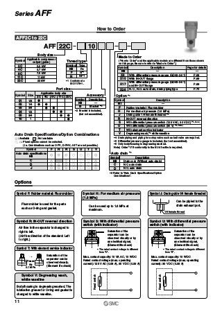
![Option: Reference Figure of Assembly
Piping example of ball valve piping set
(54)
(45) (41)
(100)
Bracket (Option)
120
100
200
8
7
10
30
16155
Model no. label
Caution label
(Maintenancespace)
108
100
58 33
M6 Hexagon socket head cap screw
[Applicable hexagon wrench key nominal size 5]
M6 Hexagon socket head cap screw
[Applicable hexagon wrench key nominal size 5]
100
Flushing buttonBleed valve
(Refer to “Maintenance” 4.)
Pilot exhaust port
Bracket mounting hole
(Both sides)
Drain inlet 1/2 female threaded
(Refer to “How to Order” for type of thread.)
171
(176)
189
Octagonal width
across flats 30
Hexagon width across flats 27
Drain outlet 1/2 female threaded
(Refer to “How to Order” for type of thread.)
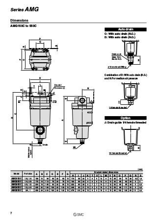
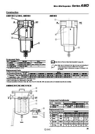
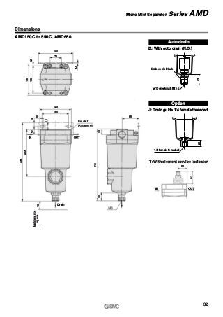
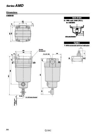
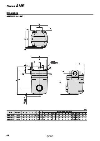
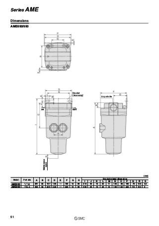
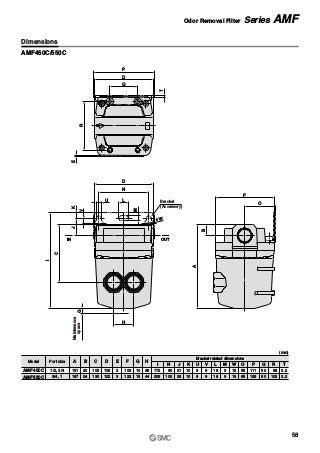
Dimensions
79
Series ADH4000](https://image.slidesharecdn.com/compressedaircleaningfilterseriesamaffsmall-200505074046/85/Compressed-air-cleaning-filter-series-am-aff-small-81-320.jpg?cb=1715333324)
![IN
OUT
Symbol which indicates the flow of
compressed air
or
Caution
1. About the mounting orientation of the products
Make sure to install this product on horizontal piping. If it is in-
stalled diagonally, laterally, or upside down, the drain separa-
ted by the element will splash to the outlet side.
Mounting
Selection
Caution
1. About the system composition of purifying com-
pressed air
Compressed air generally contains particulate contaminants
as listed below, though there are some variations due to the
compressor type and specifications. Determine the system
configuration according to the desired cleanliness of com-
pressed air and application, while referring to the “Air Prepara-
tion Equipment Selection Guide” for the AM„ series (Best
Pneumatics).
[Particulate contaminants in compressed air]
• Water (drainage)
• Dust sucked from ambient air
• Degenerated oil from compressor
• Solid foreign matter such as rust inside piping and oil
2. Select according to the maximum flow consump-
tion.
When compressed air is used for air blow, etc., find the maxi-
mum air consumption before selecting the size of the AM„
series. (If compressed air exceeding the maximum flow rate is
supplied, it can result in decline of the cleanliness of com-
pressed air or element damage.)
Caution
Piping
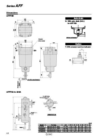
In the case of the AFF75A to 220A, AMD801, 901, 800, 900,
1000
INLET and OUTLET of compressed air is labeled on the side
of flange. Be sure to connect correctly.
2. Use an air blower to flush the piping before con-
necting the piping.
Use an air blower to thoroughly flush the piping, or wash the
piping to remove any cutting chips, cutting oil, or debris from
inside the piping before connecting them.
3. Wrapping of sealant tape
When screwing in the pipes or fittings, make sure to prevent
cutting chips or the sealant material on the threaded portion of
the pipe from entering the piping. If sealant tape is to be used,
leave about 1.5 to 2 ridges of threads uncovered.
4. Modular connection
Mount the attached bracket on one side when connecting 2
sets. Mount the attached brackets on both sides when con-
necting 3 sets or more. As a guideline for the number of
brackets, one bracket should be mounted for every 2 prod-
ucts.
1. Connect it with IN and OUT ports in proper location.
It does not work with the connection reversed.
In the case of the AFF2C to 22C, 37B, 75B, AM„150C to
550C, 650, 850
Verify the direction of the flow of the compressed air and the
“ ” or “ ” mark that indicates the inlet of the product before
connecting. It cannot be used if connected in the opposite di-
rection.
Series AM„/AFF
Specific Product Precautions 2
Be sure to read this before handling. Refer to back pages 1 and 2 for Safety Instructions,
and “Precautions for Handling Pneumatic Devices” (M-03-E3A) for Common Precautions.
Back page 4](https://image.slidesharecdn.com/compressedaircleaningfilterseriesamaffsmall-200505074046/85/Compressed-air-cleaning-filter-series-am-aff-small-86-320.jpg?cb=1715333324)
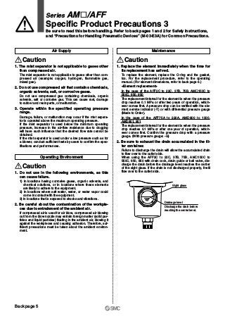
![Open Close
O S
øA
B
Others
Caution
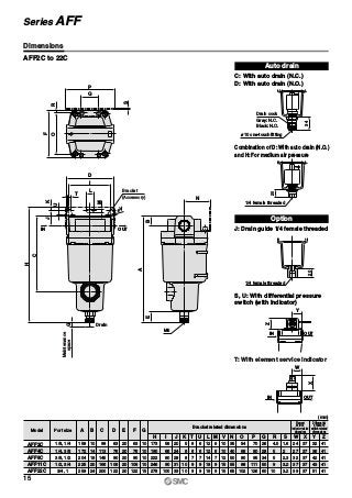
1. Element interchange
Following is the element dimensions for the AFF and AM„
series:
Since elements for the same body size has the same dimen-
sions, they are interchangeable.
However, do not interchange them easily since it can cause
various kinds of problems.
If interchanging the elements is unavoidable, replace the
product model number label, too.
2. About oil-free products
The AFF and AM„ series includes parts (such as resin parts,
rubber parts, and elements) that does not allow degreasing
wash. Therefore, oil-free products with all parts degreasing
washed is not available.
3. Degreasing wash
Certain parts such as the body and housing can be degreas-
ing washed. Contact SMC after confirming the specifications.
(available as Option or Made to Order)
4. Change of oil
On the AFF and AM„ series, no oil such as grease is applied
to parts exposed to compressed air. However, for certain
specifications, there are some parts to which oil is applied.
It is possible to change the type of applied oil (as Option or
Made to Order).
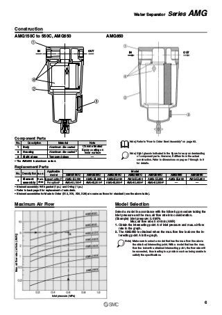
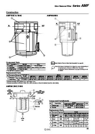
Element Dimensions
Model
Element dimensions
(Reference value)
øA B
AFF2C, AFF2B, AM150C, AM150
AMD150C, AMD150, AMH150C, AMH150
AFF4C, AFF4B, AM250C, AM250
AMD250C, AMD250, AMH250C, AMH250
AFF8C, AFF8B, AM350C, AM350
AMD350C, AMD350, AMH350C, AMH350
AFF11C, AFF11B, AM450C, AM450
AMD450C, AMD450, AMH450C, AMH450
AFF22C, AFF22B, AM550C, AM550
AMD550C, AMD550, AMH550C, AMH550
AFF37B, AM650
AMD650, AMH650
49
58
70
82
96
122
142
42
52
78
88
118
144
223
AFF75B, AM850
AMD850, AMH850
Maintenance
Caution
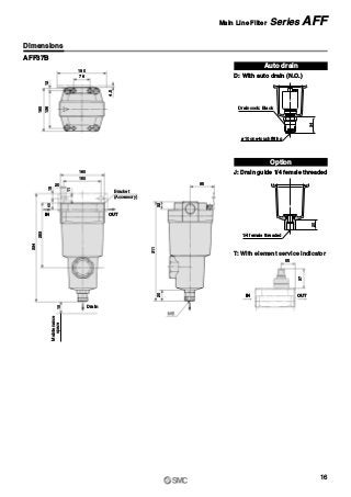
3. In the case of a type with auto drain
• The auto drain operates when the drainage level reaches the
top of the sight glass, and the drain will be discharged.
• When using the AFF2C to 22C, 37B, AM„150C to 550C,
650 with auto drain, the drain is automatically discharged
with the knob tightened to the “S” side. Manual drain dis-
charge, however, is also possible.
<Manual operation>
A manual knob attached to the auto drain end is tightened to
the “S” side in normal operation. The drain can be discharged
by loosening it to the “O” side. (Be careful, however, if pres-
sure remains inside the filter when the drain is discharged, the
drain will blow out from the drain port.)
4. The drain exhaust parts replacement method and
necessary parts are different depending on when it
was manufactured.
Description
AM-SA003
AM-SA004
AD34PA-D Note)
AD43PA-D
AD53PA-D
AM-SA002
Necessary parts
Manufactured
Dec. 2002 or before
[Up to manufacturing
lot No. GZ]
Manufactured
Jan. 2003 onwards
[Manufacturing lot No.
HO onwards]
Applicable
size
2C to 22C
2B to 37B
150C to 550C
150 to 650
2C to 22C
2B to 22B
150C to 550C
150 to 550
75B, 850
Drain guide
Drain cock
Ball valve set
N.O. auto drain
N.O. auto drain
N.C. auto drain
Auto drains cannot be
replaced alone since
those cannot be
assembled without
dedicated assembly
tools. The entire bowl
assembly must be
replaced. (Refer to
“How to Order Bowl
Assembly” on page
63.)
Note) Jig (AM-SA005) for replacing auto drain is necessary for the 75B or 850.
Series AM„/AFF
Specific Product Precautions 4
Be sure to read this before handling. Refer to back pages 1 and 2 for Safety Instructions,
and “Precautions for Handling Pneumatic Devices” (M-03-E3A) for Common Precautions.
Back page 6](https://image.slidesharecdn.com/compressedaircleaningfilterseriesamaffsmall-200505074046/85/Compressed-air-cleaning-filter-series-am-aff-small-88-320.jpg?cb=1715333324)

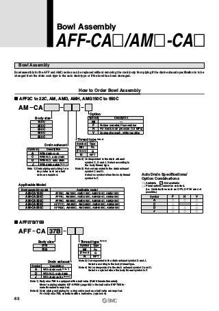
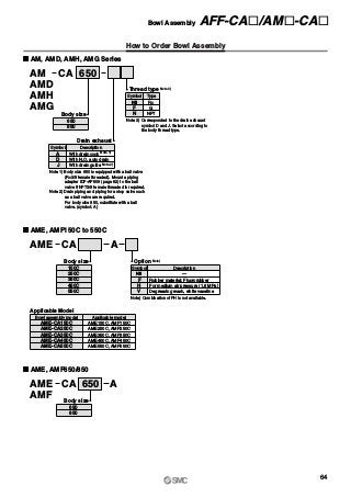
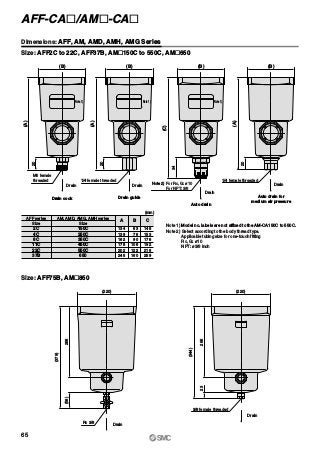
The document outlines various models of compressed air cleaning filters, water separators, and mist separators, detailing their specifications, performance ratings, and modular connection possibilities. It highlights features such as high filtration efficiency and the capability to eliminate impurities like water droplets and oil mist in compressed air systems. Additionally, options for customization and specific operating instructions are provided for optimal usage in industrial applications.


