Download to read offline
![IJSRD - International Journal for Scientific Research & Development| Vol. 2, Issue 07, 2014 | ISSN (online): 2321-0613
All rights reserved by www.ijsrd.com 209
Analysis of Material Removal Rate of AISI 304 SS in EDM Process
Ved Prakash Pandey1
Mr. R.N.Mall2
1
PG Scholar 2
Assistant Professor
1,2
Department of Mechanical Engineering
1,2
Madan Mohan Malaviya University of Technology Gorakhpur
Abstract— EDM has become an important and cost-
effective method of machining extremely tough and brittle
electrically conductive materials. It is widely used in the
process of making moulds and dies and sections of complex
geometry and intricate shapes. The work piece material
selected in this experiment is AISI 304 Stainless steel taking
into account its wide usage in industrial applications. In
today’s world 304 stainless steel contributes to almost half
of the world’s production and consumption for industrial
purposes. The input variable parameters are current, pulse
on time and duty cycle. Taguchi method is applied to create
an L27 orthogonal array of input variables using the Design
of Experiments (DOE). The effect of the variable parameters
mentioned above upon machining characteristics such as
Material Removal Rate (MRR), Surface Roughness (SR)
and Overcut (OC) is studied and investigated. The tool
material is copper. The results obtained showed that current
was the most significant parameter followed by pulse on
time and the least significant was the duty cycle for the
entire three responses namely Material removal rate, Surface
roughness and overcut. With the increase in current and duty
cycle MRR increased but for pulse on time it increased only
up to 100 µs and then started to decrease. SR increased
significantly with the increase in current; for pulse on time it
increased up to 100 µs and after that there was no significant
increase; and in case of duty cycle SR increased up to 70%
and then started to decrease. OC increased with the increase
in current and pulse on time but in different fashion and in
case of duty cycle, OC increased up to 70% and then started
decreasing.
Keywords: MRR-Material Removal Rate, EDM-Electric
Discharge, Taguchi design in MINITAB
I. INTRODUCTION
Electrical discharge machining is a non-traditional
machining method. It is a process for eroding and removing
material from electrically conductive materials by use of
consecutive electric sparks. The process is carried out in a
dielectric liquid with a small gap between the work piece
and electrode. Each electrical discharge generates heat
energy in a narrow area that locally melts, evaporates and
even ionizes work piece material. EDM does not make
direct contact between the electrode and the work piece
where it can eliminate mechanical stresses, chatter and
vibration problems during machining. Some of the melted
and all of the evaporated material is then quenched and
flushed away by dielectric liquid and the remaining melt
recast on the finished surface[1]. Important Parameters of
EDM process are Spark on-time (Ton): The duration of time
(µs) the current is allowed to flow per cycle.
Spark off-time (Toff): the duration of time in
between the sparks generated. During this time the molten
material gets removed from the gap between the electrode
and the workpiece.
Voltage (V): It is the potential difference applied
between the electrode and the workpiece.
Discharge Current (Ip): It is the current flowing
through the electrode and is measured in amp.
Duty cycle: It is the ratio of Ton divided by total
cycle time (Ton+Toff)[2].
The quality of an EDM product is usually
evaluated in terms of its surface integrity, which is
characterized by the surface roughness, existence of surface
cracks and residual stresses. There are many process
variables that affect the surface integrity such as pulse
duration, peak current, open gap voltage, electrode polarity,
material properties of the tool electrode, work piece and
dielectric liquid, debris concentration and even size of the
electrode [1].
II. LITERATURE REVIEW
In this paper, some selected research papers have been
discussed related to Electrical Discharge Machining. The
studies carried out in these papers are mainly concerned
with the EDM parameters such as current, voltage, pulse on
time, duty cycle, etc. and how these affect the machining
characteristics like MRR, SR, OC, etc.B.S. Reddy et al.
carried out a study on the effect EDM parameters over
MRR, TWR, SR and hardness. Mixed factorial design of
experiments and multiple regression analysis techniques had
been employed to achieve the desired results. The
parameters in the decreasing order of importance for; MRR:
servo, duty cycle, current and voltage; TWR: current, servo
and duty cycle; SR: current; HRB: servo only. M.M.
Rahman et al. investigated the effect of the peak current and
pulse duration on the performance characteristics of the
EDM. The conclusions drawn were: the current and pulse on
time greatly affected the MRR, TWR and SR, the MRR
increases almost linearly with the increasing current, the SR
increases linearly with current for different pulse on time,
TWR increased with increasing peak current while
decreased when the pulse on time was increased. Puertas et
al. carried out results which showed that the intensity and
pulse time factor were the most important in case of SR
while the duty cycle factor was not significant at all. The
intensity factor was again influential in case of TWR. The
important factors in case of MRR were the intensity
followed by duty cycle and the pulse time. S.H. Tomadi et
al. investigated the machining of tungsten carbide with
copper tungsten as electrode. The full factorial design of
experiments was used for analyzing the parameters. In case
of SR, the important factors were voltage and pulse off time
while current and pulse on time were not significant. For
MRR the most influential was pulse on time followed by
voltage, current and pulse off time. Finally in case of TWR
the important factor was pulse off time followed by peak
current. Iqbal and Khan concluded that the voltage and
rotational speed of the electrode are the two significant](https://image.slidesharecdn.com/ijsrdv2i7108-150918091535-lva1-app6891/75/Anaysis-of-Material-Removal-Rate-of-AISI-304-SS-In-EDM-Process-1-2048.jpg)
![Analysis of Material Removal Rate of AISI 304 SS in EDM Process
(IJSRD/Vol. 2/Issue 07/2014/048)
All rights reserved by www.ijsrd.com 212
VII. CONCLUSION
In this study the experiment was conducted by considering
three variable parameters namely current, pulse on time and
duty cycle. The objective was to find the Material Removal
Rate, Surface Roughness and Overcut and to study the
effects of the variable parameters on these characteristics.
The tool material was taken as copper and the workpiece
was chosen as AISI 304 stainless steel. Using the Taguchi
method an L27 orthogonal array was created and the
experiments were performed accordingly. The following
conclusions were drawn for MRR the most significant factor
was found to be peak current followed by pulse on time and
the least significant was duty cycle. The MRR increased
nonlinearly with the increase in current. For Ton the MRR
first increased till 100 µs and then decreased. With increase
in duty cycle, MRR increased insignificantly.
REFERENCES
[1] Rao P.S., Kumar J.S, Reddy K., Reddy B., Parametric
Study of Electric Discharge Machining of AISI 304
Stainless Steel, International Journal of Engineering
Science and Technology, Vol. 2(8), 2010, 3535-3550.
[2] Rahman M.M., Khan M.A.R., Kadirgama K., Noor
M.M. and Bakar R.A., Experimental Investigation
into Electrical Discharge Machining of Stainless Steel
304,Journal of Applied Sciences, 11: 549-554.
[3] Puertas I., Luis C.J., Alvarez L., Analysis of the
influence of EDM parameters on surface quality,
MRR and EW of WC-Co, Journal of Materials
Processing Technology, 153-154 (2004), 1026-1032.
[4] Tomadi S.H., Hassan M.A., Hamedon Z., Analysis of
the influence of EDM parameters on surface quality,
material removal rate and electrode wear of tungsten
carbide, Proceedings of the International
MultiConference of Engineers and Computer
Scientists, Vol II (2009).
[5] Iqbal AKM A., Khan A.A., Optimization of process
parameters on EDM milling of stainless steel AISI
304, Advance Materials Research, Vols. 264-265
(2011), pp 979-984.
[6] Abbas Md. N., Solomon D.G., Bahari Md.F., A
review on current research trends in electrical
discharge machining (EDM), International Journal of
Machine Tool and Manufacture, 47 (2007), 1214-
1228
[7] Singh S., Maheshwari S. and Pandey P., Some
investigations into the electric discharge machining of
hardened tool steel using different electrode
materials, Journal of Materials Processing
Technology, 149 (2004), 272-277
[8] Kiyak M. and Cakir O., Examination of machining
parameters on surface roughness in EDM of tool
steel, Journal of Materials Processing Technology,
191 (2007), 141-144
[9] Bhattacharyya B., Gangopadhyay S., Sarkar B.R.,
Modelling and Analysis of EDMed job surface
integrity, Journal of Materials Processing
Technology, 189 (2007), 169-177.
[10]Dhar S., Purohit R., Saini N., Sharma A., Kumar
G.H., Mathematical modelling of electric discharge
machining of cast Al-4Cu-6Si alloy-10 wt.% SiCp
composites, Journal of Materials Processing
Technology, 194 (2007), 24-29
[11]Rao P.S., Kumar J.S, Reddy K., Reddy B., Fuzzy
Modelling for Electrical Discharge Machining of
AISI 304 Stainless Steel, Journal of Applied Sciences
Research, 6 (2011), 1687-1700
[12]Reza M.S., Hamdi M., Tomadi S.H., Ismail A.R.,
Optimization of control parameters for EWR in
injection flushing type of EDM on stainless steel 403
workpiece, World Academy of Science, Engineering
and Technology, 72 (2010
[13]Puertas I. and Luis C.J., A study of optimization of
machining parameters for electrical discharge
machining of boron carbide, Materials and
Manufacturing Process, 19(6), 2004, 1041-1070.
[14]Simao J., Lee H.G., Aspinwall D.K., Dewes R.C.,
and Apinwall E.M., Workpiece surface modification
using electrical discharge machining, 43 (2003), 121-
128.
[15]Saha S.K., and Choudhury S.K., Experimental
Investigation and empirical modelling of the dry
electric discharge machining process, International
Journal of Machine Tools and Manufacture, 49(3-4),
2009, 297-308.
[16]Dewangan S.K., Experimental Investigation of
Machining parameters for EDM using U-shaped
Electrode of AISI P20 tool steel, M-Tech Thesis
2010,](https://image.slidesharecdn.com/ijsrdv2i7108-150918091535-lva1-app6891/75/Anaysis-of-Material-Removal-Rate-of-AISI-304-SS-In-EDM-Process-4-2048.jpg)

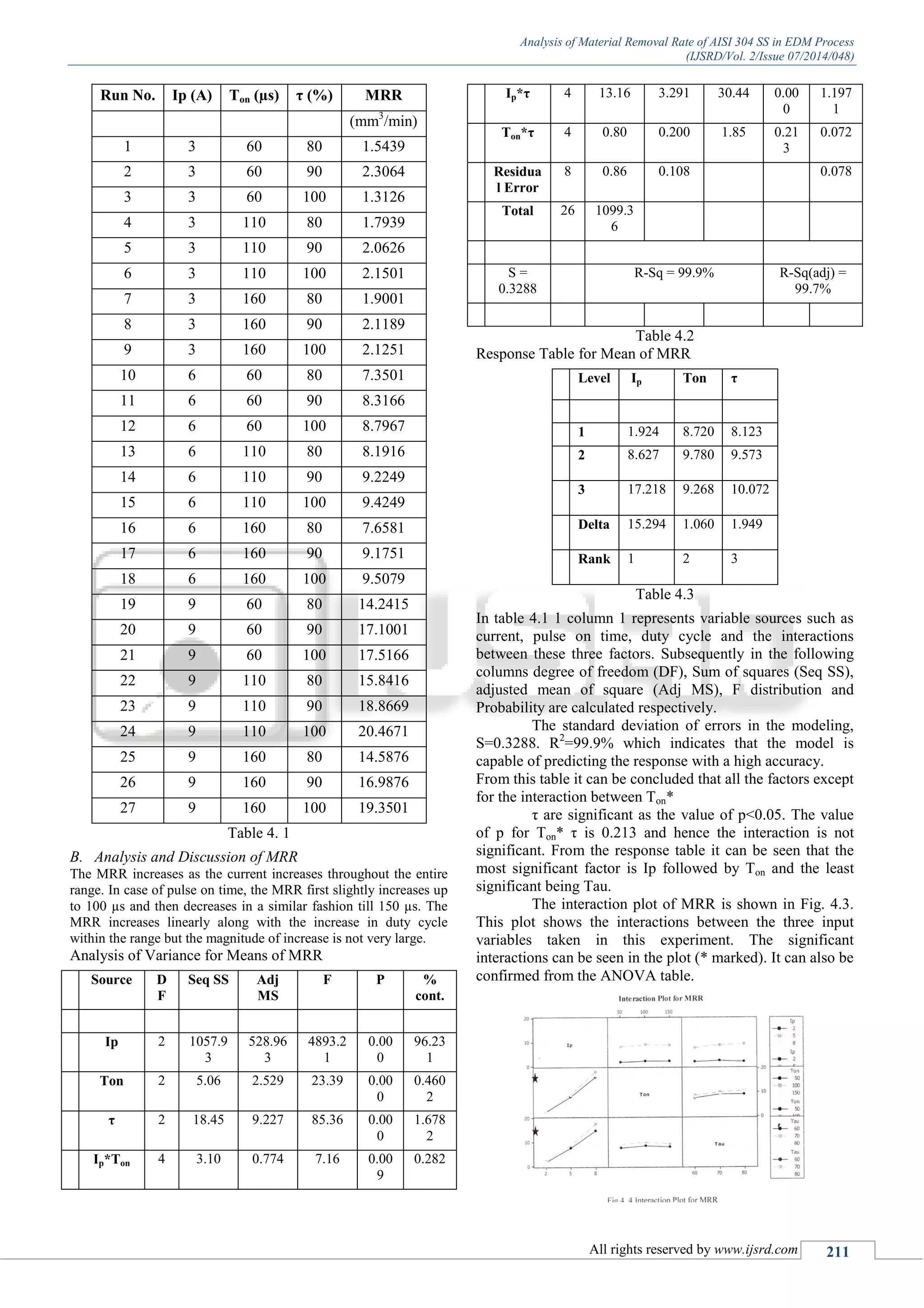
The study analyzes the material removal rate (MRR) of AISI 304 stainless steel using electric discharge machining (EDM) with various input parameters, such as current, pulse on time, and duty cycle. It was found that peak current significantly influences MRR, while pulse on time affects it non-linearly, peaking at 100 μs before decreasing. The research utilized a Taguchi method to create an L27 orthogonal array for experiments and concluded that current is the most critical factor affecting MRR, followed by pulse on time and duty cycle.