Download to read offline

![International Journal of Mechanical Engineering and Technology (IJMET), ISSN 0976 – 6340(Print),
ISSN 0976 – 6359(Online), Volume 5, Issue 6, June (2014), pp. 14-27 © IAEME
18
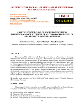
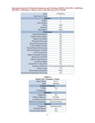
Bounding Box
Length X 3.0001e-002 m
Length Y 8.6052e-002 m
Length Z 3.7476e-002 m
Properties
Volume 6.9165e-005 m³
Mass 0.54295 kg
Centroid X 1.4936e-002 m
Centroid Y 2.6577e-002 m
Centroid Z 1.6318e-002 m
Moment of Inertia Ip1 3.1446e-004 kg·m²
Moment of Inertia Ip2 8.3141e-005 kg·m²
Moment of Inertia Ip3 3.1255e-004 kg·m²
Statistics
Nodes 4418
Elements 854
Mesh Metric None
Coordinate Systems
TABLE 4
Model (A4) > Coordinate Systems > Coordinate System
Object Name Global Coordinate System
State Fully Defined
Definition
Type Cartesian
Ansys System Number 0.
Origin
Origin X 0. m
Origin Y 0. m
Origin Z 0. m
Directional Vectors
X Axis Data [ 1. 0. 0. ]
Y Axis Data [ 0. 1. 0. ]
Z Axis Data [ 0. 0. 1. ]
Mesh
TABLE 5
Model (A4) > Mesh
Object Name Mesh
State Solved
Defaults
Physics Preference Mechanical
Relevance 0
Sizing](https://image.slidesharecdn.com/30120140506002-140627022742-phpapp02/85/30120140506002-5-320.jpg)
![International Journal of Mechanical Engineering and Technology (IJMET), ISSN 0976 – 6340(Print),
ISSN 0976 – 6359(Online), Volume 5, Issue 6, June (2014), pp. 14-27 © IAEME
26
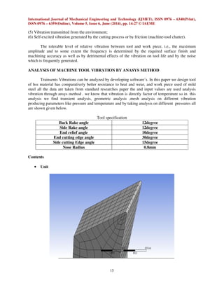
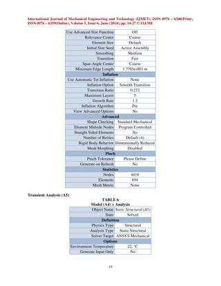
TABLE 23
High Speed Steel > Strain-Life Parameters
Strength
Coefficient Pa
Strength
Exponent
Ductility
Coefficient
Ductility
Exponent
Cyclic Strength
Coefficient Pa
Cyclic Strain
Hardening
Exponent
9.2e+008 -0.106 0.213 -0.47 1.e+009 0.2
TABLE 24
High Speed Steel > Relative Permeability
Relative Permeability
10000
TABLE 25
High Speed Steel > Isotropic Elasticity
Temperature C Young's Modulus Pa Poisson's Ratio
2.e+011 0.3
7. CONCLUSION
Thus we have seen the various aspects of machine tools vibrations and their effects. It has
been seen that the effect of vibrations can be disastrous. It may lead to undesirable results on the
work piece. Hence to minimize the vibrations in the tools a lot of research and study has been done.
This has drastically changed the machine efficiency and also minimized the harmful effects of
vibrations on the workers. With the advent of technology, software’s and highly precision
instruments have been developed to measure and analyze the vibrations caused in tools and to bring
up solutions quickly. It has become easier to evaluate the unwanted motions at different parts of a
machine and to rectify it. Hence it may be concluded that a machine tool should be designed keeping
all kinds of errors in mind.
8. REFERENCES
8.1 BOOKS
[1] Harris' Shock and Vibration Handbook 6th.Ed.(2009)
[2] James L. Taylor, The Vibration Analysis Handbook
[3] E.I. Rivin, Machine Tool Vibration
[4] MECHANICAL VIBRATION BY G.K. GROVER 8TH
EDITION
[5] Mechanical vibration by vp Singh.
8.2 JOURNALS AND TECHNICAL PAPERS
[6] Eiji Nabata, Yuji Terasaka Jig Rigidity Evaluation Technology by Vibration Analysis, VOL.
52, 2006.
[7] S. Braun Adaptronic Vibration Damping for Machine Tools.
[8] S.Y. Lin, Y.C. Fang, C.W. Huang, Improvement strategy for machine tool vibration induced
from the movement of a counterweight during machining process, February 2008.](https://image.slidesharecdn.com/30120140506002-140627022742-phpapp02/85/30120140506002-13-320.jpg)
![International Journal of Mechanical Engineering and Technology (IJMET), ISSN 0976 – 6340(Print),
ISSN 0976 – 6359(Online), Volume 5, Issue 6, June (2014), pp. 14-27 © IAEME
27
[9] Kourosh Tatar, Per Gren, Measurement of milling tool vibrations during cutting using laser
vibrometry.
[10] John G .Cherng, Mahmut Eksioglu, Kemal Kızılaslan, Vibration reduction of pneumatic
percussive rivet tools: Mechanical and ergonomic re-design approaches.
[11] Effect of cutting parameters on surface roughness and cutting forces in turning mild steel by
research journal of recents sciences vol.1(10), 19-26, October (2012) for standard design
parameters for tool design.
[12] Optimization of cutting parameters on mild steel with hss & cemented carbide tipped tools
using Ann by Proff A.V.N .L SHARMA(2006).
[13] Shaw metal cutting principle, Oxford University press (2006).
[14] Basic machining refrenance handbook, industrial press (2001).
[15] Analysis of cutting force during milling with regards to dependency on the penetration angle
(2009).
[16] Patel K. Batish and Bhattacharya A optimization of t surface roughness in an end milling
operation using nested experimental design (2009).
[17] Mile j.R-square, Adjusted R-squared, Encyclopedia of stastican Behavioral science, john
Wiley and son’s ltd (2005).
[18] Ricci L and Martinez R, Adjusted R2 –Type measure for tweedy model, computational
statics and data analysis.(2008)
[19] Sharma V.S,, Sharma S.K, and Sharma A.K, cutting wear estimation for turning, journal of
intelligent manufacturing (2007)
[20] Montgomery, D.C, Design and Analysis of experiment, John Wiley and sons (2001)
[21] Das M.N and Girl N.C, Design and analysis of experiment second New age international
p. ltd New Delhi(1999)
[22] Rodrigues L.I.R, Kantharaj B, and Murthy B.R.N Effect of cutting Parameters on surface
roughness and cutting forces in turning mild steel (2012).
[23] Prabhat Kumar Sinha, Rakesh Kumar Maurya, Rajneeshpandey and Vijay Kumar Yadav,
“Analysis of Residual Stresses and Distortions in Tig-Welded Stainless Steel Pipe”,
International Journal of Mechanical Engineering & Technology (IJMET), Volume 5, Issue 5,
2014, pp. 13 - 27, ISSN Print: 0976 – 6340, ISSN Online: 0976 – 6359.
[24] Prabhat Kumar Sinha, Rakesh Kumar Maurya, Rajneeshpandey and Vijay Kumar Yadav,
“Analysis for Free Vibration of Laminated Composite & Sandwich Plates with the Help of
Euler-Lagrange Equation Based on First Order Shear Deformation Theory, Formulations and
Solution to the Natural Frequency & Compare to Obtained Results”, International Journal of
Mechanical Engineering & Technology (IJMET), Volume 5, Issue 5, 2014, pp. 45 - 53,
ISSN Print: 0976 – 6340, ISSN Online: 0976 – 6359.
[25] Ganesan.H and Mohankumar.G, “Study on Optimization of Machining Parameters in
Turning Process using Evolutionary Algorithm with Experimental Verification”,
International Journal of Mechanical Engineering & Technology (IJMET), Volume 2, Issue 1,
2011, pp. 10 - 21, ISSN Print: 0976 – 6340, ISSN Online: 0976 – 6359.
[26] Pravin Kumar.S, Venkatakrishnan.R and Vignesh Babu.S, “Process Failure Mode and Effect
Analysis on End Milling Process- A Critical Study”, International Journal of Mechanical
Engineering & Technology (IJMET), Volume 4, Issue 5, 2013, pp. 191 - 199, ISSN Print:
0976 – 6340, ISSN Online: 0976 – 6359.
[27] R S Rajpurohit and R S Prasad, “Analysis of Mechanical Structure Under Vibration using
Vibration Measuring System”, International Journal of Mechanical Engineering &
Technology (IJMET), Volume 4, Issue 1, 2013, pp. 134 - 141, ISSN Print: 0976 – 6340,
ISSN Online: 0976 – 6359.](https://image.slidesharecdn.com/30120140506002-140627022742-phpapp02/85/30120140506002-14-320.jpg)

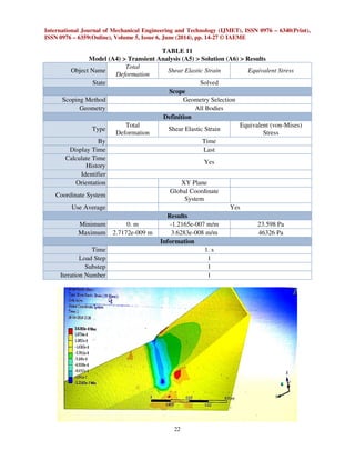
This document analyzes and models single point cutting of an HSS material tool using ANSYS to optimize transient vibration parameters like temperature and pressure. It describes the tool geometry and material properties and performs a transient analysis in ANSYS applying different pressure loads over time. The results show maximum deformations, strains, and stresses remain below yield criteria, with safety factors all above 10.


![[IJET-V1I6P14] Authors : M.S.Patil, J.G.Patil, R.R.Borase](https://cdn.slidesharecdn.com/ss_thumbnails/ijet-v1i6p14-160110010520-thumbnail.jpg?width=640&height=640&fit=bounds)