Download to read offline


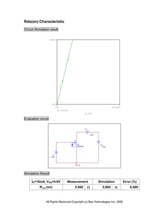

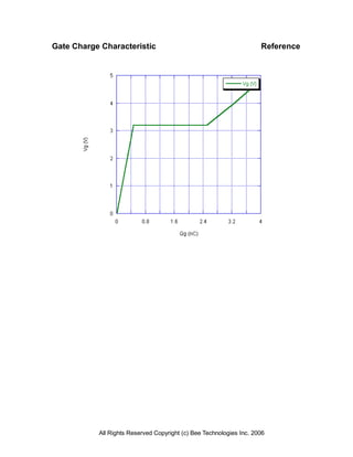


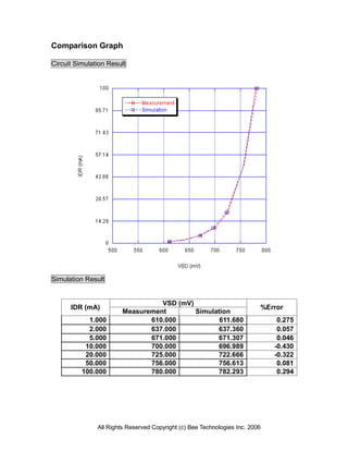


The document presents a comprehensive device modeling report for the 2SK3938 MOSFET, detailing various model parameters provided by the manufacturer, Panasonic. It includes circuit simulation results and characteristics such as transconductance, output, gate charge, and zener voltage across different configurations and operating conditions. The data is supported by measurement comparisons, highlighting measurement errors and confirming the accuracy of the simulations.


