Download to read offline


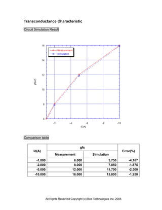


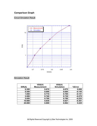
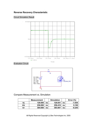


This document summarizes the modeling of a Power MOSFET transistor. It includes: 1) Details of the MOSFET part number and manufacturer. 2) Descriptions of the SPICE model parameters used to simulate the MOSFET. 3) Simulation results that compare measurements of the MOSFET's electrical characteristics to the model, such as transconductance, Vgs-Id curve, and switching times. 3) Circuit schematics used to perform the simulations and measure characteristics like output, forward current, and reverse recovery.


