The document provides information about a machine monitoring system, including:
1. The monitoring system consists of a monitor panel and switch panel that give warnings of abnormalities and show machine conditions.
2. The monitor panel displays information like engine RPM, temperatures, pressures, and warns of issues. It is controlled by a CPU and selects display modes.
3. Abnormal conditions cause warning lights and buzzers, and errors are recorded to troubleshoot issues. The monitoring system oversees the machine's functions and alerts operators to problems.
Ini adalah pertemuan tentang diagram blok, reduksi dan hasilnya dengan fungsi alih. Digunakan untuk pertemuan mata kuliah Teknik Kendali di prodi Sistem Komputer
Ini adalah pertemuan tentang diagram blok, reduksi dan hasilnya dengan fungsi alih. Digunakan untuk pertemuan mata kuliah Teknik Kendali di prodi Sistem Komputer
Tulisan ini mengulas teori pada proses Sampling and Hold. Proses ini merupakan salah satu metode untuk mencuplik atau mensampling sinyal informasi yang sedang diolah dalam proses pemodulasian. Output proses ini berupa sinyal PAM (Pulse Amplitude Modulation).
Cara kerja rangkaian up counter dan down counterPT.goLom na
http://technomoderen.blogspot.com/
http://technomoderen.blogspot.com
Note : bila sobat mau cari2 bahan gak ketemu , sobat bisa request kok sma sya ...
:D
mumpung hti ane lg baik neh , hehehe
info lebih lanjut
hub : Riszqi Pujangga (facebook)
081990334647 (sms) no call, krn ane kerja lembur ..... :)
dan sobat bsa juga kunjungi my web di atas,
thanks
ANALISIS PENCARIAN RUTE TERPENDEK PADA JARINGAN KOMPUTER DENGAN MENGGUNAKAN ...Simon Patabang
Salah satu cara mengatasi masalah kecepatan transfer data tersebut adalah dengan menggunakan algoritma genetika untuk melakukan proses pencarian rute terpendek yang akan dilewati oleh paket-paket data menuju titik tujuan. Algoritma genetika adalah metode yang akan digunakan untuk mencari rute terpendek sebagai lintasan optimal yang dilewati paket-paket data dari satu router ke router lain dalam jaringan komputer.
Monitoring dan Nutrisi Otomatis Tanaman Hidroponik dengan dengn Sensor Ultras...Ade Herdiana
Project Instrumentasi
Teknik Refrigerasi dan Tata Udara - Politeknik Negeri Bandung
2A - grup 3
- Ade Herdiana (151611001)
- Rizkya Nadila (151611026)
- Yossa Fariz R (151611031)
more info : ade.herdiana99@gmail.com
Definisi: Mikroprosesor adalah suatu chip (IC=integrated circuits) yang di dalamnya terkandung rangkaian ALU (arithmetic-logic unit), rangkaian CU (control unit), dan register-register. Mkroprosesor disebut juga dengan CPU (Central Processing Unit)
ALU: menyediakan fungsi pengolahan
CU: mengontrol fungsi prosesor
Register: penyimpan sementara dalam mikroprosesor
Mikro,
Catalog Thiết Bị Điện Mikro, Catalog Thiết Bị Điện,
Catalog Phụ Kiện Mikro, Catalog Phụ Kiện,
Catalog Mikro, Catalog,
http://dienhathe.com,
Chi tiết các sản phẩm khác của Mikro tại https://dienhathe.com
Xem thêm các Catalog khác của Mikro tại https://dienhathe.info
Để nhận báo giá sản phẩm Mikro vui lòng gọi: 0907.764.966
Refer to the User's Fadal Power On/Off Operator Manual. Do not install substitute parts or modify the CNC machine without consulting a safety engineer.
https://itscnc.com/fadal-manuals
When you’re looking to purchase replacement parts for your CNC, no one has more industry knowledge or better pricing than Independent Technology Service Inc.
At ITSCNC quality is key and that’s true with our replacement items for CNC machines.
ITSCNC is your one-stop shop for all fadal CNC parts. We offer you the best quality CNC parts with various features.
Refer to the User's Fadal Power On/Off Operator Manual. Do not install substitute parts or modify the CNC machine without consulting a safety engineer.
Download or check out all our Fadal CNC machines and parts manuals. We provide very simple and concise, step-by-step instructions on how to install and get your replacement Fadal parts in and running. With our documentation, we also include Preventative Maintenance tips to help avoid future failures. Simply email us at parts@itscnc.com or go through our website.
https://itscnc.com/parts-manuals
Looking for guidance on operating your Fadal CNC machine? Look no further than the Fadal Operator's Manual available through ITSCNC. This comprehensive manual provides you with the essential information needed to efficiently and effectively utilize your Fadal CNC machine. From setup to maintenance and troubleshooting, this manual covers it all, ensuring that you can make the most of your equipment. Don't leave your CNC operation to chance – get your Fadal Operator's Manual from ITSCNC today and harness the full potential of your Fadal CNC machine.
Industrial Training at Shahjalal Fertilizer Company Limited (SFCL)MdTanvirMahtab2
This presentation is about the working procedure of Shahjalal Fertilizer Company Limited (SFCL). A Govt. owned Company of Bangladesh Chemical Industries Corporation under Ministry of Industries.
TECHNICAL TRAINING MANUAL GENERAL FAMILIARIZATION COURSEDuvanRamosGarzon1
AIRCRAFT GENERAL
The Single Aisle is the most advanced family aircraft in service today, with fly-by-wire flight controls.
The A318, A319, A320 and A321 are twin-engine subsonic medium range aircraft.
The family offers a choice of engines
CFD Simulation of By-pass Flow in a HRSG module by R&R Consult.pptxR&R Consult
CFD analysis is incredibly effective at solving mysteries and improving the performance of complex systems!
Here's a great example: At a large natural gas-fired power plant, where they use waste heat to generate steam and energy, they were puzzled that their boiler wasn't producing as much steam as expected.
R&R and Tetra Engineering Group Inc. were asked to solve the issue with reduced steam production.
An inspection had shown that a significant amount of hot flue gas was bypassing the boiler tubes, where the heat was supposed to be transferred.
R&R Consult conducted a CFD analysis, which revealed that 6.3% of the flue gas was bypassing the boiler tubes without transferring heat. The analysis also showed that the flue gas was instead being directed along the sides of the boiler and between the modules that were supposed to capture the heat. This was the cause of the reduced performance.
Based on our results, Tetra Engineering installed covering plates to reduce the bypass flow. This improved the boiler's performance and increased electricity production.
It is always satisfying when we can help solve complex challenges like this. Do your systems also need a check-up or optimization? Give us a call!
Work done in cooperation with James Malloy and David Moelling from Tetra Engineering.
More examples of our work https://www.r-r-consult.dk/en/cases-en/
Student information management system project report ii.pdfKamal Acharya
Our project explains about the student management. This project mainly explains the various actions related to student details. This project shows some ease in adding, editing and deleting the student details. It also provides a less time consuming process for viewing, adding, editing and deleting the marks of the students.
Vaccine management system project report documentation..pdfKamal Acharya
The Division of Vaccine and Immunization is facing increasing difficulty monitoring vaccines and other commodities distribution once they have been distributed from the national stores. With the introduction of new vaccines, more challenges have been anticipated with this additions posing serious threat to the already over strained vaccine supply chain system in Kenya.
Courier management system project report.pdfKamal Acharya
It is now-a-days very important for the people to send or receive articles like imported furniture, electronic items, gifts, business goods and the like. People depend vastly on different transport systems which mostly use the manual way of receiving and delivering the articles. There is no way to track the articles till they are received and there is no way to let the customer know what happened in transit, once he booked some articles. In such a situation, we need a system which completely computerizes the cargo activities including time to time tracking of the articles sent. This need is fulfilled by Courier Management System software which is online software for the cargo management people that enables them to receive the goods from a source and send them to a required destination and track their status from time to time.
Hybrid optimization of pumped hydro system and solar- Engr. Abdul-Azeez.pdffxintegritypublishin
Advancements in technology unveil a myriad of electrical and electronic breakthroughs geared towards efficiently harnessing limited resources to meet human energy demands. The optimization of hybrid solar PV panels and pumped hydro energy supply systems plays a pivotal role in utilizing natural resources effectively. This initiative not only benefits humanity but also fosters environmental sustainability. The study investigated the design optimization of these hybrid systems, focusing on understanding solar radiation patterns, identifying geographical influences on solar radiation, formulating a mathematical model for system optimization, and determining the optimal configuration of PV panels and pumped hydro storage. Through a comparative analysis approach and eight weeks of data collection, the study addressed key research questions related to solar radiation patterns and optimal system design. The findings highlighted regions with heightened solar radiation levels, showcasing substantial potential for power generation and emphasizing the system's efficiency. Optimizing system design significantly boosted power generation, promoted renewable energy utilization, and enhanced energy storage capacity. The study underscored the benefits of optimizing hybrid solar PV panels and pumped hydro energy supply systems for sustainable energy usage. Optimizing the design of solar PV panels and pumped hydro energy supply systems as examined across diverse climatic conditions in a developing country, not only enhances power generation but also improves the integration of renewable energy sources and boosts energy storage capacities, particularly beneficial for less economically prosperous regions. Additionally, the study provides valuable insights for advancing energy research in economically viable areas. Recommendations included conducting site-specific assessments, utilizing advanced modeling tools, implementing regular maintenance protocols, and enhancing communication among system components.
Explore the innovative world of trenchless pipe repair with our comprehensive guide, "The Benefits and Techniques of Trenchless Pipe Repair." This document delves into the modern methods of repairing underground pipes without the need for extensive excavation, highlighting the numerous advantages and the latest techniques used in the industry.
Learn about the cost savings, reduced environmental impact, and minimal disruption associated with trenchless technology. Discover detailed explanations of popular techniques such as pipe bursting, cured-in-place pipe (CIPP) lining, and directional drilling. Understand how these methods can be applied to various types of infrastructure, from residential plumbing to large-scale municipal systems.
Ideal for homeowners, contractors, engineers, and anyone interested in modern plumbing solutions, this guide provides valuable insights into why trenchless pipe repair is becoming the preferred choice for pipe rehabilitation. Stay informed about the latest advancements and best practices in the field.
Automobile Management System Project Report.pdfKamal Acharya
The proposed project is developed to manage the automobile in the automobile dealer company. The main module in this project is login, automobile management, customer management, sales, complaints and reports. The first module is the login. The automobile showroom owner should login to the project for usage. The username and password are verified and if it is correct, next form opens. If the username and password are not correct, it shows the error message.
When a customer search for a automobile, if the automobile is available, they will be taken to a page that shows the details of the automobile including automobile name, automobile ID, quantity, price etc. “Automobile Management System” is useful for maintaining automobiles, customers effectively and hence helps for establishing good relation between customer and automobile organization. It contains various customized modules for effectively maintaining automobiles and stock information accurately and safely.
When the automobile is sold to the customer, stock will be reduced automatically. When a new purchase is made, stock will be increased automatically. While selecting automobiles for sale, the proposed software will automatically check for total number of available stock of that particular item, if the total stock of that particular item is less than 5, software will notify the user to purchase the particular item.
Also when the user tries to sale items which are not in stock, the system will prompt the user that the stock is not enough. Customers of this system can search for a automobile; can purchase a automobile easily by selecting fast. On the other hand the stock of automobiles can be maintained perfectly by the automobile shop manager overcoming the drawbacks of existing system.
About
Indigenized remote control interface card suitable for MAFI system CCR equipment. Compatible for IDM8000 CCR. Backplane mounted serial and TCP/Ethernet communication module for CCR remote access. IDM 8000 CCR remote control on serial and TCP protocol.
• Remote control: Parallel or serial interface.
• Compatible with MAFI CCR system.
• Compatible with IDM8000 CCR.
• Compatible with Backplane mount serial communication.
• Compatible with commercial and Defence aviation CCR system.
• Remote control system for accessing CCR and allied system over serial or TCP.
• Indigenized local Support/presence in India.
• Easy in configuration using DIP switches.
Technical Specifications
Indigenized remote control interface card suitable for MAFI system CCR equipment. Compatible for IDM8000 CCR. Backplane mounted serial and TCP/Ethernet communication module for CCR remote access. IDM 8000 CCR remote control on serial and TCP protocol.
Key Features
Indigenized remote control interface card suitable for MAFI system CCR equipment. Compatible for IDM8000 CCR. Backplane mounted serial and TCP/Ethernet communication module for CCR remote access. IDM 8000 CCR remote control on serial and TCP protocol.
• Remote control: Parallel or serial interface
• Compatible with MAFI CCR system
• Copatiable with IDM8000 CCR
• Compatible with Backplane mount serial communication.
• Compatible with commercial and Defence aviation CCR system.
• Remote control system for accessing CCR and allied system over serial or TCP.
• Indigenized local Support/presence in India.
Application
• Remote control: Parallel or serial interface.
• Compatible with MAFI CCR system.
• Compatible with IDM8000 CCR.
• Compatible with Backplane mount serial communication.
• Compatible with commercial and Defence aviation CCR system.
• Remote control system for accessing CCR and allied system over serial or TCP.
• Indigenized local Support/presence in India.
• Easy in configuration using DIP switches.
1. 5- 26
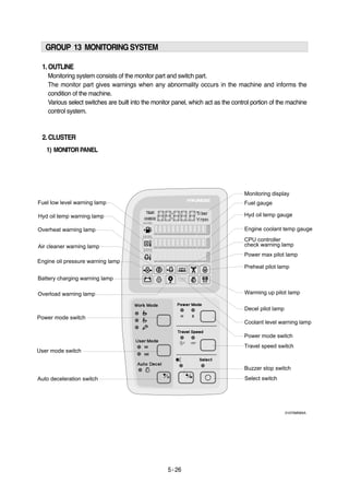
GROUP 13 MONITORING SYSTEM
1. OUTLINE
Monitoring system consists of the monitor part and switch part.
The monitor part gives warnings when any abnormality occurs in the machine and informs the
condition of the machine.
Various select switches are built into the monitor panel, which act as the control portion of the machine
control system.
2. CLUSTER
MONITORPANEL1)
21075MS65A
2. 5-27
CLUSTERCHECKPROCEDURE
Start key : ON
Check monitor initial 5 seconds
All lamps light up.
Buzzer sound.
Check monitor after 5 seconds : Indicate cluster version and machine condition
Cluster program version : CL : 1.4 Indicates program version 1.4 for 2 seconds.
Tachometer : 0rpm
Fuel gauge : All light up below appropriate level
Hydraulic temperature : All light up below appropriate level
Engine coolant temperature gauge : All light up below appropriate level
Warning lamp
During start key ON the engine oil pressure lamp and battery charging lamp go on, but it is not
abnormal.
When engine coolant temperature below 30°C, the warming up lamp lights up.
Indicating lamp state
Work mode selection : General work
Power mode selection : S mode
User mode selection : No LED ON
Auto decel LED : ON
Travel speed pilot lamp : Low(Turttle)
Start of engine
Check machine condition
Tachometer indicates at present rpm
Gauge and warning lamp : Indicate at present condition.
When normal condition : All warning lamp OFF
Work mode selection : General work
Power mode selection : S mode
User mode selection : No LED ON
Auto decel LED : ON
Travel speed pilot lamp : Low(Turttle)
When warming up operation
Warming up lamp : ON
10 seconds after engine started, engine speed increases to1200rpm(Auto decel LED : ON)
Others same as above ①.
When abnormal condition
The lamp lights up and the buzzer sounds.
If BUZZER STOP switch is pressed, buzzer sound is canceled but the lamp light up until normal
condition.
2)
(1)
①
②
a.
b.
a.
b.
c.
d.
e.
f.
※
※
(2)
③
①
②
③
a.
b.
※
c.
d.
e.
f.
g.
a.
b.
※
a.
b.
a.
b.
c.
d.
e.
4. 5-29
This displays the current time and machine information such as
engine rpm, coolant/hydraulic oil temperature, hydraulic oil
pressure and also error codes.
Refer to the page 5-34 for details.
(1)
※
This gauge indicates the amount of fuel in the fuel tank.
Fill the fuel when the white range or warning lamp blinks.
If the gauge illuminates the white range or warning lamp
blinks even though the machine is on the normal condition,
check the electric device as that can be caused by the
poor connection of electricity or sensor.
White range
FUEL GAUGE
This indicates the temperature of coolant.
・White range : Below 30°C(86°F)
・Green range : 30-105 °C(86-221°F)
・Red range : Above 105°C(221°F)
The green range illuminates when operating.
Keep idling engine at low speed until the green range
illuminates before operation of machine.
When the red range illuminates, reduce the load on the system.
If the gauge stays in the red range, stop the machine and
check the cause of the problem.
Red range
HYDRAULIC OIL TEMPERATURE GAUGE
Red range
ENGINE COOLANT TEMPERATURE GAUGE
(1)
(2)
※
(1)
(2)
(3)
(4)
This indicates the temperature of coolant.
・White range : Below 30°C(86°F)
・Green range : 30-105 °C(86-221°F)
・Red range : Above 105°C(221°F)
The green range illuminates when operating.
Keep idling engine at low speed until the green range
illuminates before operation of machine.
When the red range illuminates, turn OFF the engine, check
the radiator and engine.
(1)
(2)
(3)
(4)
21073CD04
21073CD05
21073CD05
2)
3)
4)
4.CLUSTERFUNCTION
MONITORINGDISPLAY1)
14073CD03
5. 5- 30
This lamp blinks and the buzzer sounds when the level of fuel
is below 31ℓ(8.2U.S. gal).
Fill the fuel immediately when the lamp blinks.
FUEL LOW LEVEL WARNING LAMP
(1)
(2)
5)
This lamp blinks and the buzzer sounds when the temperature
of coolant is over the normal temperature 110°C( 230°F) .
Check the cooling system when the lamp blinks.
HYDRAULIC OIL TEMPERATURE WARNING LAMP
(1)
(2)
6)
This warning lamp operates and the buzzer sounds when the
temperature of hydraulic oil is over 105°C(221°F).
Check the hydraulic oil level when the lamp blinks.
Check for debris between oil cooler and radiator.
OVERHEAT WARNING LAMP
(1)
(2)
(3)
7)
This lamp blinks and the buzzer sounds after starting the
engine because of pressure.
If the lamp blinks during engine operation, shut OFF engine
immediately. Check oil level.
ENGINE OIL PRESSURE WARNING LAMP
(1)
(2)
8)
This lamp is operated by the vacuum caused inside when the
filter of air cleaner is clogged which supply air to the engine.
Check the filter and clean or replace it when the lamp blinks.
AIR CLEANER WARNING LAMP
(1)
(2)
9)
21073CD04A
21073CD05A
21073CD06A
21073CD07
21073CD08
6. 5-31
This lamp blinks and the buzzer sounds when the coolant is
below LOW in the reservoir tank of radiator.
Check the reservoir tank when the lamp blinks.
COOLANT LEVEL WARNING LAMP
(1)
(2)
10)
Communication problem with CPU controller makes the lamp
blinks and the buzzer sounds.
Check if any fuse for CPU burnt off.
If not check the communication line between them.
(1)
(2)
(3)
CPU CONTROLLER CHECK WARMING LAMP11)
This lamp blinks and the buzzer sounds when the starting
switch is ON, it is turned OFF after starting the engine.
Check the battery charging circuit when this lamp blinks during
engine operation.
BATTERY CHARGING WARNING LAMP
(1)
(2)
12)
When the machine is overload, the overload warning lamp
blinks during the overload switch ON.
(1)
OVERLOAD WARNING LAMP13)
The lamp will be ON when pushing power max switch on the
LH RCV lever.
(1)
POWER MAX PILOT LAMP14)
21073CD09
21073CD10
21073CD13
21073CD15
21073CD11
7. 5- 32
Operating auto decel or one touch decel makes the lamp ON.
The lamp will be ON when pushing one touch decel switch on
the LH RCV lever.
(1)
(2)
DECEL PILOT LAMP15)
This lamp is turned ON when the coolant temperature is below
30°C(86 °F).
The automatic warming up is cancelled when the engine
coolant temperature is above 30 °C, or when 10 minutes have
passed since starting.
WARMING UP PILOT LAMP
(1)
(2)
16)
Turning the start key switch ON position starts preheating in
cold weather.
Start the engine as this lamp is OFF.
PREHEAT PILOT LAMP
(1)
(2)
17)
This switch is to select the machine operation mode, which
shifts from general operation mode to heavy operation mode
and breaker mode in a raw by pressing the switch.
・ : Heavy duty work mode
・ : General work mode
・ : Breaker operation mode
Refer to the page 5-4 for details.
WORK MODE SWITCH
(1)
※
18)
USER MODE SWITCH19)
This switch is to select the memory sets, at which you can
change the engine and pump power and memorize it into MI
and MII mode for your preference.
Refer to the page 5-5 for details.
(1)
※
21073CD17
21073CD18
21073CD12
21073CD20
21073CD21
8. 5-33
AUTO DECELERATION SWITCH20)
The lamp of selected mode is turned ON by pressing the
switch( ).
・H : High power work.
・S : Standard power work.
POWER MODE SWITCH
(1)
21)
This switch is to control the travel speed which is changed to
high speed(Rabbit mark) by pressing the switch and low
speed(Turtle mark) by pressing it again.
TRAVEL SPEED CONTROL SWITCH
(1)
22)
When the starting switch is turned ON first, normally the alarm
buzzer sounds for 2 seconds during lamp check operation.
The red lamp lights ON and the buzzer sounds when the
machine has a problem.
In this case, press this switch and buzzer stops, but the red
lamp lights until the problem is cleared.
BUZZER STOP SWITCH
(1)
(2)
23)
This switch is used to actuate or cancel the auto deceleration
function.
When the switch actuated and all control levers and pedals are
at neutral position. Engine speed will be lowered automatically
to save fuel consumption.
・Light ON : Auto deceleration function is selected.
・Light OFF : Auto deceleration function is cancelled so that the
engine speed increased to previous setting value.
Operating the auto deceleration function makes the decel
indicating lamp on the LCD panel ON.
(1)
(2)
21073CD22
21073CD23
21073CD24
21073CD25
9. 5- 34
This switch is used to select the monitor display function.
Refer to the page 5-35 for details.
If the switch is pressed for 3 seconds in time display mode, it is
selected time adjusting function, as below.
・Hour by auto decel( )switch
・Minute by buzzer stop( ) switch.
After time set, the switch is pressed, it returns to clock display.
SELECT SWITCH
(1)
※※
(2)
(3)
24)
21073CD25A
10. 5- 35
5. MONITORING DISPLAY
OUTLINE
Information of machine performance as monitored by the CPU controller can be displayed on the
cluster when the operator selects a display mode by touching SELECT switch alone or with BUZZER
STOP switch on the cluster as below.
1)
Way 1
Key switch
ON or START
Way 2
Touch AUTO DECEL
switch while pressing
BUZZER STOP at
group 1~4.
Group 0
(Default)
Group 1
(Volt, temp,
EPPR press,
version)
Group 2
(Error code)
Touch SELECT switch
once while pressing
BUZZER STOP.
In this group SELECT
LED ON
Touch SELECT switch
twice while pressing
BUZZER STOP.
In this group BUZZER
STOP LED blinks
How to select display mode
Group selection Display mode selection
NameDisplay group Display on the cluster
Group 3
(Switch input)
Touch SELECT switch
3 times while pressing
BUZZER STOP.
In this group SELECT
LED blinks at 0.5sec
interval
or
or
or
or
or
or
or
Initial
Touch SELECT 1 time
Touch SECLET 2 times
Touch SELECT 3 times
Option
(Only when
a pressure
sensor is
installed)
Default
Touch SELECT 1 time
Touch SELECT 2 times
Touch SELECT 3 times
Touch SELECT 4 times
Default
Touch SELECT 1 time
Press down( ) &
SELECT at the same time
Default
Touch SELECT 1 time
Touch SELECT 2 times
Touch SELECT 3 times
Touch SELECT 4 times
Touch SELECT 5 times
Touch SELECT 6 times
TouchSELECT
4times
TouchSELECT
5times
TouchSELECT
6times
Engine rpm
Time
Power shift pressure
(EPPR valve)
CPU model & version
Front pump pressure
Rear pump pressure
Pilot pressure
Battery voltage(V)
Potentiometer voltage(V)
Accel dial voltage(V)
Hydraulic oil
temperature(°C)
Coolant temperature(°C)
Current error
Recorded error
(Only key switch ON)
Recorded error deletion
(Only key switch ON)
Pump prolix switch
Auto decel pressure switch
Power boost switch
Travel oil pressure switch
One touch decel switch
Travel alarm switch
Preheat switch
11. 5-36
or
or
or
or
or
or
or
or
Group 4
(Output)
Touch SELECT switch
4 times while pressing
BUZZER STOP.
In this group SELECT
LED blinks at 1sec
interval
How to select display mode
Group selection Display mode selection
NameDisplay group Display on the cluster
Hourmeter
Neutral relay
(Anti-restart relay)
Travel speed solenoid
Power boost solenoid
(2-stage relief solenoid)
Boom priority solenoid
Travel alarm
Max flow cut off solenoid
Preheat relay
Default
Touch SELECT 1 time
Touch SELECT 2 times
Touch SELECT 3 times
Touch SELECT 4 times
Touch SELECT 5 times
Touch SELECT 6 times
Touch SELECT 7 times
※By touching SELECT switch once while pressing BUZZER STOP, display group shifts.
Example : Group 0 1 2 3 4 0
12. 5- 37
DESCRIPTIONOFMONITORINGDISPLAY2)
Group Display Name Description
2250 rpm
TIME 12 : 30
EP : 10bar
21 : C1.4
*21 : C5.0
P1 : 100bar
(Option)
P2 : 200bar
(Option)
P3 : 30bar
(Option)
b : 24.8V
Po : 2.5V
dL : 3.8V
Hd : 50°°C
Ct : 85°°C
It displays current engine speed detected by engine speed
sensor from 500 to 3000rpm.
Range : 500~3000rpm by 10rpm
It displays current time(12 is hour and 30 is minute)
Range : Hour(1~12), minute(00~59)
It shows that pump power shift pressure of EPPR valve being
controlled by the CPU controller is 10bar.
Range : 00~50bar by 1bar
It shows that machine model(R210LC-7) and the program
version of the CPU controller is 1.4.
Version display range : 0.0~9.9 by 0.1
It displays front pump pressure of 100bar which is detected by
pressure sensor.
Range : 000~500bar by 10bar
It displays rear pump pressure of 200bar which is detected by
pressure sensor.
Range : 000~500bar by 10bar
It displays pilot pump pressure of 30bar which is detected by
pressure sensor.
Range : 00~50bar by 1bar
It shows that battery power of 24.8V is supplied into CPU controller.
Range : 00.0~48.0V by 0.1V
It shows that potentiometer signal voltage is 2.5V.
Range : 0.0~5.0V by 0.1V
It shows that accel dial signal voltage is 3.8V.
Range : 0.0~5.0V by 0.1V
It shows that hydraulic oil temperature detected by temperature
sensor is 50°C.
Range : 0~150°C by 1°C
It shows that coolant oil temperature detected by temperature
sensor is 50°C.
Range : 0~150°C by 1°C
Engine speed
Time
Power shift
pressure of
EPPR valve
Model and CPU
program version
Front pump
pressure
Rear pump
pressure
Pilot pump
pressure
Battery voltage
Potentiometer
voltage
Accel dial
voltage
Hydraulic oil
temperature
Coolant
temperature
Group 1
Group 0
* : TIER II Only
13. 5-38
Group Display Name Description
CHECK Er : 03
TIME Er : 03
TIME Er : 00
PP : on or oFF
dP : on or oFF
Pb : on or oFF
oP : on or oFF
od : on or oFF
br : on or oFF
PH : on or oFF
It shows that current error of 03(Short circuit in pump EPPR valve
system)isdiagnosedbyselfdiagnosissystemintheCPUcontroller.
If more than 2 errors, when pressing or switch, other
error codes show.
Range : 00~58
It shows recorded error code of 03 which is diagnosed before.
If more than 2 error codes, when pressing or switch,
other error codes show.
Range : 00~58
It shows all recorded error codes are removed in the CPU
controller memory.
Current error
Recorded error
Recorded error
deletion
Pump prolix
switch
Auto decel
pressure switch
Power
boost switch
Travel oil
pressure switch
One touch
decel switch
Travel alarm
switch
Preheat switch
Group 3
Group 2
Shows that pump prolix switch is turned on(At
emergency position).
Shows that pump prolix switch is turned off(At normal
position).
Shows that auto decel pressure switch is pressed on
(No operation of control lever).
Shows that auto decel pressure switch is released off
(Operation of control lever).
Shows that power boost switch is pressed on
(Activated).
Shows that power boost switch is released off
(Canceled).
Shows that travel oil pressure switch is pressed on
(No operation of travel control lever).
Shows that travel oil pressure switch is released off
(Operation of travel control lever).
Shows that one touch decel switch is pressed.
Shows that one touch decel switch is released.
Shows that travel alarm function is selected.
Shows that travel alarm function is canceled.
Shows that preheat switch is pressed.
Shows that preheat switch is released.
PP : on
PP : oFF
dP : on
dP : oFF
Pb : on
Pb : oFF
oP : on
oP : oFF
od : on
od : oFF
br : on
br : oFF
PH : on
PH : oFF
14. 5- 39
Group Display Name Description
Ho : on or oFF
nr : on or oFF
ts : on or oFF
PS : on or oFF
bs : on or oFF
Ru : on or oFF
FS : on or oFF
PR : on or oFF
Shows that hourmeter is activated by CPU controller.
Shows that hourmeter is turned off.
Shows that neutral relay for anti-restarting function is
activated(Engine start is possible).
Shows that neutral relay is turned off to disable the
engine restart.
Shows that travel speed solenoid is activated
(High speed).
Shows that travel speed solenoid is released
(Low speed).
Shows that power boost solenoid is activated to
maximize the power(Power up).
Shows that power boost solenoid is turned off(Cancel
the power boost function).
Shows that boom priority solenoid is activated.
Shows that boom priority solenoid is released.
Shows that travel buzzer is activated.
Shows that travel buzzer is canceled.
Shows that max flow cut off solenoid is activated.
Shows that max flow cut off solenoid is released.
Shows that preheat relay is activated.
Shows that preheat relay is released.
Hourmeter
Neutral relay
(Anti-restart
relay)
Travel speed
solenoid
Power boost
solenoid
Boom priority
solenoid
Travel alarm
Max flow cut off
solenoid
Preheat relay
Group 4
Ho : on
Ho : oFF
nr : on
nr : oFF
ts : on
ts : oFF
PS : on
PS : oFF
bs : on
bs : oFF
Ru : on
Ru :oFF
FS : on
FS : oFF
PR : on
PR : oFF