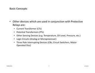
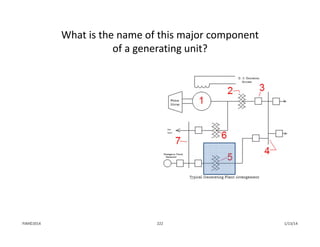
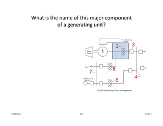
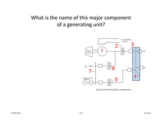
PJM State & Member Training Dept.
Power System Fundamentals
Relay Applications
Objectives
At the end of this presentation the Student will be able to:
• Describe the purpose of protective relays
• Identify relay protection scheme characteristics and components 
• Describe the impact of the loss of components on 
system protection
• Identify the types of transmission line protection and 
their characteristics
• Identify the types of transformer protection and their characteristics
• Identify the types of bus protection and their characteristics
• Identify the types of generator protection and their characteristics
1/13/142PJM©2014
Basic Concepts
in
Protection
1/13/14PJM©2014
Purpose of Protective Relaying
• To detect and isolate faulted or malfunctioning 
equipment in order to: 
1) limit the extent of the system disturbance and
2) maintain system reliability
1/13/144PJM©2014
200 A
Utility Distribution System
15 A 15 A 15 A
72” Plasma TV
Individual Device Fuse
Individually‐protected  
Branch CircuitsProtected 
Receptacles
Main Service Entrance Panel
The Source
1/13/14PJM©2014 5
Basic Concepts
• Relays are the intelligence in a Protective Scheme
• They monitor system “inputs” and operate when the monitored 
quantity exceeds a predefined limit
• Relay response will initiate a desirable system event that will aid in 
maintaining system reliability (i.e. trip a circuit breaker, throttle back a 
unit, etc)
1/13/146PJM©2014
Basic Concepts
• Other devices which are used in conjunction with Protective 
Relays are:
• Current Transformer (CTs)
• Potential Transformers (PTs)
• Other Sensing Devices (e.g. Temperature, Oil Level, Pressure, etc.)
• Logic Circuits (Analog or Microprocessor)
• Three Pole Interrupting Devices (CBs, Circuit Switchers, Motor 
Operated Disc)
1/13/147PJM©2014
Basic Concepts
• Most Relay schemes work to control a DC system
• DC System usually has rack of Batteries and a battery  charger
• Generally controls the tripping of CBs
• This why NERC compliance includes DC Control Circuitry and Batteries 
as part of the Relay Standards
1/13/148PJM©2014
Relay Scheme
Components
1/13/14PJM©2014
• The power source used for controlling power system equipment must be 
highly reliable and not subject to interruption by power system transients 
or outages
• Protection and control circuits are individually fused to guard against 
disrupting the entire DC system for problems on a particular branch circuit
• Amber lights often monitor the DC supply to individual branch circuits, 
giving a visual indication that the circuit is energized
AC
DC Control Systems
1/13/1410PJM©2014
Full DC
Voltage
½ DC
Voltage
½ DC
Voltage
Illustration Of 
Battery Ground Detection Lamps
For the normal, ungrounded condition 
shown, the two lamps each have equal 
voltage dropped across them and glow 
with equal brilliance
Intentional ground
reference connection
DC Control Systems
• With few special exceptions, DC systems operate ungrounded
• Power plants and most substations have some battery ground 
detection, very often including ground indicating lamps that visually 
alert personnel to inadvertent DC system grounds
1/13/14PJM©2014 11
• This same principal of DC ground detection is used in more sophisticated 
devices that provide an alarm contact instead of just a visual indication
• A single inadvertent ground on an ungrounded DC system is not 
catastrophic…the danger is that a second inadvertent ground could occur 
on the opposite side of the DC supply and short out the battery! 
Battery Ground Lamps Indicate A Solid Ground 
On The Positive Side Of The DC System
Illustration Of Actual Battery Ground Indicating Lamps
Normal Battery Ground Lamps
Approximately Equal Brilliance
DC Control Systems
1/13/1412PJM©2014
DC Control Systems
• COMMON CAUSES OF BATTERY GROUNDS
1/13/1413PJM©2014
Overview of Power 
System Protection
1/13/14PJM©2014
Overview of Power System Protection
• Key element to remember
• Protective Schemes are designed to have:
OVERLAPPING ZONES 
OF PROTECTION!
1/13/1415PJM©2014
Overlapping Zones of Protection
1/13/1416PJM©2014
Overview of Power System Protection
• Critical elements of the power system are protected by 
“Primary” and “Backup” relay systems
• Primary Schemes are generally high speed schemes 
(operate speed = 1 cycle)
• Backup Schemes can also be high speed but don’t have to be.  
System conditions dictate if this scheme has to be as fast as the 
primary scheme
1/13/1417PJM©2014
Instrument Transformers
• Instrument Transformers change primary voltages and 
currents into secondary quantities having proportional 
magnitudes and identical phase angle relationships
• Primary current is transformed by CTs (Current Transformers) and LCs 
(Linear Couplers)
• Primary voltage is transformed by PTs (Potential Transformers) and 
CCVTs (Coupling Capacitor Voltage Transformers)
1/13/14PJM©2014 18
Current Transformers (CTs)
• CTs transform high magnitude primary amps to secondary 
amp quantities within the current ratings of relays and meters
• CT ratios are typically expressed as Primary Amps/5 
• For example, a generator CT ratio expressed as 25000/5 means that 
5000 amps flowing in the primary circuit results in 1 amp flowing in 
the secondary circuits
• CTs that fit around breaker, generator, or transformer bushings are 
called bushing CTs; these are the most common type of CTs 
1/13/1419PJM©2014
If the secondary circuit of a load‐carrying CT is 
open‐circuited, the CT can produce high enough 
voltage to injure or kill personnel
Current Transformers (CTs)
• A CT is a nearly ideal current source…within the limits of its 
construction, a CT produces as much voltage as necessary to push 
secondary current proportional to the primary current through a 
connected load, no matter how large the load impedance
• Ohm’s Law, V = Z x I, describes how much voltage, V, a CT must produce to 
drive its current, I, through connected load impedance, Z…as Z gets bigger, 
V must also increase to satisfy the equation!
1/13/1420PJM©2014
Illustrations Of Externally Applied Current Transformers
ABOVE LEFT
Slipover CTs installed on a 69kV circuit breaker
ABOVE RIGHT
Slipover CTs installed on a 500kV circuit breaker
BELOW
Similar to the bushing CTs pictured above, the window CTs below have a single turn primary 
winding comprised of the primary current conductor passing through the center of the CT
Primary Conductors
Slipover CTs
Slipover CTs
PJM©2014 1/13/1421
Linear Couplers (LCs)
• LCs transform high magnitude primary amps to secondary 
voltages within the voltage ratings of relays and meters
• Linear Couplers can be thought of as having an air core 
instead of iron, like a CT.  This conceptualization isn’t 
technically correct, but unless you plan to actually build a 
linear coupler it’s good enough to distinguish between CT and 
LC construction 
1/13/1422PJM©2014
Potential Transformer (PTs)
• PTs transform primary voltages to the 115 VAC or 69 VAC secondary 
voltages used in relay and metering circuits
• Large generators usually have two sets of PTs, sometimes referred to as 
the metering PTs and the regulator PTs. These designations don’t 
necessarily identify function, since both sets of PTs provide voltage to 
various protective relays and meters
• Although one set of PTs (the regulator PTs) is the preferred source of 
voltage to the generator voltage regulator, either set is usually capable of 
serving this function
• With a few exceptions, PTs aren’t used at transmission voltage 
levels…most higher voltage applications use a derivative of the PT, the 
Capacitance Potential Device 
1/13/1423PJM©2014
Capacitance Potential Devices
• Known as CCPDs (Coupling Capacitor Potential Devices) or
CCVTs (Coupling Capacitor Voltage Transformers)
• These devices use voltage division to reduce primary 
voltages to the 115 or 69 VAC needed by relays and 
metering equipment:
• Primary voltage divides across porcelain capacitance stacks, the higher 
the voltage the more units in the stack.  A transformer in the CCVT 
base does the final transformation from several thousand volts to 
115/69 VAC
• Due to voltage division, a failure in one stack can act as a row 
of dominoes resulting in more failures
1/13/1424PJM©2014
Diagram Of CCVT Construction
• Primary voltage divides across capacitance stacks C1, C2, and C3
• Voltage across C3 equals approximately 20 kV
C1
C2
C3
Grounding Switch
High voltage line or bus
Relays
1/13/1425PJM©2014
Illustration Of 500kV CCVTIllustration Of 230kV CCVT
Capacitor 
Stacks
Transformer 
Enclosure
Grounding 
Switch
Notice that the 230kV CCVT 
has 2 capacitor stacks, while 
the 500kV CCVT needs 3 
stacks to divide the higher 
primary voltage
26 1/13/14PJM©2014
Overview of Power System Protection
• As with most things, there is a balance between preserving 
system reliability and economics
• Must review the cost of the protective scheme against the 
probability of a particular event occurring
1/13/1427PJM©2014
Relay Scheme Design Considerations
• Sensitivity ‐ can scheme detect all “events” that it is 
supposed to?
• Selectivity ‐ will it remove only the “faulted” piece 
of equipment?
• Speed ‐ can the scheme clear the fault fast enough to maintain 
or insure system integrity?
• Reliability ‐ will the scheme be secure and dependable?
Security ‐ no misoperations
Dependability ‐ operate when it should
• Economy ‐ Provide the desired level of protection for the 
least cost
• Simplicity ‐ Attempt to keep designs straightforward
1/13/1428PJM©2014
Relay Devices
1/13/14PJM©2014
Definition
• A relay is a device that will change its output contact status 
due to the excursion of a monitored system input beyond a 
preset value
• Examples:
• Current exceeds preset value
• Oil level below required spec
• Temperature above required spec
1/13/1430PJM©2014
General Functions:
• Protective
• remove a system disturbance from the power system
• Regulating 
• insures system is operated within proper guidelines
• Auxiliary
• Other less critical functions (i.e. alarms, reclosing. etc.)
1/13/1431PJM©2014
Electromechanical
Solid State  Microprocessor
1/13/1432PJM©2014
Universal Numbering System for Protective Relays
IEEE 
#
Device Relay Function IEEE 
#
Device Relay Function
21 Distance 
Relay
Requires a combination of high current and 
low voltage to operate.  The various zones of 
the distance scheme (Z1, Z2, etc.) assist with 
determining the location of the fault
63 Pressure 
Relay
Operates on low or high pressure of a 
liquid or gas (oil or SF6) or on a rate‐
of change of pressure (sudden 
pressure)
25 Synchronizing
Relay
Checks voltage magnitude, phase angle, and 
frequency to verify synchronism across a CB 
before allowing a close
67 Directional
Overcurrent
Operates if current is above a 
set value and flowing in the 
designated direction
27 Undervoltage
Relay
Operates when voltage falls below a 
set value
78 Out‐of‐Step Detects loss of synchronism.
49 Thermal Relay Operates when the temperature (usually a 
winding) rises above a set level
79 Reclosing 
Relay
Initiates an automatic closing of 
a circuit breaker following a 
trip condition
50 Instantaneous 
Overcurrent
Operates with no time delay when current 
rises above a set level
81 Frequency 
Relay
Operates if frequency goes above or 
below a set limit
51 Time
Overcurrent
Operates on a time‐delayed basis
depending on the amount of current 
above a set level
86 Lockout 
Relay
An auxiliary relay that can perform 
many functions (including tripping 
of breakers)
and prevents closing of circuit 
breakers until it is reset either by 
hand or electrically
52 Circuit 
Breaker
Circuit Breaker 87 Differential 
Relay
Senses a difference in currents 
entering and leaving power 
system equipment
59 Overvoltage 
Relay
Operate when voltage exceeds a set limit 94 Tripping 
Relay
Auxiliary relay which is activated by a 
protective relay and which initiates 
tripping of appropriate breakers
1/13/14PJM©2014 33
Typical Performance Parameters:
Overcurrent
• Required input:  Current from CTs
• Instantaneous ‐ No intentional time delay
• Time delayed ‐ Inverse time/current curve
• Can protect for both Phase and Ground faults. The physical connection 
determines what current (phase or ground) the relay will respond to
1/13/1434PJM©2014
1X
T
I
M
E
10X 100X
Current
Inverse Curve Characteristic
1/13/1435PJM©2014
Typical Performance Parameters:
Over/Under Voltage:
• Required input:  Voltage from PTs
• Instantaneous ‐ No intentional time delay
• Time delayed ‐ Generally a fixed delay
• Generally used for automatic sectionalizing control (i.e. auto transfer 
schemes, etc.)
1/13/1436PJM©2014
Typical Performance Parameters:
• Directional Capability
• Required Inputs: Current and Voltage
• Can be a stand alone relay or associated with another relay element
• Directionality makes the life of a protection engineer much easier 
from a relay coordination point of view
1/13/1437PJM©2014
Typical Performance Parameters
• Stepped Distance Relaying
• Requires Current and Voltage inputs
• Operates on the V/I = Z (impedance) principle
• Constant reach regardless of system
• Less susceptible to misoperating on load current (when compared to 
simple phase overcurrent relays)
• Usually provides three Zones of Protection:
• Zone 1 ‐ Instantaneous Operation
Set for approximately 90% of line
• Zone 2 ‐ Fixed Time Delay Operation
Set to see entire line + margin
• Zone 3 ‐ Fixed Time Delay Operation
Set greater than Zone 2
1/13/1438PJM©2014
Sub A Sub B Sub C
Stepped Zone Distance Protection
Sub A
Sub B
Sub C
Resistance
Reactance
Zone 1 Element (Instantaneous Operation)
Zone 2 Element (Time Delayed)
Zone 2 Element (Time Delayed)Zone 3
PJM©2014 39 1/13/14
Backup Transmission Line Protection
• Note that Zone 1 can only be set to see, at most, 90% of the 
protected line
• Cannot be set to see 100% of the line 
• Relay would not be able to distinguish between an internal or external 
fault 
• Setting relay to see 100% of line to obtain instantaneous clearing 
would most likely result in an overtrip
• This is one major disadvantage of a Stepped Distance scheme
1/13/1440PJM©2014
Transient Load Limits
• Load carrying capability is another concern with 
distance relays
• Transient limit represents the maximum secure load 
carrying capability of the protective relays during actual 
operating conditions
• As loading increases the “Z” viewed by the relay may cross into the “Z” 
trip area of the relay setting
• Operators must be aware of any lines that are restricted not due to 
their thermal capability, but by the relays themselves.
1/13/1441PJM©2014
Typical Performance Parameters:
Differential
• Required input: Current from CTs
• Relay generally operates very fast (1 cycle)
• Normal protection for Generators, Transformers and 
Bus sections
• CTs supplying the relay should be matched so that currents 
into the “zone of protection” are equal to those currents 
that leave
• The difference/mismatch in current is observed in the relays 
operate coil
1/13/1442PJM©2014
Differential Relay
1/13/1443PJM©2014
Differential Operation
1/13/1444PJM©2014
Typical Performance Parameters:
• Other Types (not all inclusive):
• Frequency ‐ Typically uses voltage
• Reclosing ‐ Single or Multi‐shot
• Thermal ‐ Transformer Protection
• Auxiliary ‐ Master Trip, 52X, etc
1/13/1445PJM©2014
Lockout Relays
• Lockout Relays
• Special devices operated by dozens of functions that protect 
generators, transformers, busses and various other pieces of 
switchyard equipment
• Relay itself doesn’t protect anything; instead, it has multiple contacts 
that cause multiple devices, like circuit breakers, to operate in order to 
de‐energize or isolate failed equipment
• Serve an important function: if they failed to trip for a fault, for 
example, the switchyard GCB would stay closed and the equipment 
would remain energized 
• Because it’s so important, the electrical coil that trips the lockout relay 
is monitored continuously by an amber lamp located immediately 
above the relay 
1/13/1446PJM©2014
Generator Lockouts
• The amber lamp is normally lit to indicate three important things about the 
Lockout Relay:
1) There is DC control power available to the lockout relay 
2) The lockout relay operating coil is electrically intact 
3) The lockout relay is reset and ready to trip
• If the lamp isn’t lit, it means there’s no DC power available or that the lockout coil 
has burned open…in either case the lockout wouldn’t be able to trip, making this a 
very serious situation that has to be resolved immediately
• The Lockout Relay target is an orange semaphore directly above the relay 
handle.  When the lockout operates, the amber light goes out and this colored 
target appears
• The Lockout relay handle being at an angle instead of being perpendicular to the 
floor is another indicator of lockout operation
1/13/1447PJM©2014
CAUTION
NEVER HOLD THESE  RELAYS IN THE 
RESET POSITION…                              
this can burn up the operate coil and 
make the relay useless!
RESET TRIPPED
Illustrations Of A Lockout Relay
1/13/1448PJM©2014
Relay Basics Exercises / Review
1/13/14PJM©2014
The purpose of relay protection is to detect and isolate 
faulted equipment to:
1) Limit extent of disturbance 
2) Preserve customer service
3) Maintain reliability
1. 1 and 2
2. 2 and 3
3. 1 and 3
1/13/1450PJM©2014
One of the primary functions of protective relays is to 
ensure continuity of service to customers.
A. True
B. False
1/13/1451PJM©2014
What parameters are used as inputs to relays?
Rank Responses
1
2
3
4
5
6
1/13/1452PJM©2014
Relays convert system parameters into electrical signals 
and when these signals reach a set point, the relay:
A. Initiates a trip
B. Waits for operator 
instructions
C. Triggers an alarm
D. Resets its counter
1/13/1453PJM©2014
What is a desirable characteristic 
of relay systems?
Rank Responses
1
2
3
4
5
6
1/13/1454PJM©2014
Which of the following are input 
devices for relay schemes?
A. CTs
B. PTs
C. BLTs
D. Wavetraps
1/13/1455PJM©2014
In most applications, current transformers scale 
down full load currents to a value of:
A. 1 ampere
B. 2 amperes
C. 4 amperes
D. 5 amperes
1/13/1456PJM©2014
In most applications, potential transformers reduce 
primary system voltage to approximately:
A. 100 volts
B. 115 volts
C. 208 volts
D. 240 volts
1/13/1457PJM©2014
How many turns would be required on a CT to 
achieve the 5 amp relay current if the full load 
current was 400 amps?
A. 40
B. 80
C. 100
D. 200
1/8/2015PJM©2015 58
Current and voltage quantities can be combined in a 
relay circuit to determine the impedance of a line.
A. True
B. False
1/13/1459PJM©2014
Which of the following are major design 
classifications of relays:
A. Electromechanical
B. Solid State
C. Virtual
D. Microprocessor based
1/13/1460PJM©2014
Transmission Line Protection
1/13/14PJM©2014
Transmission Line Protection
• A typical power system utilizes three types of lines to deliver 
power to the end user.  They are:
1) Transmission Lines
2) Sub‐transmission Lines
3) Distribution Lines
• We will be focusing on the Transmission lines which are 
defined as lines operating at 100kv and above
1/13/1462PJM©2014
Transmission Line Protection
• Because these lines carry large amounts of energy and are 
extremely important to the operation of a power system, it is 
necessary to use the most advanced relaying methods to 
insure their integrity
• Being that important, it is desirable to have instantaneous 
clearing for all faults on the transmission line under normal 
operating conditions
1/13/1463PJM©2014
Quick Review
• A Transmission Line has Impedance (Z) that is composed of 
resistance (R) and Reactance (X)
• It can symbolically be represented as: Z = R +j X
• Consequently, on an R‐X impedance diagram, any line can be 
graphically represented
• See example
1/13/1464PJM©2014
Graphical Representation of a Line Impedance
Shunt Capacitance
For Overhead Lines, this
can generally be ignored.Sub B
Inductive
Reactance
Sub A
Sub B
Line Angle
Resistance
Sub A Inductive
Reactance
1/13/1465PJM©2014
Transmission Line Protection
• For reliability, transmission lines utilize Primary and Backup
protective schemes
• The criticality of each line is evaluated to determine if backup 
protection should be equivalent to primary protection.  The 
factors which influence the decision are:
• System Stability Concerns
• Relay Coordination Concerns
1/13/1466PJM©2014
Transmission Line Protection
System Stability
• If stability studies indicate that delayed clearing of faults on a 
transmission line cause a Generator to go unstable, it 
indicates that both the primary and backup protective 
schemes must clear all faults instantaneously
• These studies are done as part of the initial 
engineering process
1/13/1467PJM©2014
Transmission Line Protection
Relay Coordination:
• If protection studies determine that coordination of backup 
relay schemes can not be achieved, dual pilot protection 
schemes must be employed on the line to be protected 
• Typically happens on Long Line/Short Line situations.  
See example
1/13/1468PJM©2014
Relay Coordination: Long Line/Short Line
Long Line (some R+jX) Short Line
Sub A Sub B Sub C
Sub B Required
Zone 1 relay.
Sub A Required
Zone 2 relay.
Miscoordination exists because
Zone 2 of Sub A overreaches
Zone 1 of Sub B.
C
B
A
X
(some R+jX)
R
1/13/1469PJM©2014
Primary Transmission Line Protection
• To obtain instantaneous clearing for all faults, Pilot 
Relaying is utilized
• The term “pilot” implies that a communication channel 
exists between all terminals of the protected line
• Power Line Carrier
• Telephone pair
• Fiber Optic
• Microwave
1/13/1470PJM©2014
Primary Transmission Line Protection
• Several types of “pilot” protection schemes exist.  
The ones we will review are:
1) Directional Comparison
2) Direct Under‐reaching Transferred Trip
3) Permissive (Over & Under‐reaching)
4) Phase Comparison
5) AC Pilot Wire
6) Optical Fiber Differential
1/13/1471PJM©2014
Logic Gates Overview
PJM©2014 72 1/13/14
A B Output
0 0 0
0 1 0
1 0 0
1 1 1
A
B
A
B
Output
Output
A B Output
0 0 0
0 1 1
1 0 1
1 1 1
A Output
0 1
1 0
A Output
AND Gate
Needs 2 inputs to get an output
OR Gate
Needs 1 input to get an output
NOT Gate
Output is the inverse of the input
Directional Comparison Blocking
• Relays set to see beyond remote terminals
• Under non‐fault conditions, no signal is sent between the 
terminals of the line
• To initiate a breaker trip, two conditions must be met:
• Operation of a local tripping relay
AND
• Absence of a blocking signal from remote end
• Testing of communication path is done by Carrier 
Checkback Scheme
1/13/1473PJM©2014
Directional Comparison Blocking Scheme
• To Initiate Trip:
• Over‐reaching Relay must operate
• Absence of Blocking Signal from remote end
• In digital logic:
AND
Over‐reaching Relay
Blocking Signal
Invert
Trip
AND: Needs two high inputs in order to
provide an output
1/13/1474PJM©2014
Directional Comparison Blocking
1/13/1475PJM©2014
Wave Trap and CCVT
Wave
Trap
CCVT
Illustration Of 
500kV Wave Trap & CCVT
The carrier signal couples to the transmission 
line through the CCVT
The signal enters and exits the base of the 
CCVT, then connects to a nearby impedance‐
matching tuning box and then to the 
transmitter/receiver equipment located inside 
the substation control house
The carrier signal traffic is bi‐directional: 
the local terminal both transmits a signal to 
the remote terminal and receives a signal 
from it, all through the same path shown in 
the illustration
The wave trap blocks the carrier signal from 
exiting the transmission line through any path 
other than through the CCVT
1/13/1476PJM©2014
Typical Blocking Carrier Controls
Carrier Test Switch
Received Signal Meter
Carrier Blocking Switch
Note the red‐yellow‐green
segments on the              
Received Signal Meters…                        
the received carrier signal is 
strong enough if it appears                           
in the green region,                                     
so‐so in the yellow region,                                       
and bad enough to warrant 
blocking the carrier relaying if 
in the red region
1/13/1477PJM©2014
Direct Under‐reaching Transfer Trip
• Relays set to under reach the remote terminal
• Under non‐fault conditions, a continuous GUARD signal is sent 
by the local transmitter and monitored by the remote receiver
• To initiate a breaker trip, one of the following must occur:
• Local under‐reaching relay must operate 
OR
• Reception of a TRIP signal from the remote end must 
e received
• Testing of communication path is continuous via GUARD 
signal.  Loss of guard will generate alarm
1/13/1478PJM©2014
Direct Under‐reaching Transfer Trip Scheme
• To Initiate Trip:
• Under‐reaching Relay must operate
OR
• Receive a trip signal from the remote end
• In digital logic:
Under‐reaching Relay
Trip Signal from 
Remote End
Trip
OR: Needs one high input in order to
provide an output
OR
1/13/1479PJM©2014
Direct Under‐reaching Transfer Trip
1/13/1480PJM©2014
Permissive Under‐reaching Transfer Trip
• Direct tripping relays set to under reach remote end 
• Fault detector relays set to overreach remote end
• Under non‐fault conditions, continuous GUARD signal is sent 
to remote end
• To initiate a breaker trip, one of the following must occur:
• The under‐reaching relay must operate 
OR
• The overreaching relay must respond AND a TRIP signal 
must be received from remote end
• Communication path testing is continuous via GUARD signal.  
Loss of Guard will generate an alarm
1/13/1481PJM©2014
Permissive Under‐reaching Transfer Trip Scheme
• To Initiate Trip:
• Under‐reaching Relay must operate
OR
• Over‐reaching relay must operate AND receive a trip signal 
from the remote end
• In digital logic:
OR
AND
Trip
Over‐reaching 
Relay
Trip Signal from 
Remote End
Under‐reaching 
Relay
1/13/1482PJM©2014
Permissive Under‐reaching Transfer Trip
1/13/1483PJM©2014
Permissive Over‐reaching Transfer Trip
Relays set to see beyond remote terminals
Under non‐fault conditions, a continuous GUARD signal is sent
To initiate a breaker trip, two conditions must be met:
• Operation of local tripping relay
AND
• Receipt of TRIP signal from remote end
 Testing of communication path is continuous via GUARD 
signal. Loss of Guard generates alarm
1/13/1484PJM©2014
Permissive Over‐reaching Transfer Trip
• To Initiate Trip:
• Over‐reaching Relay must operate
AND
• Receive a trip signal from the remote end
• In digital logic:
AND
Over‐reaching Relay
Trip Signal from 
Remote End
Trip
1/13/1485PJM©2014
Permissive Over‐reaching Transfer Trip
1/13/1486PJM©2014
MAINT SWITCH
To Key TRIP
For Radial Line 
Operation
Illustrations Of
Typical POTT Scheme                         
Indications and Controls
TRIP
Received 
Lamp
GUARD
Received 
Lamp
Example Of Clearly Labeled
Indications and Controls
On a POTT Control Panel
1/13/1487PJM©2014
Phase Comparison
• This is a differential scheme that compares the phase angle 
difference between the currents at the terminals of a 
transmission line
• If currents are “in‐phase”, no fault is present on 
this line section
• If currents are “out‐of‐phase” by about 180 degrees, an 
internal fault is present
• Equipment used is same as Directional Comparison scheme
• Scheme was typically used on the 500 kV system
1/13/1488PJM©2014
CT's
A
COUPLING
CAPACITOR
MIXING
NETWORK
AND
LEVEL
DETECTOR
B
CT's
MIXING
NETWORK
AND
LEVEL
DETECTOR
COMPARER
TRANS-
MITTER
RECEIVERRF CHOKE
COUPLING
CAPACITOR
TRANS-
MITTER
RECEIVER
RF CHOKE
COMPARER
WAVE TRAP WAVE TRAP
F2 F3
Phase Comparison Relaying
1/13/1489PJM©2014
AC Pilot Wire
• Form of differential line protection where phase currents are 
compared to determine if a fault is internal or external to the 
protected line segment (similar to phase comparison)
• Requires a pair of wires between terminals to operate.  
Economical for short lines
• Operation is similar to a bus or transformer 
differential scheme
• Loss of two wire pair will defeat tripping scheme.  No 
automatic testing of P.W. exists
1/13/1490PJM©2014
Pilot Wire Relaying (Current Differential)
Mixing
Network
Insulating
Transformer
Mixing
Network
V
B
Operating
Restraint
Sub B
A B
V
A
Restraint
Pilot Wires
Sub A
Insulating
Transformer
Operating
1/13/1491PJM©2014
Optical Fiber Differential
• Relays operate on a current differential basis
• Requires the use of optical fiber to transit digital information
• The digital information contains the current magnitudes and 
other diagnostic parameters and is transmitted continuously 
between connected stations
• Tripping is initiated when differential relay exceed the relays 
restraint characteristic
• Failure of the fiber communication path will automatically 
block the scheme and initiate an alarm
1/13/1492PJM©2014
Backup Transmission Line Protection
• Can be exactly like primary protection. Depends upon stability 
or coordination concerns
• If stability and coordination are not a concern, non‐pilot 
relaying can be applied as a backup scheme
1/13/1493PJM©2014
Backup Transmission Line Protection
• In non‐pilot applications, line protection generally consists of 
the following:
• Stepped Distance for Phase Protection
• Directional Time and Instantaneous Overcurrent for Ground Protection
• Due to the recent introduction of microprocessor based 
relays, additional relay functions are available for use. The 
more common functions include:
• Ground Stepped Distance elements
• Negative Sequence Overcurrent elements
1/13/1494PJM©2014
Backup Transmission Line Protection
• Directional Overcurrent Ground Relay
• Equipped with Time & Instantaneous elements
• Time Element must be coordinated with other ground relays in 
the system
• Instantaneous relays must be set short of remote terminal (just like 
Zone 1 phase relays)
• Non‐directional relays can also be applied if they can be coordinated.  
However, with the new microprocessor relays, directionality is 
available ‐ so might as well use it
• Aids in coordination
1/13/1495PJM©2014
Backup Transmission Line Protection
• Directionality ‐ how is it achieved?
• The directional unit of a relay uses the current from the line being 
protected (i.e. phase current for a phase relay and residual current for 
a ground relay) in conjunction with a “polarizing” quantity to 
determine “power” flow direction
• The polarizing quantity is typically voltage
1/13/1496PJM©2014
Other Functions Performed:
• When either a primary or backup relay responds, the relay 
scheme will initiate:
1) Tripping of the line terminal CB(s)
2) Stop sending carrier blocking, send trip signal, etc.  Depends upon 
relay scheme
3) Initiate Breaker failure relay scheme/DTT
4) Automatic reclosing (if applicable)
1/13/1497PJM©2014
Breaker Failure Relaying ‐ Short Discussion
• If a stuck breaker condition occurs, a breaker failure scheme 
will be initiated that will trip the necessary local CBs needed 
to isolate the failed CB
• In addition, Direct Transfer Trip may be initiated to trip any 
remote CBs that could supply the fault.  DTT will temporarily 
block auto‐reclosing
• If the failed CB can be automatically isolated by the opening 
of motor operated disconnects, this will occur and allow 
reclosing of remote CBs.  If there are no MOD’s, reclosing 
remains blocked
1/13/1498PJM©2014
Breaker Failure Relaying‐Short Discussion
Direct Transfer Trip
• Can be used for the following purposes:
• Insure tripping of remote terminal for transformer faults
• Clear the remote terminal for stuck breaker condition at the 
local station
• Generally, high security is achieved by using two 
transmitter/receiver pairs
• To initiate a trip, both receivers must detect their unique trip 
signal from the respective transmitter
1/13/1499PJM©2014
Reclosing Practices
• Just as it is advantageous to clear a fault as fast as possible to 
minimize the shock to the electrical system, it is also 
advantageous to return the transmission path to service as 
soon as possible
• Since most faults on transmission lines are transient in nature 
(i.e. disappear when circuit is de‐energized), automatic 
reclosing provides the means for returning the power system 
to a more stable state
1/13/14100PJM©2014
Reclosing Practices
• On the 230 kV system, multi‐shot reclosing may be employed.  
However, this can differ among PJM member companies
• On the 500 kV system, it is a standard policy to utilize single 
shot reclosing for lines.  The reclosure attempt will take place 
5 seconds after the line trips
1/13/14101PJM©2014
Reclosing Practices
• Where is automatic reclosing not desirable?
1) If protected line is an underground cable
2) If line has a tapped transformer that cannot be automatically 
disconnected from the line
3) If line is just being returned to service and trips
• All situations are usually taken care of by the control scheme 
during design stage
1/13/14102PJM©2014
Reclosing Practices
• Manual Reclosing
• This includes supervisory (SCADA) control in addition to control 
handle closures
• Used when switching equipment in or out of service.  (SCADA is 
typically used instead of control handle in order to confirm 
its availability
• Should fault occur as soon as a CB energizes a piece of equipment, 
no automatic reclosing will take place
1/13/14103PJM©2014
Reclosing Practices
• Manual Reclosing
• Also used for “Try Back” (testing) of a line after a fault
• Company policy should be followed when fault testing is 
being considered
• The operator should consider the effects that testing may have on the 
electrical system (shocking the system again)
• If possible, it is always better to request a patrol of line before trying 
to restore it to service
1/13/14104PJM©2014
Reclosing Practices
• In general, reclosing of transmission line CBs is supervised by 
Synchro‐check relays
• Insures that the two systems being ties together are in synchronism 
with each other (or close to it)
• If the systems are synchronized such that the angle between the two 
are within defined limits, reclosing will occur.  If they are outside the 
predefined limits, the relay will block reclosing
1/13/14105PJM©2014
Protective Relay Alarms Via SCADA
• Depending upon design, receiving of an alarm could mean:
1) Low signal levels on Power Line Carrier Equipment
2) Loss of Guard on one or more Permissive or DTT schemes
1/13/14106PJM©2014
Risks Involved
Directional or Phase Comparison Schemes
• With low signal levels, there is a good chance that the protected line 
could overtrip for a fault
Permissive Transferred Trip Schemes
• With a continuous loss of guard, the scheme will shut itself down.   
Little risk of overtripping exists
• With a sporadic loss of guard, noise is being introduced 
into communication channel.  Fair chance of incorrect 
tripping exists
• Momentary loss of guard and return to normal has little risk 
of overtripping
1/13/14107PJM©2014
Risks Involved
Direct Transfer Tripping Schemes
• A continuous loss of guard will shut down scheme.  Little risk 
of overtripping exists
• Sporadic loss of guard is indication of noisy communication 
channel.  There is a good chance that an overtrip will occur
• Momentary loss of guard and return to normal is of little 
concern.  Low risk of overtripping
1/13/14108PJM©2014
Ranking of Risks (Most to Lease Critical)
1) Sporadic Loss of Guard ‐ Direct Transferred Trip Schemes
2) Low Signal Levels ‐ Directional or Phase Comparison
3) Sporadic Loss of Guard ‐ Permissive Transferred Trip Schemes
4) Continuous Loss of Guard ‐ Direct Transferred Trip Schemes
5) Continuous Loss of Guard ‐ Permissive Transferred 
Trip Schemes
6) Momentary Loss of Guard ‐ Direct Transferred Trip Schemes
7) Momentary Loss of Guard ‐ Permissive Transferred 
Trip Schemes
1/13/14109PJM©2014
Special Relay Schemes
• Load Shedding via Underfrequency
• Close‐In Fault Protection
1/13/14110PJM©2014
Underfrequency Load Shed
• Used to match load with available generation
• In this program, PJM Member companies must shed 30% of 
their base load.  Done in 10% steps
• UF load shedding is coordinated with UF relays at 
generating stations
1/13/14111PJM©2014
Close in Fault Protection
• In service for a short period of time after a transmission line 
has been re‐energized (i.e. one terminal closed)
• Simple instantaneous overcurrent relays are utilized to trip 
the line if a fault (i.e. grounds) exist on the line.  The relays are 
removed from service after a short time delay
1/13/14112PJM©2014
Transmission Line Protection 
Exercises/Review
1/13/14PJM©2014
The two categories of relay schemes commonly 
used for transmission line protection are:
A. Stepped distance & 
Overcurrent
B. Pilot based and 
Overcurrent
C. Pilot based and Stepped 
Distance
D. Under voltage and 
Overcurrent
1/13/14114PJM©2014
Distance relay schemes employ Ohm’s law and divide 
what two quantities to obtain line impedance?
A. Voltage/Resistance
B. Voltage/Current
C. Current/Resistance
D. Current/Voltage
1/13/14115PJM©2014
What is the primary disadvantage of Stepped
time distance relay scheme?
A. Doesn’t cover the entire 
line
B. Delayed clearing for 
certain faults
C. No overlapping zones of 
protection
D. Lack of coordination
1/13/14116PJM©2014
Identify a means of communication
used in pilot relay schemes.
A. Microwave
B. Telephone pair
C. Power Line Carrier
D. Fiber Optic
1/8/2015PJM©2015 117
One of the  primary advantages of using an impedance 
(distance) relay for backup transmission line protection 
rather than overcurrent relay is:
A. It has a constant reach
B. There is no time delay
C. Not susceptible to load 
current trips
D. Non‐directional 
protection
1/13/14118PJM©2014
Which of the following are features of Stepped‐Time Distance relay schemes?
1. Uses Impedance relays
2. Relays are directional
3. All relays have a small time delay
4. Relays are typically grouped in three zones
A. 1, 2 and 3
B. 1, 2 and 4
C. 1, 3 and 4
D. 2, 3 and 4
1/8/2015PJM©2015 119
A Zone 1 impedance relay is set on both ends of 
the line and allows instantaneous tripping to 
protect what percentage of the line?
A. 100%
B. 90%
C. 75%
D. 50%
1/8/2015PJM©2015 120
Pilot relay schemes allow instantaneous tripping
for what percentage of the protected line?
A. 100 %
B. 90%
C. 75 %
D. 50%
1/8/2015PJM©2015 121
Directional Phase Comparison schemes protect for a 
fault on the line because the fault will cause what?
A. Max current flow out of 
the line
B. Current flow at both ends 
into the fault
C. High voltage spikes in the 
fault area
D. Voltage flow towards the 
fault
1/13/14122PJM©2014
Relay Testing ‐
Considerations and Concerns
1/13/14PJM©2014
Relay Testing 
• Relay testing is important to insure Relays and Relay Schemes 
are functioning as designed
• Because testing is usually done when primary equipment is 
energized, there is a risk that unwanted operation of relay 
schemes may occur
1/13/14124PJM©2014
Why can tripping occur?
• Close working conditions
• Wiring errors
• Improper “Blocking” or “Isolating” of equipment
• Inexperience (lack of training)
• Accidental (bump panel or relay)
1/13/14125PJM©2014
Considerations and Concerns for S.O.’s:
• When a request is received from a person doing testing, 
think about:
• What could it do to the system?  Is the system being operated in a 
manner that the loss of the equipment protected by the relay scheme 
will cause serious problems (stability, voltage, overloads etc.)
• Would the removal of relay scheme go beyond the setting criteria for 
other relay schemes
1/13/14126PJM©2014
Protection Practice:
• Protection and Coordination are typically based upon 
the electrical system being normal or altered by any 
single contingency
• A single contingency is the outage of a piece of equipment 
such as a line, transformer or relay scheme
• If more than one piece of equipment is outaged at a station, 
protection or coordination can be compromised
• The relay engineers should be contacted to insure protection 
and coordination will still exist
1/13/14127PJM©2014
General Considerations for Dispatchers
Following a Relay Operation
1/13/14PJM©2014
Know your companies policy regarding Dispatcher response to 
a relay trip
• Who do you notify?
• Who to call to initiate repairs
• Who to call to perform line patrols, substation inspections, etc.
• Inter‐company response & notifications
1/13/14129PJM©2014
• Data collection and fault analysis
• Try to obtain as much data as possible for future detailed analysis (i.e. 
relay targets, Digital fault recorder information, system conditions)
• Real time analysis comes with experience
• Often knowing what has tripped may lead to a determination of the 
faulted piece of equipment or potential relay problem
• (See examples)
1/13/14130PJM©2014
Fault analysis
Breakers 1 
thru 7 trip 
open.  Where 
is the likely 
fault location?
1/13/14131PJM©2014
Fault analysis
1/13/14132PJM©2014
Exercise prudence  before “Trying Back”
• 500 kV lines have a single shot reclosing attempt after 
5.0 seconds
• Testing after 5 minutes is possible with concurrence from PJM 
and others
• No “Try Back” should occur on:
1) Generator SU transformers
2) Underground Cable (Bus Work)
3) Indoor equipment
1/13/14133PJM©2014
Transformer Protection
1/13/14PJM©2014
Transformers:
• At the heart of the Transmission System
• They make the transport of large amounts of electrical energy 
economically possible
• Because of their criticality to the Bulk Power System, high 
speed clearing for faults is desirable
1/13/14135PJM©2014
Transformer Protection
• Typical Problems that can occur:
• Inside the Tank
1) Winding Faults to Ground
2) Winding Turn to Turn Shorts
3) Excessive Winding and/or Oil Temperature
4) Overloads (i.e. winding/oil temperature
• External to Tank
1) Bushing Lead Failure
2) Bushing Flashover
3) Lightning Arrester Failure
4) “Through Faults”
1/13/14136PJM©2014
Transformer Protection
• Transformer Protection is typically provided by 
differential relaying
• Transformers provide unique problems for differential relaying 
that must be accounted for:
1) Different voltage levels (i.e. different current magnitudes)
2) Automatic Tap Changers (LTC’s or TCUL’s) associated with 
transformers cause further mismatch between high side and low 
side currents
3) Energizing a transformer causes magnetizing inrush current which 
appears as an internal fault to the differential relay
4) Because of Delta‐Wye connections, the transformer introduces a 30 
degree phase angle shift that must be accounted for
1/13/14137PJM©2014
CT Connections for Tapped Transformer
1/13/14138PJM©2014
CT Connections for Bus Connected Transformer 
1/13/14139PJM©2014
Transformer Protection
• It was recognized early that a perfect match of CT ratios, 
necessary for the differential relay, was practically impossible
• Mismatch of CT secondary currents can be overcome with a 
Percentage Differential Characteristic relay
• This type of relay has operate and restraint coils which are 
connected in a manner that allows for a certain amount of 
CT mismatch
1/13/14140PJM©2014
Transformer Protection
• The inrush current that exists when a transformer is energized 
is high in harmonics, particularly the second harmonic
• The use of a Harmonic Restraint element can de‐sensitize the 
differential relay to these harmonics and provide the 
necessary security required
1/13/14141PJM©2014
Typical Magnetizing Inrush Current Wave
Typical Offset Fault Current Wave
Inrush Current
Applied Voltage
1/13/14142PJM©2014
Transformer Protection
• The 30 degree phase shift that is introduced when protecting 
wye‐delta transformer banks can be overcome with the 
proper connection of the CTs supplying the differential relay
• The general rule of thumb:
• CTs on wye side of transformer should be connected in delta, while CTs 
on the delta side should be connected in wye
1/13/14143PJM©2014
Transformer Protection
• Bottom Line:
• The differential relay is the ideal device for transformer protection in 
that it takes advantage of the zone type of protection to provide 
sensitive high speed clearing of transformer faults
1/13/14144PJM©2014
Transformer Protection
• Since high voltage transformers are critical to the Bulk Power 
System, generally primary and back‐up differential relays are 
used for protection
• Beyond using two discrete differential relays, additional 
devices are used to protect the transformer
1/13/14145PJM©2014
Transformer Protection
Sudden Pressure Relays:
• If an arcing fault occurs inside the transformer tank, gases are 
generated which can be detected by a pressure relay
• Operation of this relay will initiate tripping of the transformer
• This protection provides back up to the differential relays
1/13/14146PJM©2014
Transformer Protection
• Gas Analyzers (Combustible Gas Relay):
• Low magnitude faults produce gases as they breakdown the oil and 
insulation in the transformer tank
• The gas analyzer relay constantly monitors the gas space above the 
transformer oil and will actuate an alarm if gas levels exceed a 
predetermined level
• An Alarm provides warning of a possible internal fault which could 
be catastrophic
1/13/14147PJM©2014
Transformer Protection
Winding Temperature Relays:
• Winding Temperature (referred to as “Hot Spot” protection) inside the 
transformer is simulated by using a CT to drive a heating element 
under oil
• As the transformer becomes loaded, the heating element produces 
more heat
• As the heat increases and predetermined temperature levels are 
reached, a temperature sensing device will:
1) Start additional cooling groups (if possible)
2) Alarm if temperature continues to increase
3) Trip the transformer
1/13/14148PJM©2014
Transformer Protection
Oil Temperature Relays:
• Oil temperature is monitored by a “Top Oil” device inside the tank.
• Similar to the “Hot Spot” protection, when predetermined 
temperature levels are reached, a temperature sensing device will:
1) Start additional cooling groups (if possible)
2) Alarm
3) Trip the transformer
1/13/14149PJM©2014
Illustrations Of Analog Gauge Style Winding Temperature and Liquid 
Temperature Thermal Devices
1/13/14150PJM©2014
Illustration Of 
Microprocessor Based 
Thermal Device
Liquid Temperature
is the upper unit
Winding Temperature 
is the lower unit
1/13/14PJM©2014 151
Transformer Protection
Transformer Neutral Overcurrent Relay:
• Relay is connected to a CT located on the neutral connection of a WYE‐
Grounded transformer
• Used as Back‐Up protection for “Through Faults”
• Must be coordinated with other system ground relays
• Operation of this relay will trip the transformer
1/13/14152PJM©2014
Transformer Protection
Blind Spot Overcurrent Relay:
• On occasion, tapped transformers are energized from  the low side 
only (i.e. high side MOAB is open).  This is typically done to maintain 
station service
• Line Relaying may not respond to a fault that could occur between the 
Transformer Diff. CTs and the MOAB
• A Blind Spot relay is used to detect this condition
• It is in service only when the high side MOAB is open
• Will trip the low side circuit breakers to isolate the fault
1/13/14153PJM©2014
CT Connections for Tapped Transformer
Fault
1/13/14154PJM©2014
Transformer Protection
• Other Protective Devices:
• Loss of Cooling Relay ‐ If all fans and/or oil pumps are lost for any 
reason, the transformer will be tripped if temperature is above a 
predetermined level
• Low Oil Level ‐ Lack of proper oil level compromises transformer 
cooling. This device will alarm and eventually trip the transformer if oil 
level drops below a certain threshold
1/13/14155PJM©2014
Transformer Protection
• Operation of any of the above relay schemes will initiate other 
protective functions
• The physical design of the electrical system will define what 
additional actions are taken
• Some actions include:
1) Initiate Direct Transferred Trip to remote terminals
2) Initiate breaker failure relaying
3) Block reclosing of CBs that are tripped (until transformer is isolated)
4) Close the high speed ground switch
5) Initiate permissive trip/stop sending blocking signal, etc
1/13/14156PJM©2014
Transformer Protection
• Turn to Turn shorts (non‐fault condition)
• Have not discussed this abnormal condition much
• In general, this condition is very difficult to detect ‐ initially
• As more and more insulation deteriorates, this condition may cause 
the gas analyzer relay to respond
• Otherwise, could go undetected until winding flashes over to ground. 
At that point, normal transformer protection will respond to clear 
the fault
1/13/14157PJM©2014
Transformer Protection
• Because a Bulk Power Transformer is a high cost piece of 
equipment, automatic testing of the transformer is generally 
not included in the control scheme design
• If the differential relay responds, a master trip auxiliary relay 
will trip and block closing of devices which could re‐energize 
the transformer
• To reclose the locked out devices, this master trip relay must 
be hand reset
1/13/14158PJM©2014
Operator’s role if Transformer Protection Operates
• Know your company policy!
• Alert all that need to be informed of the operation
• Be aware of steps required to alleviate possible system overloads, low 
voltage concerns, etc.
• In general, do not test (try‐back) the transformer until it is 
inspected by qualified individuals
1/13/14159PJM©2014
Bus Protection
1/13/14PJM©2014
Typical Bus Designs
• Single Bus ‐ Single Breaker
• Least flexible of sub designs, but low cost
• Ring Bus
• Improved Flexibility, may be difficult to relay.
• Breaker and a Half
• Offers most flexibility, but more expensive
• Double Bus‐Double Breaker
• Similar to Breaker and a Half
1/13/14161PJM©2014
Single Bus – Single Breaker Arrangement
1/13/14162PJM©2014
Ring Bus Arrangement
1/13/14163PJM©2014
Breaker‐and‐a‐Half Bus Arrangement
1/13/14164PJM©2014
Double Breaker – Double Bus Arrangement
1/13/14165PJM©2014
Bus Protection
• On the Bulk Power System, the most common protection 
practice to insure high speed clearing of faults on bus work is 
to use Differential Relays
• Older, less critical stations may employ Time and 
Instantaneous Overcurrent relays connected in a differential 
scheme.  These schemes can be less sensitive, slower or both
1/13/14166PJM©2014
Bus Protection
• Generally, the CTs used for Bus Protection are located on the 
line or equipment side of the circuit breaker.  Consequently, 
the CB is within the protection zone of the bus differential 
and the line or piece of equipment (overlapping zones 
of protection)
• CTs that are connected in the differential scheme should be of 
an accuracy class that can withstand maximum expected fault 
currents (i.e. CTs should not saturate).  Failure of application 
engineers  to insure this could lead to a misoperation
1/13/14167PJM©2014
Bus Protection
• If a bus differential relay operates, the relay will typically do 
the following:
1) Energize a Master Trip Auxiliary Relay
2) Trip all sources to that bus section (via the Master Trip)
3) Setup the Reset of the Master Trip Relay if bus testing is to occur
4) Block reclosing of all CBs except that of the automatic testing source 
(if so equipped)
5) Initiate Breaker Failure
6) Initiate an Alarm
1/13/14168PJM©2014
Bus Protection
• On the 500kv System, automatic bus testing does not occur
• In general, on voltage levels below 500kv, a single 
automatic test of the bus might occur.  This can vary 
across the PJM territory
1/13/14169PJM©2014
Bus Protection
• If the particular station is equipped with bus testing and a 
successful test occurs, all remaining CBs that were tripped will 
automatically reclose
• If the bus test was unsuccessful, all CBs, including the testing 
CB, will be locked out
• Although automatic reclosing is blocked, the operator may
have the ability to close a CB via supervisory control (SCADA)
1/13/14170PJM©2014
Operator Role is Bus Protection Operates to de‐energize a Bus
• Know your company policy!
• Alert all that need to be informed of operation
• Be aware of steps required to alleviate possible system overloads, low 
voltage concerns, etc. (sound familiar?)
• If the bus trips and locks out, no testing via SCADA should 
occur until the station is inspected by authorized personnel
1/13/14171PJM©2014
Direct Transferred Trip (DTT) 
Relaying
BRUNNER ISLAND
230 kV PLANT and SWITCHYARD
West Hempfield
West 230 kV GCB
T20 MOD
T20 HSGS
230/13.8/4 kV
Transformer 20 To
13.8 kV and 4 kV
Lowside CBs
inside Plant
West Hempfield
East 230 kV GCB
WEST HEMPFIELD
230/69 kV SUB
230 kV CB
69kV CB
Clearing Sequence For A Fault
On Brunner Island Transformer 20
To
13.8 kV and 4 kV
Lowside CBs
inside Plant
BRUNNER ISLAND
230 kV PLANT and SWITCHYARD
West Hempfield
West 230 kV GCB
T20 MOD
T20 HSGS
230/13.8/4 kV
Transformer 20 To
13.8 kV and 4 kV
Lowside CBs
inside Plant
West Hempfield
East 230 kV GCB
WEST HEMPFIELD
230/69 kV SUB
230 kV CB
69kV CB
1) A fault occurs inside Transformer 20 at Brunner Island
To
13.8 kV and 4 kV
Lowside CBs
inside Plant
BRUNNER ISLAND
230 kV PLANT and SWITCHYARD
West Hempfield
West 230 kV GCB
T20 MOD
T20 HSGS
230/13.8/4 kV
Transformer 20 To
13.8 kV and 4 kV
Lowside CBs
inside Plant
West Hempfield
East 230 kV GCB
WEST HEMPFIELD
230/69 kV SUB
230 kV CB
69kV CB
2) At Brunner Island, Transformer 20 protection operates to immediately trip the West
Hempfield East and West 230kV circuit breakers and the 13.8kV and 4kV Transformer 20
lowside circuit breakers. Simultaneously, a DTT TRIP signal is initiated to West Hempfield
Sub, the T20 HSGS closes and the T20 MOD starts to open
3) At West Hempfield, the 230kV line and 69kV transformer lowside breakers open
immediately upon receipt of the DTT TRIP signal…all circuit breakers at West Hempfield
are open before the HSGS at Brunner Island closes fully into the transmission line
To
13.8 kV and 4 kV
Lowside CBs
inside Plant
BRUNNER ISLAND
230 kV PLANT and SWITCHYARD
West Hempfield
West 230 kV GCB
T20 MOD
T20 HSGS
230/13.8/4 kV
Transformer 20 To
13.8 kV and 4 kV
Lowside CBs
inside Plant
West Hempfield
East 230 kV GCB
WEST HEMPFIELD
230/69 kV SUB
230 kV CB
69kV CB
4) At Brunner Island, the T20 MOD opens fully to physically isolate the fault and stops
the DTT TRIP signal to West Hempfield…all circuit breakers at West Hempfield reclose
automatically. The transmission line breakers at Brunner Island also reclose
automatically after the failed transformer is isolated, but the T20 lowside breakers are
designed to stay open.
To
13.8 kV and 4 kV
Lowside CBs
inside Plant
Bus Protection
Following a bus differential operation,
a preselected circuit breaker
automatically recloses to test the bus
Illustration Of Automatic Bus Testing
In a Transmission Switchyard
Following a bus differential operation,
a preselected circuit breaker
automatically recloses to test the bus
Illustration Of Automatic Bus Testing
In a Transmission Switchyard
If the bus test is unsuccessful,
all circuit breakers lock out
and must be closed manually or by SCADA
Illustration Of Automatic Bus Testing
In a Transmission Switchyard
On the other hand, if the bus test is successful, all
the other circuit breaker automatically reclose
after a time delay to ensure the bus is stable.
Illustration Of Automatic Bus Testing
In a Transmission Switchyard
Bus Testing At Generating Stations
 Automatic bus testing following a bus differential operation at a
generating station is given special consideration because of the
severe mechanical stresses placed on turbine-generator couplings
by a close-in bus fault…
 …normally the impedance between the generator terminals and a
fault on a power line “cushions” the mechanical impact on the
turbine-generator…
 …for this reason, a tripped bus at a generating station should be
tested only with a transmission line energized from a remote
substation…
 …a bus fault, however, is essentially right at the terminals of the
GSU transformer, so we want to limit exposure of the generator to
such close-in faults as much as possible…
 …this technique puts the testing source as far away as possible so
that the impedance of the transmission line limits the current
available to a persistent bus fault and thus minimizes added stress
on the local generators
Following a bus differential operation,
a preselected circuit breaker must
be closed to test the bus…
which one is preferred here and why?
Illustration Of Automatic Bus Testing
At a Generating Station
G
G
G
1 2 3 4
Transformer and Bus Protection 
Exercises/Review
1/13/14PJM©2014
The most commonly used relay scheme 
for transformer and bus protection is:
A. Overcurrent
B. Undervoltage
C. Differential
D. Distance
1/8/2015PJM©2015 185
Differential relay schemes compare the total 
current flowing into a device to __________.
A. A reference current
B. Total current leaving the 
device
C. Total voltage drop across 
the device
D. Voltage flow through the 
device
1/13/14186PJM©2014
A differential relay scheme across a transformer 
must compensate for _____________________.
A. Voltage ratio across 
the transformer
B. Impedance ratio of 
the transformer
C. Current ratio across 
the transformer
D. Resistance ratio of 
the transformer
1/13/14187PJM©2014
Automatic reclosure availability on some relay 
schemes serves to improve overall reliability by 
restoring circuits after a fault has been cleared.
A. True
B. False
1/13/14188PJM©2014
Generator Protection
1/13/14PJM©2014
GeneratorPrime
Mover
Synchronizing
CB
Generator
Step Up
Transformer
Aux.
Load
Emergency Diesel
Generator Start Up
Transformer
High Voltage
Bus
Typical Generating Plant Arrangement
System
D. C. Excitation
System
1/13/14190PJM©2014
Station Arrangement
• A Generator is usually connected to the power system 
through a wye‐delta transformer (wye on the high voltage 
side, delta on the generator side)
• Generator itself is connected wye with its neutral grounded 
through a high impedance
• Purpose of this generator connection is to limit the high 
magnitude currents which could flow for a ground fault
1/13/14191PJM©2014
Station Arrangement
• Generator In‐Service
• Startup Transformer is out of service
• Plant auxiliary loads are supplied from the station service transformer
• Generator Out of Service
• Since Generator is off line, the station service transformer is out 
of service
• Plant auxiliary loads are supplied from the Startup Transformer
1/13/14192PJM©2014
Station Arrangement
• Station Blackout
• Generator has just tripped or was already off line
• The startup transformer can provide no help because this portion of 
the high voltage system is interrupted
• Emergency generators (diesel) are used to supply the plant auxiliary 
load until the system is restored
1/13/14193PJM©2014
Generator Unit Tripping
1/13/14PJM©2014
Generator Unit Tripping:
• The frequency of failures in Rotating Machines is low, however failures 
can and do occur
• Beyond actual failures, certain abnormal conditions can cause 
generator failure if not corrected quickly
• Some of these harmful conditions are:
• Winding Faults
• Overheating                  
• Loss of Field 
• Single Phasing
• Overloading
• Overspeed
• Motoring (turbine)
• Overexcitation
1/13/14195PJM©2014
Generator Unit Tripping:
• Not all of the problems mentioned necessarily have to cause a 
unit trip.  If detected quickly, measures can be taken to mitigate 
the problem
• Consequently, some relay schemes will first produce an alarm to alert 
operators of the problem.  If the problem worsens before corrective 
action can be taken, the scheme will initiate a unit trip
1/13/14196PJM©2014
Generator Unit Tripping:
• If protective devices do cause a unit trip, the following actions 
will occur:
1) Generator Synchronizing CB is tripped and locked out
2) Normal Station Service supply CB is tripped
3) Generator DC field CB is tripped
4) Prime Mover is tripped
1/13/14197PJM©2014
Generator Unit Tripping:
• When a unit trips, the function of the plant operator is to 
stabilize the prime mover and auxiliary systems to insure a 
controlled shut down
• The generation dispatcher’s purpose is dependent upon 
individual company procedures.  This could involve 
negotiation for additional generation or notifying that 
company’s energy marketing function
1/13/14198PJM©2014
Overall
Unit Protection
1/13/14PJM©2014
Areas to be protected and concerns:
1) Generator ‐ Winding Fault, Overloading, Overheating, 
Overspeed, Underfrequency, Loss of Excitation, Motoring, 
Phase Unbalance, Out of Step
2) Turbine ‐ Overspeed, Underspeed, Vibration, Temperature
3) Auxiliaries ‐ Cable Faults, Grounds on System
4) Station Service ‐ Transformer Faults, Lead faults, etc
1/13/14200PJM©2014
R
To Excitation
System
Main Power
Transformer
Generator CB
Start Up
Transformer
Station Service
Transformer
Start Up CB
Station Service
Bus
Station
Service
Load
R
R
R
R
GEN
Station Bus
Protection
R
Xfmer Diff. Relay
Station Service Bus
Differential Relay
Xfmer Diff. Relay
Generator Differential
Relay
Unit Differential
Relay
Ground Relay
Distribution
Transformer
D.C. Field
1/13/14201PJM©2014
Protective Relay Schemes for the Generator:
• Generator Differential
• Wraps only the Stator Windings of the Generator 
• Sensitive to phase and some ground faults
• Operation of this relay will initiate a unit trip
1/13/14202PJM©2014
Rotor
(DC Field)
Armature and
Stator Windings
High
Impedance
Neutral
A
Differential Relay
(B & C Phases are similar)
C
B
Generator Differential
87
1/13/14203PJM©2014
Protective Relay Schemes for the Generator:
• Overall Differential
• Wraps the Generator, Gen. Step‐up Transformer & Station 
Service Transformer
• Sensitive to phase & some ground faults
• Backs up the Gen. Diff, GSU Diff., Station Service Diff, etc
• Less sensitive than the Gen. Diff
• Operation of this relay will initiate a unit trip
1/13/14204PJM©2014
GEN.
87
STATION
SERVICE
BUS
(LOW VOLTAGE)
STATION
SERVICE
TRANSFORMER
MAIN POWER
TRANSFORMER
GENERATOR
C.B.
D.C.
FIELD
TO
EXCITATION
SYSTEM
GENERATOR
NEUTRAL
TO GROUND
TO
GRID SYSTEM
TO
GRID SYSTEM
STATION
BUS
(HIGH VOLTAGE)
STATION
LOADS
UNIT DIFFERENTIAL PROTECTION
1/13/14205PJM©2014
Protective Relay Schemes for the Generator:
• Overcurrent Protection
• Provide Backup Protection for Gen. Diff Scheme
• Protects the generator from system faults that are not cleared within a 
predetermined time interval
• Coordinated with System Overcurrent schemes
• Usually time delayed to minimize tripping for transient surges 
or synchronizing
• Will initiate a unit trip
1/13/14206PJM©2014
To GSU
Transformer
51G
CT
51 46 32 40 59 81
PT
51 - Backup Overcurrent
46 - Negative Sequence
40 - Loss of Field
81 - Underfrequency
32 - Reverse Power (Anti-motoring)
51G - Generator Ground Overcurrent
59 - Overexcitation
Generator Other Generator Protection Relays
1/13/14207PJM©2014
Protective Relay Schemes for the Generator:
• Anti‐motoring or Reverse Power Protection:
• Actually used to protect the Turbine instead of the generator
• When Generator takes in power, it is essentially a synchronous motor 
(non‐harmful to generator)
• This mode of operation, if sustained could lead to turbine blade failure
• This is one standard method for taking unit off line
• May cause alarm, but will initiate a unit trip
1/13/14208PJM©2014
Protective Relay Schemes for the Generator
• Negative Sequence Protection
• During unbalanced faults, “Negative Sequence” currents will flow
• Physically, 120 cycle rotor currents are induced in the solid rotor forgings, 
non‐magnetic rotor wedges and retaining rings.
• The I2R loss quickly raises temperature of the rotor and would eventually 
cause serious rotor damage
• Will initiate an alarm and trip unit
1/13/14209PJM©2014
Protective Relay Schemes for the Generator:
• Generator Ground Fault Protection
• Method of Generator Grounding affects the protection provided by 
the differential relays
• The higher the grounding impedance, the lower the ground fault 
current magnitude
• To detect these low magnitude faults, Neutral Overcurrent or an 
Overvoltage relay scheme is employed
• Operation of this relay scheme will initiate a unit trip
1/13/14210PJM©2014
High Resistance
Neutral
51G
Generator Generator
59
Transformer
Types of Generator Grounding Used
Resistored Neutral with
an Overcurrent Relay
High Impedance Neutral
with Overvoltage Relay
1/13/14211PJM©2014
Protective Relay Schemes for the Generator:
• Loss of Field Protection
• When loss of field occurs in a synchronous machine, reactive power 
flows from the system into the machine
• The reactive flow can be 2 to 3 times the generators rated load (i.e. 
thermal damage)
• Relays monitor reverse var flow or low voltage
• Operation of this relay will alarm and initiate a unit trip
1/13/14212PJM©2014
Protective Relay Schemes for the Generator:
• Loss of Field Protection
• Loss of Field indicates that trouble exists in:   
1) Main Exciter
2) Field Winding
3) Operating Error when machine is in Manual mode
1/13/14213PJM©2014
Protective Relay Schemes for the Generator:
• Overexcitation Protection
• Concern is for the Generator Field and main GSU transformer since 
overexcitation can cause damaging overheating due to core saturation 
in a very short time
• For GSU transformer protection, a Volts/Hertz relay is applied
• Operation of relay will trip unit
• For Field Overexcitation, Voltage or Current relays are employed
• Relay will alarm or automatically reduce field to allowable limits
1/13/14214PJM©2014
Protective Relay Schemes for the Generator:
• Underfrequency Protection
• If System Load exceeds the capability of the machine, the frequency 
will decay
• In PJM, machines are typically set for 57.5 hz with a 5.0 second 
time delay
• System load shedding schemes are used to dump load as required
• If not enough load is disconnected and frequency drops, relay will initiate 
a unit trip
• If unit tripping occurs, pull out your “Black Start Restoration” guide 
because it will be needed!
1/13/14215PJM©2014
Generator Protection Exercises/Review
1/13/14PJM©2014
List the associated actions that typically occur when a 
generator trips:
1/13/14217PJM©2014
Which relay scheme protects the generator
from stator winding faults?
1. Loss of field
2. Generator Differential
3. Overspeed
4. Neutral overcurrent
1/13/14218PJM©2014
What type of relay is used to protect the generator 
from a loss of synchronization resulting from excessive 
VAR absorption?
A. Overexcitation
B. Loss of Field
C. Negative Sequence
D. Differential
1/8/2015PJM©2015 219
What major component of a generator is 
protected by a generator field over‐excitation 
relay?
A. Turbine
B. GSU
C. Field windings
D. Isophase bus
1/8/2015PJM©2015 220
What is the name of this major component
of a generating unit? 
1/13/14221PJM©2014
What is the name of this major component
of a generating unit? 
1/13/14222PJM©2014
What is the name of this major component 
of a generating unit? 
1/13/14223PJM©2014
What is the name of this major component 
of a generating unit? 
1/13/14224PJM©2014
What is the name of this major component
of a generating unit? 
1/13/14225PJM©2014
What is the name of this major component 
of a generating unit? 
1/13/14226PJM©2014
What is the name of this major component 
of a generating unit? 
1/13/14227PJM©2014
Summary
• Describe the purpose of protective relays
• Identify relay protection scheme characteristics 
and components 
• Describe the impact of the loss of components on 
system protection
• Identify the types of transmission line protection and 
their characteristics
• Identify the types of transformer protection and 
their characteristics
• Identify the types of bus protection and their characteristics
• Identify the types of generator protection and 
their characteristics
1/13/14228PJM©2014
Questions?
1/13/14PJM©2014
Disclaimer:
PJM has made all efforts possible to accurately document all 
information in this presentation.  The information seen here 
does not supersede the PJM Operating Agreement or the 
PJM Tariff both of which can be found by accessing:
http://www.pjm.com/documents/agreements/pjm‐
agreements.aspx
For additional detailed information on any of the topics 
discussed, please refer to the appropriate PJM manual 
which can be found by accessing: 
http://www.pjm.com/documents/manuals.aspx
1/13/14230PJM©2014
Resources and References
• PJM. (2013). PJM Manual 3: Transmission Operations (rev 43). Retrieved 
from http://www.pjm.com/~/media/documents/manuals/m03.ashx
• PJM. (2011). PJM Manual 7: PJM Protection Standards (rev 0). Retrieved 
from http://www.pjm.com/~/media/documents/manuals/m07.ashx
• Miller, R. & Malinowski, J. (1994). Power System Operation. (3rd ed.). 
Boston, MA. McGraw‐Hill.
1/13/14231PJM©2014

20160104 pwr-sys-fund-relay-applications