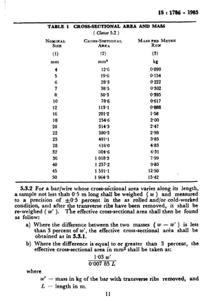
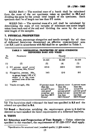
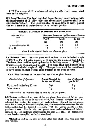
The document is the Indian Standard Specification for High Strength Deformed Steel Bars and Wires for Concrete Reinforcement. It outlines the requirements and testing procedures for steel reinforcement bars in three strength grades (Fe 415, Fe 500, Fe 550). Key points include:
- The standard covers manufacturing process, chemical composition limits, mechanical properties, and surface characteristics/deformations required for adequate bond with concrete.
- Steel bars must meet requirements for carbon, sulfur, phosphorus and mechanical properties depending on the specified strength grade.
- Deformations on the bar surface are specified as a minimum projected rib area to ensure adequate bond capacity.
- Bars can be manufactured by hot rolling followed by optional cooling/cold working
This document outlines British Standard BS 1881-116 from 1983 which provides the method for determining the compressive strength of concrete cubes. It describes the necessary apparatus, test specimens, procedures, type of failure, and calculations. The standard has been revised and amended since its original publication.
This document provides specifications for concrete batching and mixing plants. It outlines requirements for the plant components and systems. The plant must be capable of accurately batching and mixing materials like cement, fine and coarse aggregates, water, and admixtures. Storage bins are required for these materials. The batching equipment must weigh materials to within specified tolerances. The plant capacity must match the mixer size and be at least 100 cubic meters of concrete per hour.
1. The silt test was conducted to determine the amount of silt in a sand sample, which could reduce concrete strength if over 8%.
2. A 200ml sand sample was added to salt solution in a graduated cylinder. After settling for 3 hours, the silt layer was measured at 150ml and sand layer at 6ml.
3. The silt content was calculated at 4%, which is under the 8% limit and means the sand can be used for concrete projects.
This document provides design aids for reinforced concrete structures according to Indian Standard IS: 456-1978 Code of Practice for Plain and Reinforced Concrete. It includes charts, tables, and examples to aid in the design of flexural members (beams and slabs), compression members (columns), shear and torsion, development length and anchorage, working stress method designs, deflection calculations, and general reference tables. The design aids are intended to supplement an explanatory handbook on IS: 456-1978 by reducing design time for common structural elements using limit state design principles. Material properties, stress-strain relationships, and the basis for the design aids are explained.
IRJET- Partial Replacement of Sand with Sawdust in ConcreteIRJET Journal
This document presents research on partially replacing sand with sawdust in concrete mixtures. Sawdust was used to replace sand at 5%, 10%, 15%, 20%, and 25% by weight. Concrete cubes, beams, and cylinders were cast and tested for compressive, flexural, and split tensile strength at 7, 14, and 28 days. The results showed that compressive, flexural, and split tensile strength generally decreased as the sawdust replacement ratio increased. However, satisfactory strength results were obtained at a 5% sawdust replacement ratio for compressive and split tensile strength tests, and at a 10% replacement ratio for flexural strength tests. Using sawdust in concrete provides benefits like lighter weight
214 77 recommended practice for evaluation of strength tesMOHAMMED SABBAR
This document provides guidelines for analyzing the results of concrete strength tests using statistical methods. It discusses sources of variation in concrete strength, including materials properties, testing methods, and construction practices. Statistical analysis can help evaluate whether the concrete meets strength requirements while accounting for natural variability. The document recommends maintaining strict quality control, using random sampling, and following statistical procedures to properly interpret concrete strength test results.
The document provides instructions for conducting pull-out tests to determine the compressive strength of concrete. It states that pull-out tests should be confirmed to BS 1881 Part 207 and give a direct tensile strength value. It describes how inserts can be cast into wet concrete or positioned in hardened concrete using an under-reamed groove. When testing, at least four pull-out tests should be performed at each location and a loading rate of 0.5 ± 0.2 kN/s should be used for 25mm diameter inserts. The compressive strength can then be calculated from the direct tensile strength value obtained during testing.
The document outlines a method for determining the water absorption of concrete specimens cored from structures or precast components. It describes preparing three core specimens, drying them, weighing them before and after immersion in water, and calculating the water absorption percentage. Corrections are made to the measured absorption based on the length of the core specimen.
This lab report details procedures for determining the uniaxial compressive strength of rocks and concrete using Schmidt rebound hammers. Rebound hammers measure the elastic properties of materials by striking a spring-driven pin and measuring its rebound. Readings are used to estimate compressive strength by referencing conversion tables. Tests found that a quartzite rock sample had poor quality based on a rebound number equivalent to 41MPa of compressive strength, while a concrete sample had a good quality layer with a rebound number of 43MPa.
This standard practice provides two methods for selecting proportions for normal weight concrete, with or without chemical admixtures, pozzolanic materials, and slag. It describes how to take into account the requirements for workability, consistency, strength, and durability. Example calculations are shown for both methods. Appendices provide information on proportioning heavyweight concrete, mass concrete, and include metric conversions and example problems. The goal is to provide initial proportion designs that should then be verified through laboratory or field trials.
TMT Steel Bar is the main component in RCC that determines the strength of the structure.
The TMT Rebar are highly ductile in nature for which it helps the structure to hold during natural calamities such as an earthquake, Flood as well.
To know more in detail you can visit
https://shyamsteel.com/blogs/difference-between-fe500-and-fe500d-tmt-rebar/
Sp16 Civil Code Book (Civilqus.blogspot.com) Free DownloadGowtham Raja
This document provides design aids for reinforced concrete based on Indian Standard IS: 456-1978 Code of Practice for Plain and Reinforced Concrete. It contains charts and tables to help designers calculate flexural strength of beams, compressive strength of columns, shear strength, development length, deflection, and other parameters for reinforced concrete members. The design aids are presented in SI units and are intended to supplement an explanatory handbook on IS: 456-1978 by reducing design time. Assumptions made in developing the aids and an example problem are included to illustrate their use.
This document discusses the process of preparing and testing wet concrete. It describes concrete as a mixture of cement, sand, coarse aggregates, and water. It explains that the ratios of these materials and the water-cement ratio determine the concrete's properties. The document then covers conducting slump and cube tests to measure workability and compressive strength. It provides details on procedures, equipment, and interpreting results for each test. The goal is to produce quality concrete that meets the targeted strength values.
This document provides an overview of laboratory and field testing methods for rocks. It discusses index property tests such as unit weight, porosity, permeability, electrical resistivity, and sonic velocity that are used to characterize and classify rocks. It also describes mechanical property tests like unconfined compressive strength testing, triaxial testing, point load strength testing, and beam bending tests. Common field testing methods mentioned include pressuremeter testing, in-situ direct shear testing, and hydraulic fracturing. The document provides details on sample preparation, equipment used, procedures, and how to calculate and interpret results for different rock property tests.
Presentation on analysis and design of earthquake resistant multistorey educa...NripeshJha
This document appears to be a project report for the analysis and design of a 6-storey earthquake resistant educational building. It includes details of the building such as dimensions, materials used, and architectural plans. It describes the methodology used, which involved preliminary design, load calculation, structural analysis using ETABS, and detailed design of elements like slabs, columns, beams, staircases, foundations etc. It provides calculations for load combinations, base shear, and design of different structural components according to Indian codes and standards. The conclusion states that all codes for seismic analysis and composite loading were followed to design each member through ETABS analysis.
This document provides an overview of a project report on designing a multi-storied reinforced concrete building using ETABS software. The objectives are to analyze, design, and detail the structural components of the building. The methodology involves preparing CAD drawings, calculating loads, analyzing the structure, and designing and detailing structural elements. The building to be designed is a residential building with ground + 5 floors located in Chalikkavattom. Loads like dead, live, wind, and seismic loads will be calculated according to Indian codes and applied in the ETABS analysis model.
This is Report for Rebond hummer test it is usufull and respect report . used in work and good for student .non destractive test
and for any one like this branch
This document provides an overview of the design of steel structural members according to Eurocode standards, including columns, beams, and beam-columns. It discusses the main internal forces on members, the classification of cross-sections, and the approaches to checking the resistance of cross-sections and buckling resistance of members. It also provides an example calculation for the design of a steel column member under axial compression.
This document provides instructions for conducting a pull off test to determine the tensile strength of concrete. The test shall follow British Standard 1881 Part 207 and involves partially coring into the concrete and bonding a metal block to pull off from the surface using a hydraulic jack. Reinforcing steel should be avoided within the coring area or at a depth equal to the maximum aggregate size to obtain valid results. Six tests are typically needed at each test location.
This document summarizes British Standard BS 4483:1985 which specifies requirements for factory made welded steel fabric for reinforcing concrete. It outlines information to be provided by purchasers, permissible dimensions and tolerances, classification and testing requirements. Fabric must be manufactured from plain or deformed wire complying with other British Standards, with shear-resistant welded intersections tested to specified loads. The standard provides examples of common designated fabric types and their properties.
INVESTIGATION ON FLY ASH AS A PARTIAL CEMENT REPLACEMENT IN CONCRETESk Md Nayar
The use of Portland cement in concrete construction is under critical review due to high
amount of carbon dioxide gas released to the atmosphere during the production of cement. In
recent years, attempts to increase the utilization of fly ash to partially replace the use of Portland
cement in concrete are gathering momentum. Most of this by-product material is currently
dumped in landfills, creating a threat to the environment.
Fly ash based concrete is a ‘new’ material that does not need the presence of Portland
cement as a binder. Instead, the source of materials such as fly ash, that are rich in Silicon (Si)
and Aluminium (Al), are activated by alkaline liquids to produce the binder.
This project reports the details of development of the process of making fly ash-based
concrete. Due to the lack of knowledge and know-how of making of fly ash based concrete in the
published literature, this study adopted a rigorous trial and error process to develop the
technology of making, and to identify the salient parameters affecting the properties of fresh and
hardened concrete. As far as possible, the technology that is currently in use to manufacture and
testing of ordinary Portland cement concrete were used.
Fly ash was chosen as the basic material to be activated by the geopolimerization process
to be the concrete binder, to totally replace the use of Portland cement. The binder is the only
difference to the ordinary Portland cement concrete. To activate the Silicon and Aluminium
content in fly ash, a combination of sodium hydroxide solution and sodium silicate solution was
used.
Manufacturing process comprising material preparation, mixing, placing, compaction and
curing is reported in the thesis. Napthalene-based superplasticiser was found to be useful to
improve the workability of fresh fly ash-based concrete, as well as the addition of extra water.
The main parameters affecting the compressive strength of hardened fly ash-based concrete are
the curing temperature and curing time, The molar H2O-to-Na2O ratio, and mixing time.
Fresh fly ash-based concrete has been able to remain workable up to at least 120 minutes
without any sign of setting and without any degradation in the compressive strength. Providing a
rest period for fresh concrete after casting before the start of curing up to five days increased the
compressive strength of hardened concrete.
The elastic properties of hardened fly ash-based concrete, i,e. the modulus of elasticity,
the Poisson’s ratio, and the indirect tensile strength, are similar to those of ordinary Portland
cement concrete. The stress-strain relations of fly ash-based concrete fit well with the expression
developed for ordinary Portland cement concrete.
The document provides standards and limits for physical, chemical, and mechanical properties of aggregates used in concrete construction. It includes permissible limits for properties like grading, clay/organic content, absorption, specific gravity, shape, chlorides, sulphates, strength and abrasion resistance. Routine test methods and frequencies are also defined to ensure aggregate quality is monitored and maintained during concrete works. Requirements for stone pitching and gabion construction are briefly outlined.
This document discusses metakaolin, which is produced by calcining kaolin clay between 650-800°C. It has pozzolanic properties and can partially replace cement in high strength concrete. Metakaolin increases the strength and durability of concrete by reacting with calcium hydroxide to produce additional calcium-silicate-hydrate gel. It improves the physical and chemical properties of concrete, leading to applications in infrastructure like bridges, dams, and buildings where high strength and durability are important.
This document discusses steel fibre reinforced concrete (SFRC). It begins with an introduction to fibre reinforced concrete and why fibres are added to concrete to improve properties. It then classifies fibre types and focuses on SFRC, describing steel fibre types, composition, mixing, and improved properties like tensile strength and impact resistance. Limitations and applications are covered, along with conclusions and references.
This document is a handbook on reinforcement and detailing produced by the Bureau of Indian Standards. It provides information on steel for reinforcement, including specifications for mild steel, medium tensile steel, high strength deformed steel bars, and hard-drawn steel wire fabric. It outlines the physical and mechanical properties required for different steel types, as well as tolerances for dimensions. The handbook serves as a companion to other documents on reinforced concrete, providing guidance on steel properties and specifications to inform proper reinforcement detailing.
EXPERIMENTAL STUDY OF STRENGTH BEHAVIOUR ON CEMENT MORTAR Chandan Kumar.D
EXPERIMENTAL STUDY OF STRENGTH BEHAVIOUR ON CEMENT MORTAR BY PARTIAL REPLACEMENT OF CEMENT WITH GRANITE WASTE, ALUMINIUM HYDROXIDE AND FULLY REPLACEMENT OF FINE AGGREGATE BY CRUSHED STONE DUST
This document is the Indian Standard Specification for plain hard-drawn steel wire for prestressed concrete. It outlines the requirements for the manufacture, supply, and testing of steel wire used in prestressed concrete. Some key points:
- The wire must be cold drawn from steel produced by various processes like open hearth or basic oxygen process. The steel composition limits sulfur and phosphorus.
- Wires have nominal diameters between 2.5-8 mm. Tolerances on diameter are specified.
- Physical requirements include minimum tensile strengths specified for each diameter wire. Wire must also meet elongation, relaxation, and stress corrosion requirements.
- Manufacturing process involves cold drawing rods to size, stress relie
This document provides specifications for hard-drawn steel wire fabric used for concrete reinforcement. It defines key terms, specifies the material and manufacturing requirements, and sets tolerances. There are two types of fabric - oblong and square mesh. Dimensions include mesh size, weight, and wire diameters. Sheets and rolls have specified widths and lengths to fit construction modules. Mass is calculated based on the steel density, and actual mass is determined by weighing samples.
This document provides the specifications for plain hard drawn steel wire intended for use in prestressed concrete. It outlines the following key points:
- The wire shall be cold drawn from steel produced via various processes to contain less than 0.05% sulfur and phosphorus.
- Nominal diameters shall be 3.0 mm, 4.0 mm, or 5.0 mm within specified tolerances.
- The wire must meet minimum tensile strength requirements and have a proof stress of at least 75% of the tensile strength.
- It must pass reverse bend tests without fracturing to demonstrate adequate ductility.
The document also describes manufacturing requirements, permissible defects, testing methods and sampling procedures to
The document is the Indian Standard specification for hard-drawn steel wire for use as reinforcement in concrete. It outlines the requirements and tests for the wire including:
- The wire must be cold-drawn from mild steel and have less than 0.05% sulfur and phosphorus content.
- Wire sizes range from 2.65 to 10 mm in diameter.
- Tolerances on diameter are +/- 1%.
- Tensile strength must be at least 570 MPa, yield strength must be at least 480 MPa, and elongation must be at least 7.3%.
- Wire must pass a reverse bend test without fracturing.
- Testing requirements include tensile tests and bend
This document provides the specification for high tensile steel bars used in prestressed concrete. It outlines the requirements for the manufacture, chemical composition, sizes, tolerances, physical properties, testing procedures, sampling methods, and criteria for conformity of the steel bars. The bars must be made through specific steel manufacturing processes and have certain chemical compositions. They are tested to ensure they meet the specified requirements for properties like tensile strength, proof stress, and elongation.
This document provides the specification for high tensile steel bars used in prestressed concrete. It outlines the requirements for the manufacture, chemical composition, sizes, tolerances, physical properties including tensile strength, proof stress and elongation. It also describes the testing methods for these properties, including tensile testing and constant strain relaxation testing. Finally, it specifies the sampling and criteria for conformity, delivery, inspection, and required testing facilities.
This document provides guidelines for welding mild steel plain and deformed bars used for reinforced concrete construction. It specifies various welding processes that can be used, including flash butt welding, manual metal-arc welding, oxy-acetylene welding, gas pressure welding, and thermit welding. It also provides requirements for welding equipment, electrodes, filler rods, welder qualifications, joint preparation, and inspection of welds. The guidelines are intended to help ensure welds meet minimum strength requirements for reinforced concrete applications.
This document outlines standards for mild steel and medium tensile steel bars used for concrete reinforcement. It specifies requirements for chemical composition, sizes, tolerances, defects, and physical properties including ultimate tensile strength, yield strength, and elongation. Tests include tensile testing and bend testing according to described procedures. Bars are classified into mild steel Grade I and II, and medium tensile steel, with specified minimum mechanical property requirements for each type and size.
This document is the Indian Standard for high strength deformed steel bars and wires used for concrete reinforcement. It specifies the requirements for various grades of reinforcing bars and wires, including their chemical composition, manufacturing process, mechanical properties, and bonding characteristics. The standard allows for bars and wires produced via various manufacturing routes, including hot rolling with or without controlled cooling, and cold working. It defines terms, sets limits for chemical composition, and provides requirements for mechanical properties, deformation patterns, and bond strength.
This document provides the specifications for precast reinforced concrete street lighting poles. It outlines the materials, design considerations, testing requirements and more. Some key points:
- Poles must be a minimum of 5.2m in length, with mounting heights of at least 4m and planting depths of at least 1.2m.
- Concrete grade shall be at minimum M20. Reinforcement can be mild steel, medium tensile steel or deformed steel bars.
- Poles shall be designed to resist a maximum bending moment from loads like wind pressure and the weight of fixtures applied 600mm below the light source.
- Testing includes determining the ultimate transverse load at which the pole fails under a load
This document provides information on the Indian Standard method for the Brinell hardness test for metallic materials. It outlines the key aspects of the test including:
- The test uses a hardened steel or hard metal ball of a specified diameter that is pressed into the material's surface under a defined load.
- The Brinell hardness value is determined based on the diameter of the indentation left in the surface after removal of the load.
- The standard provides details on apparatus, test pieces, procedures, symbols and designations, and test forces to be used for different materials.
This document provides specifications for precast concrete cable covers. It classifies cable covers based on whether they are reinforced or unreinforced, and whether they have a peaked or flat design. Reinforced concrete covers with a peaked design are recommended for high voltage cables of 22kV and above. Unreinforced peaked covers are for voltages above 1kV but below 22kV. Unreinforced flat covers are used for cables up to and including 1kV. The document specifies requirements for materials, dimensions, reinforcement, and markings for the different types and classes of precast concrete cable covers.
The document is an Indian Standard code of practice for installing joints in concrete pavements. It provides definitions for different types of joints and pavements. It outlines design considerations for the layout and details of transverse and longitudinal joints. It specifies requirements for materials used in joints like joint filler, sealing compounds, and dowel bars. It describes the purpose and details of transverse expansion joints, contraction joints, and construction joints. The code aims to provide guidance on installing joints to control cracking and allow for movement in concrete pavements.
IS 2062(2011) Seventh Revision: Hot rolled medium and high tensile structural...rajguptanitw
This Indian Standard (Seventh Revision) was adopted by the Bureau of Indian Standards, after the draft
finalized by the Wrought Steel Products Sectional Committee had been approved by the Metallurgical
Engineering Division Council.
This standard was first published in 1962 and revised in 1969, 1975, 1984, 1992, 1999 and 2006. While reviewing
this standard, in the light of experience gained during these years, the Committee decided to revise it to bring
in line with the present practices being followed by the Indian steel industry, both in the integrated as well as
secondary sectors. The Committee further decided to harmonize the standard with the overseas standards on
carbon-manganese and high strength low alloy (HSLA) of structural steels.
In this revision, the following changes have been made:
a) Title has been modified and the word ‘low’ has been deleted, keeping in view the grades of steel
contained in the standard. Requirements of low tensile structural steel are covered in IS 15911 : 2010
‘Structural steel (ordinary quality) — Specification’.
b) Amendment No. 1 has been incorporated with suitable modifications.
c) Number of basic grades has been changed to nine. A new grade of E275, in line with European Standard,
has been incorporated to take care of the requirements of medium tensile structural steels in the
construction segment. Moreover, for each grade two to four sub-qualities have been introduced,
depending upon the grade, where sub-qualities A, BR, B0 and C, in line with other international standards,
indicate the mode of killing and impact test requirements.
d) The clause on ‘Manufacture’ has been modified, where the scope is suitably widened to include
different steel making and rolling practices in vogue.
e) Silicon content of semi-killed steel has been clearly specified.
For all the tests specified in this standard (chemical/physical/others), the method as specified in relevant
ISO Standard may also be followed as an alternate method.
While revising the standard, assistance has been derived from the following international specifications:
ASTM A 36 : 2008 Specification for structural steel
ASTM A 572 : 2007 Specification for high-strength low-alloy columbium-vanadium structural steel
EN 10025-2 : 2004 Hot rolled products of structural steels
The composition of the Committee responsible for the formulation of this standard is given in Annex A.
For the purpose of deciding whether a particular requirement of this standard is complied with, the final value,
observed or calculated, expressing the result of a test or analysis, shall be rounded off in accordance with
IS 2 : 1960 ‘Rules for rounding off numerical values (revised)’. The number of significant places retained in
the rounded off value should be the same as that of the specified value in this standard.
This document is the Indian Standard for steel tubes, tubulars, and other steel pipe fittings. It outlines requirements for various steel pipe fittings including sockets, tubulars, elbows, tees, crosses, and other welded or seamless fittings. The standard specifies material composition limits, manufacturing processes, dimensional requirements for different fitting types, and testing methods. It is intended to ensure quality and consistency for steel pipe fittings used in water, gas, air and steam applications in India.
This document provides a code of practice for laying concrete pipes. It includes methods for calculating loads on pipes according to installation conditions and provides corresponding load factors. The purpose is to relate the loads on concrete pipes installed under various conditions to the test strength of the pipe, through appropriate load factors. The document defines key terms, outlines symbols used in calculations, and describes methods to calculate vertical loads on pipes from earth fill material, concentrated loads, and distributed loads. It is intended to be used with other standards for concrete pipes to help ensure pipes are not subjected to loads exceeding their design strength.
This document provides the specification for reinforced concrete fence posts according to Indian Standard IS:4996-1984. It outlines the materials, manufacturing process, shape and dimensions, and fixing of fencing wires for reinforced concrete fence posts. Some key points include:
- Cement, water, aggregates and reinforcement materials must meet standards specified.
- Posts are to be manufactured through mixing, placing and compacting concrete to be dense and free of voids.
- Reinforcement is to be properly positioned and anchored with minimum concrete cover requirements.
- Posts must cure for a minimum of 7 days and achieve a strength threshold before handling.
- Dimensions and tolerances are provided, with recommendations for line, strainer
This document outlines specifications for precast concrete coping blocks. It specifies requirements for materials used in manufacturing coping blocks such as cement, aggregates, additives, and concrete strength. It also provides dimensions and tolerances for the cross-section and length of coping blocks. The specifications are intended to ensure coping blocks effectively prevent water penetration, direct water away from walls, resist displacement forces, allow for movement, and provide durability.
The document provides specifications for precast prestressed concrete street lighting poles. It outlines requirements for materials, design, testing, and other technical details. Key points include:
- It specifies requirements for cement, aggregates, reinforcement, concrete, and admixtures to be used in manufacturing the poles.
- Design specifications include minimum pole length, depth of planting, distances from luminaire to light source, and standard outreach lengths. Poles must be designed not to fail due to compression of concrete.
- Technical details covered include tolerances on dimensions, sampling and inspection procedures, marking requirements, and other quality control aspects.
This document provides a code of practice for the construction of autoclaved cellular concrete block masonry. It outlines materials and design considerations for constructing load-bearing and non-load bearing walls using these blocks. The document discusses block requirements, mortar mixes, wall thickness, bracing, and modular coordination. It aims to help builders properly use this type of masonry and ensure structural safety and avoidance of cracks.
28-5.21 Company Profile of Pyrmaid structural consultant.pptxBoopathi Yoganathan
Pyramid Structural Consultant provides structural design, building approval, and construction services. They have a team of experienced engineers and workers who use software like AutoCAD and STAAD to complete structural designs for RCC and steel buildings. Notable projects include the design of a G+1 residential building in Namakkal. They are located in Puduchatram, Namakkal and can be found on LinkedIn and Facebook.
This document provides a bonafide certificate for a project report on the study of mechanical properties of eco-friendly economic concrete. It certifies that the project was conducted by three students, M.Vineeth, Y.Boopathi, and P.Murali, in partial fulfillment of their Bachelor of Engineering degree from Kongu Engineering College. The project investigated replacing natural aggregates with steel slag aggregates and M-sand to produce more sustainable concrete. Tests were conducted to determine the compressive strength, split tensile strength, modulus of rupture, and modulus of elasticity of concrete mixes with varying replacement levels.
The document describes an experimental investigation into the properties of concrete with different replacement percentages of natural aggregates with manufactured sand and steel slag. The methodology involves collecting cement, fine aggregates (natural sand and m-sand), coarse aggregates, and steel slag. The mix design for M20 grade concrete is calculated and concrete specimens are cast. The specimens are cured and then tested to determine their mechanical properties. The results are compared to those of conventional concrete to evaluate the suitability of manufactured sand and steel slag as partial replacements for natural aggregates in concrete.
The document discusses two methods for mesh refinement - the p-method and h-method. The p-method increases the order of the polynomial used in the finite element model, allowing for more accurate results without changing the mesh. The h-method reduces the size of elements to create a finer mesh, better approximating the real solution in areas of high stress gradients. Both methods aim to improve the accuracy of finite element analysis results, with the p-method doing so without requiring changes to the mesh.
This document provides guidance on using epoxy injection to repair cracks in concrete structures. The method involves drilling holes along cracks, injecting epoxy under pressure, and allowing it to seep into the cracks. It can repair cracks as small as 0.002 inches. Epoxy injection requires skilled workers and specialized equipment. While it can effectively repair cracks temporarily, the underlying issues causing the cracks may remain if not addressed.
An embedded system is a dedicated computer system that performs specific tasks. An important application of embedded systems is anti-lock braking systems (ABS) in automobiles. ABS uses sensors and electronic control modules to monitor wheel speed and automatically modulate brake pressure to prevent wheel lockup and maintain steering control during emergency braking. By preventing skidding, ABS can help drivers stop more safely and shorten stopping distances on wet or slippery surfaces compared to standard brakes. ABS works by pulsing the brakes rapidly when it detects a wheel is about to lock up, which allows the wheel to continue turning and maintaining traction with the road.
This document discusses past earthquakes in India and retrofitting techniques for masonry structures. It summarizes the 2004 Indian Ocean earthquake and tsunami, which had a magnitude of 9.1-9.3 making it one of the largest ever recorded. Over 230,000 people were killed across 14 countries by the resulting tsunamis. The document then discusses failure modes of confined masonry walls and retrofitting techniques to improve seismic resistance, including adding horizontal reinforcement, improving wall density and tie columns. Key factors for seismic resistance of confined masonry structures are also summarized.
The document provides guidelines for selecting, splicing, installing, and protecting open cable ends for resistance-type measuring devices in concrete and masonry dams. It discusses cable specifications, approved splicing methods including vulcanized rubber splices, rubber sleeve covering, and self-bonding tape. It also covers cable and conduit selection, including choosing the proper conduit size based on the number and size of cables to be run. Proper installation techniques are outlined to protect cable runs within concrete structures.
This document provides information on an Indian Standard (IS) for a unified nomenclature of workmen for civil engineering. It was adopted in 1982 by the Indian Standards Institution Construction Management Sectional Committee. The standard aims to unify the different names used for workmen engaged in civil engineering works across India. It then lists the unified nomenclature for various types of workmen and for carts/animals commonly used in civil engineering works.
This document provides details on the design and construction of floors and roofs using precast reinforced or prestressed concrete ribbed or cored slab units. It specifies dimensions for the precast units, including widths up to 3000mm for ribbed units and 2100mm for cored units. It also provides requirements for material strengths, structural design considerations, and loads to be accounted for in design according to other relevant Indian Standards.
This document provides definitions for key terms related to concrete monolith structures used in port and harbour construction. It defines elements like the bottom plug, cutting edge, deck slab, dewatering, fascia wall, filling, kentledge, kerb, and monolith. A monolith is a large hollow rectangular or circular foundation sunk as an open caisson through various soil strata until reaching the desired founding level, at which point the bottom is plugged with concrete.
The document provides specifications for an apparatus used to measure the length change of hardened cement paste, mortar, and concrete. It describes the construction, dimensions, materials, and markings required for a length comparator, which uses a micrometer to measure the change in length of specimens against a reference bar. The length comparator consists of an adjustable frame that holds either a screw or dial micrometer and allows measurement of specimens of different lengths.
This document provides the code of practice for the design and construction of conical and hyperbolic paraboloidal shell foundations. It discusses the preliminary design considerations for shell foundations, including determining the soil design to proportion the foundation dimensions based on allowable bearing pressure and net loading intensity, as well as the structural design of the shell. It also provides figures illustrating reinforcement details for conical and hyperbolic paraboloidal shell foundations. The code covers the relevant terminology and information needed for design, and notes the membrane analysis approach is commonly used for structural design of shell foundations.
This document provides guidelines for designing drainage systems for earth and rockfill dams. It discusses key considerations like controlling pore pressures, internal erosion, and piping. The guidelines cover selecting appropriate drainage features based on the dam type and materials. Features discussed include inclined/vertical filters, horizontal filters, longitudinal and cross drains, transition zones, rock toes, and toe drains. Filter material criteria and design procedures are also outlined.
This document provides recommendations for welding cold-worked steel bars used for reinforced concrete construction according to Indian Standard IS 9417. It summarizes the key welding processes that can be used including flash butt welding, shielded metal arc welding, and gas pressure welding. For each process, it outlines preparation of the bars, selection of electrodes, welding procedures, and safety requirements. Diagrams are provided to illustrate edge preparation and sequences for multi-run butt welding and lap welding joints.
This document provides guidelines for lime concrete lining of canals. It discusses materials used for lime concrete lining such as lime, sand, coarse aggregate and water. It also discusses preparation of subgrade for different soil types including expansive soils, rock and earth. Compaction methods are provided for different soil types. The document also discusses laying of concrete lining and provides specifications for lime concrete mix such as minimum compressive and flexural strength.
This document provides guidelines for structural design of cut and cover concrete conduits meant for transporting water. It outlines various installation conditions for underground conduits and describes how to calculate design loads from backfill pressure, internal/external water pressure, and concentrated surface loads. Design loads include vertical and lateral pressure from backfill based on fill material properties, hydrostatic pressure from water surcharge, and dispersed point loads accounting for fill height and conduit geometry. The conduit is to be designed for the most unfavorable combination of these loads. Recommended fill material properties and methods for load and stress analysis are also provided.
This document provides guidelines for installing and observing cross arms to measure internal vertical movement in earth dams. It describes the components of the mechanical cross arm installation including the base extension, cross arm units, spacer sections, and top section. It provides details on installing each component as the dam is constructed in rock-free or rocky soils. Observation involves using a measuring torpedo attached to a steel tape or cable to take settlement readings from the installed cross arm system.
This document provides guidelines for instrumentation of concrete and masonry dams. It outlines obligatory and optional measurements for dams, including uplift pressure, seepage, temperature, and displacement. Obligatory measurements include uplift pressure, seepage, temperature inside the dam, and displacement measurements using plumb lines or other methods. Optional measurements that may provide additional insights include stress, strain, pore pressure, and seismicity measurements. The document describes different types of measurements in detail and how they can be used to monitor dam performance and safety over time.
This document provides guidelines for selecting measurement instruments and their locations for monitoring earth and rockfill dams. It describes various types of measurements needed, including pore pressure, movements, seepage, strains/stresses, and dynamic loads from earthquakes. Planning the instrumentation system is important to ensure required data is obtained during construction and the dam's lifetime. The document discusses different instruments for measuring vertical and horizontal movements, such as surface markers, cross-arm installations, hydraulic devices, magnetic probes, and inclinometers.
ISO/IEC 27001, ISO/IEC 42001, and GDPR: Best Practices for Implementation and...PECB
Denis is a dynamic and results-driven Chief Information Officer (CIO) with a distinguished career spanning information systems analysis and technical project management. With a proven track record of spearheading the design and delivery of cutting-edge Information Management solutions, he has consistently elevated business operations, streamlined reporting functions, and maximized process efficiency.
Certified as an ISO/IEC 27001: Information Security Management Systems (ISMS) Lead Implementer, Data Protection Officer, and Cyber Risks Analyst, Denis brings a heightened focus on data security, privacy, and cyber resilience to every endeavor.
His expertise extends across a diverse spectrum of reporting, database, and web development applications, underpinned by an exceptional grasp of data storage and virtualization technologies. His proficiency in application testing, database administration, and data cleansing ensures seamless execution of complex projects.
What sets Denis apart is his comprehensive understanding of Business and Systems Analysis technologies, honed through involvement in all phases of the Software Development Lifecycle (SDLC). From meticulous requirements gathering to precise analysis, innovative design, rigorous development, thorough testing, and successful implementation, he has consistently delivered exceptional results.
Throughout his career, he has taken on multifaceted roles, from leading technical project management teams to owning solutions that drive operational excellence. His conscientious and proactive approach is unwavering, whether he is working independently or collaboratively within a team. His ability to connect with colleagues on a personal level underscores his commitment to fostering a harmonious and productive workplace environment.
Date: May 29, 2024
Tags: Information Security, ISO/IEC 27001, ISO/IEC 42001, Artificial Intelligence, GDPR
-------------------------------------------------------------------------------
Find out more about ISO training and certification services
Training: ISO/IEC 27001 Information Security Management System - EN | PECB
ISO/IEC 42001 Artificial Intelligence Management System - EN | PECB
General Data Protection Regulation (GDPR) - Training Courses - EN | PECB
Webinars: https://pecb.com/webinars
Article: https://pecb.com/article
-------------------------------------------------------------------------------
For more information about PECB:
Website: https://pecb.com/
LinkedIn: https://www.linkedin.com/company/pecb/
Facebook: https://www.facebook.com/PECBInternational/
Slideshare: http://www.slideshare.net/PECBCERTIFICATION
हिंदी वर्णमाला पीपीटी, hindi alphabet PPT presentation, hindi varnamala PPT, Hindi Varnamala pdf, हिंदी स्वर, हिंदी व्यंजन, sikhiye hindi varnmala, dr. mulla adam ali, hindi language and literature, hindi alphabet with drawing, hindi alphabet pdf, hindi varnamala for childrens, hindi language, hindi varnamala practice for kids, https://www.drmullaadamali.com
LAND USE LAND COVER AND NDVI OF MIRZAPUR DISTRICT, UPRAHUL
This Dissertation explores the particular circumstances of Mirzapur, a region located in the
core of India. Mirzapur, with its varied terrains and abundant biodiversity, offers an optimal
environment for investigating the changes in vegetation cover dynamics. Our study utilizes
advanced technologies such as GIS (Geographic Information Systems) and Remote sensing to
analyze the transformations that have taken place over the course of a decade.
The complex relationship between human activities and the environment has been the focus
of extensive research and worry. As the global community grapples with swift urbanization,
population expansion, and economic progress, the effects on natural ecosystems are becoming
more evident. A crucial element of this impact is the alteration of vegetation cover, which plays a
significant role in maintaining the ecological equilibrium of our planet.Land serves as the foundation for all human activities and provides the necessary materials for
these activities. As the most crucial natural resource, its utilization by humans results in different
'Land uses,' which are determined by both human activities and the physical characteristics of the
land.
The utilization of land is impacted by human needs and environmental factors. In countries
like India, rapid population growth and the emphasis on extensive resource exploitation can lead
to significant land degradation, adversely affecting the region's land cover.
Therefore, human intervention has significantly influenced land use patterns over many
centuries, evolving its structure over time and space. In the present era, these changes have
accelerated due to factors such as agriculture and urbanization. Information regarding land use and
cover is essential for various planning and management tasks related to the Earth's surface,
providing crucial environmental data for scientific, resource management, policy purposes, and
diverse human activities.
Accurate understanding of land use and cover is imperative for the development planning
of any area. Consequently, a wide range of professionals, including earth system scientists, land
and water managers, and urban planners, are interested in obtaining data on land use and cover
changes, conversion trends, and other related patterns. The spatial dimensions of land use and
cover support policymakers and scientists in making well-informed decisions, as alterations in
these patterns indicate shifts in economic and social conditions. Monitoring such changes with the
help of Advanced technologies like Remote Sensing and Geographic Information Systems is
crucial for coordinated efforts across different administrative levels. Advanced technologies like
Remote Sensing and Geographic Information Systems
9
Changes in vegetation cover refer to variations in the distribution, composition, and overall
structure of plant communities across different temporal and spatial scales. These changes can
occur natural.
How to Setup Warehouse & Location in Odoo 17 InventoryCeline George
In this slide, we'll explore how to set up warehouses and locations in Odoo 17 Inventory. This will help us manage our stock effectively, track inventory levels, and streamline warehouse operations.
Beyond Degrees - Empowering the Workforce in the Context of Skills-First.pptxEduSkills OECD
Iván Bornacelly, Policy Analyst at the OECD Centre for Skills, OECD, presents at the webinar 'Tackling job market gaps with a skills-first approach' on 12 June 2024
1. Gr5
IS :1786 - 1985
Superseding IS : 1139-1966
( RentTimed 1990 )
Indian Standard
SPECIFICATION FOR
HIGH STRENGTH DEFORMED STEEL
BARS AND WIRES FOR CONCRETE
REINFORCEMENT
( Third Revision)
Third Reprint APRIL 1992
UDC 669.14.018.26-422.2:666.982.24
@ Cojpvi~ht 1985
BUREAU OF INDIAN STANDARDS
MANAK BHAVAN. 9 BAHADUR SHAH ZAFAR MARG
NEW DELHI 1loooZ
October 1985
2. IS :1786-1985
Superseding IS : 1139-1966
hdiun Standard
SPECIFICATION FOR
HIGH STRENGTH DEFORMED STEEL
BARS AND WIRES FOR CONCRETE
REINFORCEMENT
( Third Revision)
Joint Sectional Committee for Concrete Reinforcement, BSMDC 8
Chairman Representing
SHRI G. S. Rao Central Public Works Department, New Delhi
Mmbsrs
SUPEKLNTENDING ENGINECI: ( CD0 ) ( Allernate to
Shri G. S. Rao )
Bn~o S. V. ABITYANKAIQ Engineer-in-Chief’s Branch, Army Headquarters,
New Delhi
Dn J. L. AJMANI The Tata Iron & Steel Co Ltd, Jamshedpur
SHRI A. N. MITICA ( Altcrnatc )
DR ANIL KUMAR Cement Research Institute of India, New Delhi
SHRI S. BANERJEE Steel Re-rolling Mills Association of India, Calcutta
SHILIS. N. CEANDA Metallurgical & Engineering Consultants India Ltd,
Ranchi
SHRI R. D. CHOUDHARY ( Alternate )
SHRI S. P. CHAKRABORT~ Ministry of Shipping and Transport ( Roads Wing )
CHIEF ENOI~ER ( MHPD ) Irrigation Department, Government of Punjab,
Chandigarh
DIRECTOR ( PP ) ( TDO ) ( Alternate ).
DEPUTY DIRECTOR STANDARDS Research, Designs & Standards Organization,
( B&S ) CB Lucknow
ASSISTANT DIRECTOR, STAEJIJARUB
( B&S ) CB ( Alternate )
Sam c. DASoUPT_4 Bhilai Steel Plant ( Steel Authority of India L!d ),
Bhilai
SHRI S. GOPALAN ( Alternate )
SRRI D. I. DESAI
SHRI A. L. BHATIA ( Alfernatc )
Gammon India Ltd, Bombay
SHRI M. R. DOOTOR Special Steels Ltd, Bombay
SHRI V. C. TRICKUR ( Alternafc )
( Continued on page 2 )
@ Copyight 1985
BUREAU OF INDIAN STANDARDS
This publication is protected under the I&an Copyrighr AC: ( XIV of 1957 ) and
reproduction in whole or in part by any means except with written permkion of the
publkhar shall be deemed to be an infringement of copyright under the raid Act.
3. IS t1786- 1985
( Continued pornpage1 )
Members
&RI V. K. GHANEKAR
Repsenting
Stru;tu;;uzngineering Research Centre ( CSIR ),
SHRI D. S. PRAI~ASHRAO ( Alfrraats )
SHRI P. K. GUPTA National Metallurgical Laboratory ( CSIR ),
Jamshedpur -
SFIRI N. C. JAIN Stup Consultants Ltd, Bombay
SHRI M. C. TANDON ( Alfcrnafc )
SRRI M. P. JASTJJA Research & Development Centre for Iron & Steel
( Steel Authority of India Ltd ), Ranchi
SKRI S. Y. KHAN Killick Nixon Ltd, Bombay
SRRI P. S. VENKAT ( Alternate )
SHRI H. N. KRISHNA MURTHY Tor Steel Research Foundation in India, Calcutta
DR C. S. VISWANATHA ( Ahmate )
SERI S. N. PAL M. N: Dastur & Co Pvt Ltd, Calcutta
SHRI SALIL ROY ( Alternate )
SERI B. K. PANTRAKY Hindustan Construction Co Ltd, Bombay
SHRI P. V. NAIK ( Alternate )
SHRI K. K. RAO Usha Ismal Ltd, Ranchi
SHRI RAXESH KORLI ( Alternate )
REPRESENTATIVE Public Works Department, Government of Uttar
Pradesh, Lucknow
SHRI T. SEN IRC Steels Ltd, Calcutta
SHRI SHIRISR H. SHAH Tensile Steel Ltd, Bombay
SHRI M. S. PATHAR ( Alternate )
SHRI C. N. SRINIVASAN C. R. Narayana Rao, Madras
SHRI C. N. RA~HAVENDRAN ( Alhrnats )
$IKRIK. S. SRINIVASAN National Buildings Organization, New Delhi
SHRI A. K. LAL ( Altematc )
SHRI ZAO~ARIA GEORQE StrupaTrlasEngineering Research Centre ( CSIR ),
SHRI G. V. SURYAKUMAR ( Altematr )
SHXI G. RA’XAN Director General, IS1 ( Ex-oficio Member )
Director ( Civ Engg)
Secretary
SHRI N. C. BANDYOPADHYAY
Deputy Director ( Civ Engg ), IS1
Ad hoc Panel for Review of Standards on Deformed Steel Bars for
Concrete Reinforcement, BSMDC 8 : AP
Convener
SHRI JOSE KURIAN Central Public Works Department, New Delhi
Members
DR P. C. CHOWDHARY Tor Steel Research Foundation in India, Bangalore
DR T. MTJKHERJEE The Tata Iron and Steel Co Ltd, Jamshedpur.
SHRI S. C. MOHANTY ( Altamatr )
SHRI A. G. RAXA RAO Bhil$S~el Plant ( Steel Authority of India Ltd ),
2
4. IS:1786 -1985
Indian Standard
SPECIFICATION FOR
HIGH STRENGTH DEFORMED STEEL
BARS AND WIRES FOR CONCRETE
REINFORCEMENT
( Third Revision)
0. FOREWORD
0.1 This Indian Standard ( Third Revision ) was adopted by the Indian
Standards Institution on 1 May 1985, after the draft finalized by the
Joint Sectional Committee for Concrete Reinforcement had been
approved by the Civil Engineering Division Council.
0.2 Deformed bars for concrete ‘reinforcement are being produced in
the country for many years, the main processes being hot rolling or hot
rolling followed by cold twisting. In the past decade there has been an
increasing demand for higher strength deformed bars ( 415 N/mmz, Min,
yield strength/O.2 percent proof stress being the most common j. This
high yield strength was being first achieved by raising carbon and
manganese and to a great extent by cold twisting. In addition IO this,
there has been considerable demand for larger diameter bars with
similar strength, elongation, weldability and bendability as that of small
size bars. Along with this, the;e is also a need for these steel bars to
be welded and fabricated on the site easily. For this, strength and
ductility have to be achieved at the lowest possible carbon content.
0.2.1 Technological advances during the last few years in the field of
deformed bar production have helped in meeting all the above require-
ments together. Microalloying with Nb, V, Ti and B, in combination
or individually, and thermomechanical treatment process are worth
mentioning in this field. With these two processes higher strength values
could be achieved at low carbon levels even in large diameter bars.
0.3 Two Indian Standard specifications, namely, IS : 1139-1966
‘Specification for hot rolled mild steel, medium tensile steel and high yield
strength steel deformed bars for concrete reinforcement ( revised )’ and
IS : 1786-1979 ‘Specification for cold-worked steel high strength deformed
bars for concrete reinforcement r second revision )’ covered deformed bars
3
5. IS : 1786 - 1985
for concrete reinforcement, To take advantage of the technological
changes, it is thought necessary to merge these two specifications giving
:IEE? option of the manufacturing process to the producers so as to meet
nlZ the requirements of the specification. Hence the revision of IS : 1139-
1966 and IS : 1786-1979 has been prepared combining them into a
single specification with modified designation and title. In this revision
the requirements of chemical composition have been modified, a new
strength grade Fe 550 has been introduced, Fe 250 and Fe 350 strength
grades have been deleted, requirements of modified bar geometry have
been made applicable to hot-rolled bars in addition to cold-worked bars;
further 4, 5 and 7 mm nominal sizes have been introduced; and a few
other changes found necessary as a result of experience gained have been
incorporated.
8.4 For the purpo.qe of deciding whether a particular requirement of
this standard is complied with, the final value, observed or calculated,
expressing the result of a test or analysis, shall be rounded off in accor-
dance with IS : 2-1960*. The number of significant places retained in
the rounded off value shoilld be the same as that of the specified value
in this standard.
1. SCOPE
I.1 This standard covers the requirements of deformed steel bars and
wires for use as reinforcement in concrete, in the following three strength
grades:
a) Fe 415,
b) Fe 500, and
c) Fe 550.
No~r~ - The figures following the svmbol Fe indicates the specified minimum 0’2
*,Jercent proof stress or yield stress in N/mm*.
2, TERMINOLOGY
2.0 For the purpose of this standard, the following definitions shall apply.
-4.1 Biatch - Any quantity of hars,‘wires of same size and grade whether
.I ~oilx or bundles presented for examination and test at one time.
f’1.2 Bundle - Two or more coils or a number of lengths properly
ijound together.
-- ..---
*Rules for rounding off numerical values ( revised).
4
6. IS t 1786 - 19S5
2.3 Elongation - The increase in length of a tensile test piece under
stress. The elongation at fracture is conventionally expressed as a
percentage of the original gauge length of a standard test piece.
2.4 Longitudinal Rib - A rib of uniform cross-section, parallel to the
axis of the bar/wire ( before cold-working, if any ).
2.5 Nominal Diameter or Size - The diameter of a plain round
bar/wire having the same mass per metre length as the deformed bar/
wire.
2.6 Nominal Perimeter of a Deformed Bar/Wire - 3.14 times
the nominal diameter.
2.7 Nominal Mass - The mass of the bar/wire of nominal diameter
and of density 8887 85 kg/mm2 per metre run.
2.8 0.2 Percent Proof Stress - The stress at which a non-proportional
elongation equal to 0.2 percent of the orginal gauge length takes place.
2.9 Tensile Strength - The maximum load reached in a tensile test
divided by the effective cross-rectional area of the gauge length portion
of the test piece. Also termed as ultimate tensile stress.
2.10 Transverse Rib - Any rib on the surface of a bar,wire other
than a longitudinal rib.
2.11 Yield Stress - Stress ( that is, load per unit cross-sectional area )
at which elongation first occurs in the test piece without increasing the
load during tensile test. In the case of steels with no such definite yield
point, proof stress shall be applicable.
3. MANUFACTURE AND CHEMICAL COMPOSITION
3.1 Steel shall be manufactured by the open-hearth, electric, duplex,
basic-oxygen, or a combination of these processes. In case any other
process is employed by the manufacturer, prior approval of the pur-
chaser should be obtained.
3.1.1 Steel shall be supplied semi-killed or killed.
3.1.2 The bars/wires shall be manufactured from properly identified
heats of mould cast, continuously cast steel or rolled semis.
3.1.3 The steel bars/wires for concrete reinforcement shall be manu-
factured by the process of hot-rolling. It may be followed by a suitable
method of cooling and/or cold working.
5
7. IS:1788 - 1985
5.2 Chemical Composition - The ladle analysis of steel when made
as per relevant parts of JS : 2284 shall be as follows:
Constituent Percent, Maximum
Fe:15 Fe 500 Fe 550’
Carbon 0’30 o-30 0.30
Sulphur 0.060 0.055 0.055
Phosphorus 0.060 0.055 0.050
Sulphur and phosphorus O-1 1 0.105 0.10
NOTE1 - For guaranteed weldability, the percentage of carbon shall be restricted
to @25 percent, maximum.
NOTE 2 - Addition of microalloying elements is not mandatory for any of the
above grades. When strengthening elements like Nb, V, B and Ti are used
individually or in combination, the total contents shall not exceed 010 percent; in
such case manufacturer shall supply the purchaser or his authorized representative a
certificate stating that the total contents of the strengthening elements in the steel do
not exceed the specified limit.
3.2.1 In case of product analvsis. the permissible variation from the
limits specified uncier 3.2
Conslitucnt
shall bd as’follows:
Carbon
Sulphur
Phosphorus
Sulphur and phosphorus
Variation, Over S’eczjicd Maximum
Limit, Percent, Max
0.02
o-005
o-005
0.010
3.2.2 For welding of cold-worked deformed bars, the recommendations
of IS : 9417-1979t shall be followed.
3.2.3 In case of deviations from the specified maximum, two additional
test samples shall be taken from the same batch and subjected to the
test or tests in which the original sample failed. Should both additional
test samples pass the test, the batch from which they were taken shall be
deemed to comply with this standard. Should either of them fail, the
batch shall be deemed not to comply with this standard.
*Methods for chemical analysis of steels ( second rc&ion ) ( issued in parts ).
+Recommendations for welding cold-worked steel bars for reinforced concrete
construction.
6
8. is I 1786- 19lc5
3.3 Rolling and Cold-Working of Bars/Wires
3.3.1All bars/wires shall be well and cleanly rolled and shall be
sound and free from surface defec:s and pipe, or other defects detrimen-
tal to its subsequent processing and to its end use. Rust, seams, surface
irregularities or mill scale shall not be the cause for rejection provided
a hard wire brushed test specimen fulfils all the requirements of this
specification.
3.3.2 Stretching may or may not be combined with cold-working.
‘The unworked length at each end of the bar/wire shall not exceed
100 mm or 4 times the nominal diameter, whichever is greater.
4. REQUIREMENTS FOR BOND
4.1 High strength deformed bars/wires shall satisfy the requirements
given in either 4.2 or 4.7.
4.2 Deformations and Surface Characteristics - For high
strength deformed bars/wires, the mean area of ribs ( in mm2 ) per unit
length ( in mm ) above the core of the bar/wire, projected on a plane
normal to the axis of the bar/wire calculated in accordance with 4.4
shall not be less than the following values:
0.12 + for 4 < 10 mm
0’15 4 for 10 mm < + < 16 mm
0.17 #-for 4 > 16 mm
where 4 is the nominal diameter of bar/wire in mm.
The mean projected area of transverse ribs alone shall be not less
than one-third of the values given above.
4.3 The ribs contributing to the projected area considered in 4.2 shall
consist of:
a) Longitudinal ribs in the form of continuous or discontinuous
helix; and
b) Transverse ribs which after hot-rolling or cold-working are
uniform in size and shape along the length of the bar/wire, and
are spaced along the bar/wire at substantially uniform distances.
7
9. IS : 1786- 1985
4.4 The mean projected rib area per unit length Ar ( in mm2 per mm )
may be calculated from the following formula:
A, =
ntrAtr sin 6
+
mr kr 7%4--_. __
str JP
where
f& number of rows of transverse ribs;
At, .area of longitudinal section of a transverse rib on its
own axis ( see Fig. 1 ) in mm2;
0 - inclination of the transverse rib to the bar axis ( after
twisting for cold-worked twisted bars ) in degrees.
Averaye value of two ribs from each row of transverse
ribs shall be taken;
str - spacing of transverse ribs in mm;
nlr : number of longitudinal ribs;
drr -1 height of longitudinal ribs in mm;
4 = nominal diameter of the bar/wire in mm; and
SP --= pitch of the twist in mm.
NOTE I- In the case of hot rolled barl/wires which are not subjected to cold
twisting, the value of sp in the second term of the expression for A, shall be taken as
infinity rendering the value of the second term to zero.
NOTE 2 2 At, may be calculated as 213 Itr dt, where kr and dt, are shown in Fig. 1.
NOTE 3 - In the case of cold-worked bars/wires with some discontinuous
longitudinal ribs, the number of longitudinal ribs: ntr shall be calculated as an
equivalent number using the following formula and accounted for in the expression
for A,:
nor’ I’ dtr’
ntr = - + Number of continuous longitudinal ribs
JIM’dtr
where
ntr’ = number o[discontinuous longitudinal ribs,
1’ = average length of’discontinuous longitudinal ribs,
dir’ - height of discontinuous longitudinal ribs,
sir’ = average spacing of discontinuous longitudinal ribs, and
dir = height uf continuous longitudinal ribs.
NOTE 4 - The average length of discontinuous longitudinal ribs shall be determined
by dividing a measured length of the bar equal to at least 10 4 by the number of
discontinuous longitudinal ribs in the measured length, 4 being the nominal diameter
of the bar. The measured length of the bar shall be the distance from the centre of
one rib to the centre of another rib.
8
10. TRANSVERSE RIB 1
I
sE$p;“T xx ENLARGED LONGITUDINAL~
SECTION OF TRANSVERSE
LONGITUDINAL RIBS RIB ON ITS OWN AXIS
Nom - Atr, dtr and ftr represent longitudinal sectional area, height and length respectively of transevme rib
FIG. 1 DETERMINATIONOP LONGITUDINAL SECTIONALAREA Atr OF A TRANSVERSERIB
11. IS : 1786 - 1985
4.5 The heights of longitudinal and transverse ribs shall be obtained in
the following manner:
4
b)
The average height of longitudinal ribs shall be obtained from
measurements made at not less than 4 points, equally spaced,
over a length of IO +.or pitch of rib, whichever is greater.
The height of transverse ribs shall be measured at the centre of
IO successive transverse ribs.
4.6 The average spacing of transverse ribs shall be determined by
dividing a measured length of the bar/wire equal to at least IO 4 by the
number of spaces between ribs in the measured length, 4 being the
nominal diameter of the bar/wire. The measured length of the bar/wire
shall be the distance from the centre of one rib to the centre of another
rib.
4.7 IVhen subjected to pull-out test in, accordance with Appendix A,
the bond strength calculated from the load at a measured slip of
O-025 mm and 0.25 mm for deformed bars/wires shall exceed that of a
plain round bar of the same nominal size by 40 percent and 80 percent
respectively.
5. NOMINAL SIZES
5.1 The nominal sizes of bars/wires shall be as follows:
‘Noknal size, 4, 5, 6, 7, 8, 10, 12, 16, 18, 20, 22, 25, 28, 32, 36, 40,
45 and 50 mm’.
NOTE -- Other sizes may also be supplied by mutuzl agreement.
5.2 The exact values for the cross-sectional area and nominal masses of
individual bars/wires, shall be as given in Table 1.
5.3 Effective Cross-Sectional Area of Deformed Bars and Wireu
5.3.1 For bars/wires whose pattern of deformation is such that by
visual inspection, the cross-sectional area is substantially uniform along
the length of the bar/wire, the effective cross-sectional area shall be the
gross sectional area determined as follows, using a bar/wire not less tharr
0.5 m in length:
Gross cross-sectional area in mm2 5: 0+oy85 L
where
w = mass in kg weighed to a precision of &@0’5percent, and
L = length in m measured to a precision of *IO*5 percent.
10
12. * .,. . ..___--_. _..
IS : 1786- 1985
TABLE 1 CROSS-SECTIONAL AREA AND MASS
( Clause5.2 )
NOXINAL CROSS-SIXTIONAL MASS PER METRE
SIZE AEEA RUN
(1) (2) (3)
mm mm’ kg
4 12.6 0.099
5 19.6 O-154
6 28.3 0.222
7 38.5 O-302
8 50.3 0.395
10 78% 0.617
12 113-l Oa8
16 201.2 l-58
18 2546 2.00
20 3143 2.47
22 3803 2.98
25 491’1 3.85
28 616.0 483
32 304-6 6.31
36 1 018.3 7.99
40 1 257.2 985
45 1 591.1 12-50
50 1964-3 15.42
5.3.2For a bar/wire whose cross-s&tional area varies along its length,
a sample not less tha’n 0.5 m long shall be weighed ( w ) and measured
to a precision of kO.5 percent in the as rolled and/or cold-worked
condition, and after the transverse ribs have been removed, it shall be
re-weighed ( w’ ). The effective cross-sectional area shall then be found
as follow:
a) Where the difference between the two masses ( w - w’ ) is less
than.3 percent of w’, the effective cross-sectional aria shall be
obtained as in 5.3.1.
b) Where the difference is equal to or greater than 3 percent, the
effective cross-sectional area ;h mm2 shall be taken as:
I.03 7u’_ _- -
0’007 a5 L
where
w’ = mass in kg of the bar with transverse ribs removed, and
L 27length in m.
13. c -11_
IS : 1786 - 1985
For routine test purposes, a nominal ratio of effective to gross cross-
sectional area of bars/wires covered by ( b ) shall be declared and used
by the manufacturer.
6. TOLERANCES ON DIMENSIONS AND NOMINAL MASS
6.1 Specified Lengths - If bars/wires are specified to be cut to
certain lengths, each bar/wire shall be cut within deviations of 2 I: mm
on the specified length, but if minimum lengths are specified, the
deviations shall be +50 mm and -0 mm.
6.2 Nominal Mass
6.2.1 For the purpose of checking the nominal mass, the density of
steel shall be taken as 0.007 85 kg/ mm2 of the cross-sectional area per
metre run.
6.2.2 Unless otherwise agreed to between the manufacturer and the
purchaser, the tolerances on nominal mass shall be as in Table 2. For
bars/wires whose effective cross-sectional areas is determined as in
5.3.2 ( b ), the nominal mass per rnetre run shall correspond to the gross
mass and the deviations in Table 2 shall apply IO the nominal mass.
TABLE 2 TOLERANCES ON NOMINAL MASS
NOMINALSIZE
mm
TOLISRANCI: OS THE NOMINAL M.ss, I'XRCENT
~~~~~~~~~*~~~~~~~~~
Batch Individual Individual
Sample+ Sample for
Coils only?
(1) (2)
Up to and including 10 *,7
Over 10 up to and including 16 *5
Over 16 *3
*For individual sample plus tolerance is not specified.
tFor coils batch tolerance is not applicable.
(8) (4)
-8 &8
-6 &6
-4 It4
6.2.3 The nominal mass per metre of individual sample, batch and
coil shall be determined as given in 6.2.3.1 to 6.2.3.3.
6.2.3.1 Individual snmpb - The nominal mass of an individual sample
shall be calculated by determining the mass of any individual sample
taken at random as specified in 10.1 and dividing the same by the
actual length of the sample. The sample shall be of length not less than
0.5 metre.
12
14. IS : 1786 - 1385
6.2.3.2 Batch- The nominal mass of a batch shall be calculated
from the mass of the test specimens taken as specified in 10.1and
dividing the same by the actual total length of the specimens. Each
specimen shall be of length not less than 0’5 metre.
6.2.3.3 Ceils - The nominal mass of a coil shall be calculated by
determining the mass of two samples of minimum one metre length
taken from each end of the coil and dividing the same by the actual
total length of the samples.
7. PHYSICAL PROPERTIES
7.1 Proof stress, percentage elongation and tensile strength for all sizes
of deformed bars/wires determined on effective cross-sectional area
( see 5.3 ) and in accordance with 8.2 shall be as specified in Table 3.
TABLE 3 MECHANICAL PROPERTIES OF HIGH STRENGTH
DEFORMED BARS AND WIRES
It:.
PROPERTY
(1) (2)
i) @2 percent proof stress/
yield stress, Min, N/mm1
GRADE
c-_-__-_-_I -----7
Fe 415 Fe 500 Fe 550
(3) (4) (5)
415.0 500.0 550-o
ii) Elongation, percent, Min,
on gauge length 5.65 I/AT
where A is the cross-
sectional arda of the test
piece
iii) Tensile strength, Min
14.5 12’0 a-0
10 percent more 8 percent more 6 Trae;;ernom
than tbe than the
actual W2 per- actual @2 actual @2
cent proof percent proof percent proof
stress but not stress but not stress but not
less than 485-O less than less than
N/mms 545-O N/mm* 585-O N/mm’
7.2 The bars/wires shall withstand the bend test specified in 8.3 and the
rebend test specified in 8.4.
7.3 Bond - Bars/wires satisfying the requirements given in 4 shall be
deemed to have satisfied the bond requirements of a deformed*bar/wire.
8. TESTS
8.1 Selection and Preparation of Test Sample - Unless otherwise
specified in this standard, the requirements of IS : 226-1975* shall apply.
*Specification for structural steel ( standard quality ) (fifth revision).
13
15. 1st 1786-1965
8.1.1 All test pieces shall be selected by the purchaser or his autho-
rized representative, either:
a) from the cuttings of bars/wires; or
b) if, he so desires, from any bar/wire after it has been cut to the
required or specified size and the test piece taken from any part
of it.
In neither case, the test piece shall be detached from the barlwire
except in the presence of the purchaser or his authorized representative.
8.1.2 The test pieces obtained in accordance with 8.1.1 shall be full
sections of the bars/wires and shall be subjected to physical tests without
any further modifications. No reduction in size by machining or other-
wise shall be permissible, except in case of bars of size .28 mm and above
( see8.1.2.1 ). No test piece shall be annealed or otherwise subjected to
heat treatment except as provided in 8.1.3. Any straightening which
a test piece may require shall be done cold.
8.1.2.1 For the purpose of carrying out tests for tensile strength,
proof stress and percentage elongation for bars 28 mm in diameter and
above, deformations of the bars only may be machined. For such bars,
the physical properties shall be calculated using the actual area obtained
after machining.
8.1.3 Notwithstanding the provisions in 8.1.2, test pieces may be
subjected to artificial ageing at a temperature not exceeding 100°C and
for a period not exceeding 2 hours.
8.1.4 Before the test pieces are selected, the manufacturer or supplier
shall furnish the purchaser or his authorized representative with copies
of the mill records giving the mass of bars/wires in each bundle/cast
with sizes as well as the identification marks, whereby the bars/wires
from that cast can be identified.
8.2 Tensile Test - The tensile strength, 0.2 percent proof stress and
percentage elongation of bars/wires shall be determined in accor-
dance with requirements of IS : 1608-1972* read in conjunction with
IS : 226-1975t.
8.2.1 Alternatively and by agreement between the purchaser and the
supplier, for routine testing, the proof stress may be determined in con-
junction with the tensile strength test and may be taken as the stress
measured on the specimen whilst under load corresponding to an in-
crease measured by an extensometer of 0.4 percent for Fe 415 bars/wires,
O-45 percent for grade Fe 500 bars/wires and 047 percent for grade
Fe 550 bars/wires the total strain on any convenient gauge length.
lMethod for tensile testing of rteelproducta ( JFnt rrDisim ).
tSpecification for structural steel ( standard quality ) (pfrn rmi~bn ).
14
16. - .____- ____
8.2.2 The stresses shall be calculated using the effective cross-sectional
area of the bar/wire.
8.3 Rend Test - The bend test shall be performed in accordance with
the requirements of IS: 1599-1974* and the mandrel diameter shall be as
specified in Table 4. The specimen shall be considered to have passed
the test if there is no transverse crack in the bent portion.
TABLE 4 MANDREL DIAMETER FOR BEND TEST
NOYIXAL SIZE MAXVDIELDIAMXTEB POR’DIFFERENT GEADES
mm ------ L-~--y
Fe 415 Fe 500 Fe 550
(1) (2) (3) (4)
Up to and including 22 34 44 55
Over 22 44 54 64
where 4 is the nominal size in mm of the test piece.
8.4 Rebend Test - The test piece shall be bent to an included angle
of 135” ( see Fig. 2 ) using a mandrel of appropriate diameter (see 8.41).
The bent piece shall be aged by keeping in boiling water ( 100°C ) for
30 minutes and then allowed to cool. The’ piece shall then be bent back
to have an included angle of 157p. The specimen shall be considered
to have passed the test if there is no fracture in the bent portion.
8.4.1 The diameter of the mandrel shall be as given below:
Nominal Size of Specimen Die of Mandrel for Dia of Mandrel
Fe 415 and Fe 500 for Fe 550
Up to and including 10 mm 56 79
Over 10 mm 74 S+
where # is the nominal size in mm of the test piece.
8.5 Retest - Should any one of the test pieces first selected fail to pass
any of the tests specified in this standard, two further samples shall be
selected for testing in respect of: each failure. Should the test pieces
from both these-additional samples pass, the material represented by the
test samples shall be deemed to comply with the requirements of that
particular test. Should the test piece from either of these additional
samples fail, the material presented by the samples shall be considered
as not having complied with this standard.
*Method for bend test for steel products other than sheet, strip, wire and tube
( jirst revision ).
15
17.
18. ._.._.____,” _
--.
_____,,.. -
_, __,_ ,“, ^_._4_.,-. . ..-..--.---
.
IS : 1786 - 1985
9. ROUTINE INSPECTION AND TESTING
9.1 All material shall be subject to routine inspection and testing by
the manufacturer or supplier in accordance with this standard, and a
record of the test results of material conforming to this standard shall be
kept by the manufacturer or the supplier. The records shall be available
for inspection by the purchaser or his representative.
In the case of material delivered to a supplier, the manufacturer
shall supply a certificate containing the results of all the required tests
on samples taken from the delivered material.
19. SELECTION OF TEST SPECIMENS
10.1 For checking nominal mass, tensile strength, bend test and rebend
test, test specimen of sufficient length shall be cut from each size of the
finished bar/wire at random at a frequency not less than that specified in
Table 5.
TABLE 5 FREQUENCY FOR NOMINAL MASS, TENSILE, BEND AND
REBEND TESTS
NOMINALSIZE QUANTITY
~---_--_----_----__-h__- -------7
For casts/heatsbelow For casts/heatsover
100 tonnes 100 tonnes
(1) (2) (3)
Under 10 mm 1 sample from ench ‘25 tonnes 1 sample from each 40 tonnes
or part thereof or part thereof
10 mm to 16 mm 1 sample from each 35tonnes
inclusive
1 sample from each 45 tonnes
or part thereof or part thereof
Over IG mm 1 sample from each 45 tonnes
or part thereof
1 sample from each 50 tonnes
or part thereof
10.2 Bond Test - The frequency of bond test as required in 4.7 shall
be as agreed to between the manufacturer and the purchaser/testing
authority.
11. DELIVERY, INSPECTION AND TESTING FACILITIES
11.1 Unless otherwise specified, general requirements relating to the
supply of material, inspection and testing shall conform to IS : 1387-
1968*.
--
*General requirements for the supply of metallrq,‘cal materials ( jr~trcrision ).
17
19. IS : 1786 - 1985
11.2 No material shall be despatched from the manufacturer’s or
supplier’s premises prior to its being certified by the purchaser or his
authorized representative as having fulfilled the tests and requirements
laid down in this standard except where the bundle containing the
bars/wires is marked with the IS1 Certification Mark.
11.3 The purchaser or his authorized representative shall be at liberty
to inspect and verify the steel maker’s certificate of cast analysis at the
premJes of the manufacturer or the supplier. When the purchaser
requires an actual analysis of finished material, this shall be made at a
place agreed to between the purchaser and the manufacturer or the
supplier.
11.4 Manufacturer’s Certificate - In the case of bars/wires which
have not been inspected-at the manufacturer’s works, the manufac-
turer or supplier, as the case may be, shall supply the purchaser or his
authorized representative with the certificate stating the process of manu-
facture and also the test sheet signed by the manufacturer giving the
result of each mechanical test applicable to the material purchased, and
the chemical composition, if required. Each test sheet shall indicate
the number of the cast to which it applies, corresponding to the number
or identification mark to be found on the material.
12. IDENTIFICATION AND MARKING
12.1 The manufacturer or supplier shall have ingots, billets and bars
or bundles of bars/wires marked in such a way that all finished bars/wires
can be traced to the cast from which they were made. Every facility
shall be given to the purchaser or his authorized representative for tracing
the bars/wires to the cast from which they were made.
12.2 For each bundle/coil of bars/wires a tag shall be attached indicating
cast No./lot No., grade and size.
12.3 Distinguishing mark shall be given to identify the different grades
of bar/wire.
12.3.1 Identification marks like brand name, trade-mark, etc, that are
introduced during rolling shall be designed and located in such a
manner that the performance in use of the bar is not affected.
12.3.2’ Each bundle containing the bars/wires may also be suitably
marked with the IS1 Certification Mark in which case the concerned
test certificate shall also bear the IS1 Certification Mark.
NOTE - The use of the IS1 Certification Mark is governed by the provisions of the
Indian Standards Institution ( Certification Marks ) Act and the Rules and Regu-
lations made thereunder. The IS1 Mark on products covered by an Indian Standard
conveys the assurance that they have been produced to comply with the require-
ments of that standard under a well-defined system of inspection, testing and quality
control which is devised and supervised by IS1 and operated by the producer. IS1
marked products are also continuously checked by IS1 for conformity to that
standard as a further safeguard. Details of conditions under which a licence for the
use of the IS1 Certification Mark may be granted to manufacturers or processors,
may be obtained from the Indian Standards Institution.
18
20. IS:1786- 1985
APPENDIX A
c czazfse4.7 )
PULL-OUT TEST
A-l. PROCEDURE
A-l.1 The pull-out test shall be conducted in accordance with IS : 2770
( Part 1 )-1967*, unless otherwise modified as in A-1.1.1.
A-1.1.1 Bonded length of the bar embedded in the concrete shall be
5 times the diameter of the bar; the rest of the embedded length shall
be made unbonded by providing plastic sleeve for that portion.
*Method oi testing bond in reinforced concrete: Part 1 Pull-out teat.
19
.’
r,
21. BUREAU OF INDIAN STANDARDS
Heedquarters :
Manak Bhavan, 9 Bahadur Shah Zafar Marg. NEW DELHI 110002
Telephones : 331 01 31 Telegrams : Manaksanstha
331 13 75 (Common to all Offices)
Regional Offices :
Central : Manak Bhavan, 9, Bahadur Shah Zafar Marg
NEW DELHI 110002
l Eastern : l/14 C.I.T. Scheme VII M.
V.I.P. Road, Maniktola, CALCUTTA 700054
Northern : SC0 445-446. Sector 35-C. CHANDIGARH 160036
Southern :
t Western
C.I.T. Campus, IV Cross Road, MADRAS 600113
: Manakalava. E9 MIDC. Marol. Andheri (East).
t
BOMBAY ‘400093
Branch Offices :
Pushpak’, Nurmohamed Shaikh Marg, Khanpur, AHMADABAD 380001
Peenya Industrial Area, 1st Stage, Bangalore-Tumkur Road,
BANGALORE 560058
Gangotri Complex, 5th Floor, Bhadbhada Road, T.T. Nagar.
BHOPAL 462003
Plot No. 82/83, Lewis Road, BHUBANESHWAR 751002
Kalai Kathir Building, 6/48-A Avanasi Road, COIMBATORE 641037
Quality Marking Centre. N.H, IV, Ns1.T.. FARIDABAD 121001
Savitri Complex, 116 G. T. Road, GHAZIABAD 201001
5315 Ward No. 29, R.G. Barua Road, 5th By-lane,
GUWAHATI 781003
5-B-56C L. N, Gupta-Marg, ( Nampally Station Road )
HYDERABAD 500001
R14 Yudhister Marg, C Scheme. JAIPUR 302005
117/418 8 Sarvodaya Nagar, KANPUR 208005
Plot No. A-9, House No. 561/63. Sindhu Nagar. Kanpur Roao.
LUCKNOW 226005
Patliputra Industrial Estate, PATNA 800013
District Industries Centre Complex, Bagh-e-Ali Maidan.
SRINAGAR 190011
T. C. No. 14/1421, University P. 0.. Palayam.
THIRUVANANTHAPURAM 695034
fnspection Offices (With Sale Point) :
Pushpanjali. First Floor, 205-A West High Court Road.
Shankar Nagar Square, NAGPUR 440010
Institution of Engineers (India) BLilding, 1332 Shivaji Nagar,
PUNE 411005
‘Sales Office Calcutta is at 5 Chowringhee Approach,
P. 0. Princep Street, CALCUTTA
t Sales Office is at Novelty Chambers, Grant Road, BOMBAY
$ Sales Office is at Unity Building, Narasimharaja Square,
BANGALORE
Telephone
i
331 01 31
333: :e3 :25
21843
41 29 16
6 32 92 95
2 63 48
39 49 55
55 40 21
5 36 27
2 67 05
-
B-71 19 96
3 31 77
231083
6 34 71
21 68 76
5 55 07
6 23 05
6 21 04
52 61 71 ;
Reprography Unit, BIS. New Delhi, India
22. AMENDMENT NO. 1 FEBRUARY 1993
TO
IS 1786 : 1985 SPECIFICATION FOR HIGH STRENGTH
DEFORMED STEELBARS AND WIRES FOR
CONCRETE REINFORCEMENT
(Third Revision)
( Page 12, Table 2 ) - Insert the following to the foot-note marked with ‘*’
mark:
‘A single sample taken from a batch as defined in 2.1 shall not be considered as individual sample.’
(Page 15, clause 8.3 )- Insert the following after first sentence:
‘The test piece, when cold, shall be doubled over the mandrel by continuous
pressure until the sides are parallel.’
( CED 54 ),
Reprography Unit, BE, New Delhi, India
t
23. AMENDMENT NO. 2 MAY 2002
TO
IS 1786:1985 SPECIFICATION FOR HIGH STRENGTH
DEFORMED STEEL BARS AND WIRES FOR CONCRETE
REINFORCEMENT
( ThidReviswn )
( Page 6, clause 3.2, Note 1) — Substitute the following for the existing
Note: ,.
‘NOTE 1- For guaranteedwehlability, the Carbon Equivalent using the frmnufz
Cr+Mo+V Nl+cu
CE= C+; + +—
5 15
shall be not more than 0.53 pereerr~when micro alloywlow alloys are used. Wherr micro
alloys are not used, Carbon Equivalent using the formuta,
Mn
cE=c+—
i!
t ‘IMrs/wikds%ithshall be not more than 01~2 pcknt. “Reinforcum%
higher Carbon Equivalent -~~~
,> --’,.< .,
with precaution. Use of Iow hydrogen basic coat& electd& &ith
matching strength badwires are recommended.’
( Page 6, clause 3.2, Note 2 ) — Insert the following new Note after Note 2:
“NOTE 3 – Low-alloy steel may also be produced by adding alloying elements tike Cr,
CU.Ni and P, either individually or in combination, to improve allied product properties.
However, the total content of these efcments shall not te less dran 0.50 percent. In such
ease, manufacturers shall supply the purchaser or his authorized representative a test
certificate stating the individual contents of all the alloying elements. fn such low afloy
steel when phosphorusis used, it shall not exceed 0.12 percent and when used beyond the
timit prescribed in 3.2, the carbon shall be restricted to a maximum of 0.15 pexecn~and
in such case the restriction to maximum content of sulphur and phospfwus as given in 3.2
shall not apply.
User may note that there is a danger of pitting and crevice emotion when weathering
steels (that is, those with chemical composition mnforming to IS 11587 : 1986
‘Specification for structural weather resistant steel’ are embedded in chloride
contaminatedconcrete.”
1
24. Amend No. 2 to IS 1786:1985
( Page 7 clause 4.1) — Substitute the following for the existing clause:
‘4.1 High strength deformed bars/wires shall satisfy the requirements given in
either 4.2 or 4.7 for routine testing. Pull out test in accordance with 4.7 shall be
done in addition to 4.2 for approval of new or amended geometry for first time.’
( Page 7, clause 4.3) — Substitute the following for the existing clause:
‘4.3 The ribs contributing the projected area considered in 4.2 shall consist Of
a)
b)
Two longitudinal ribs in the form of continuous helix in case of twisted
bars/wires, and optional longitudinal ribs in case of untwisted bardwires
which may be continuous or discontinuous; and
Transverse ribs which after hot-rolling or cold-working are uniform in
size and shape in each row along the length of the bar/wire, and are
spaced along the bar/wire at substantially fiiform dM.aneea.’
.,,
(Page 8, clause 4.4) — Substitute the following for the existing formula
Ah sin13
‘Ar = ‘f
rlh dlr7r@
—+—
i=l srJ’ Sp
and add ‘i= variable’ after ‘Sp= pitch of the twist in mm.’
( Page 14, clause 8.2.1) — Insert the following at the end:
‘when this alternative is availed, the total. strain sh~~,,~, -.w@ only by
extensometer and not by any other means. In case of .dispu~ the proof stress
determined in accordance with IS 1608:1995 MeehaidMWitlng?$iktals —
Tensile testing (secorqf revision)’ shall be thwieeidiq$witia. ~ ~~s
,, .-. ‘,; .r’i’, f
i,,, W,m 51>J +, . L. * ,
‘J;{yp jj; !!; :; ~.,$~:~,”:
;:, . . “1,,:.
( CED 54 ) ,i ,i,,,, .,
,,, ,..’2 .:,:..,..”;;
;/.,,,, ,,, .,-,,,.;
;!?,~b., ..
,.. ‘ . r!! : :“V,f’ .: .,.... ;i,:
~.. ~,’}: ?} %W i,
> .C‘ . ,l};,:~i.:,;
RcprogmphyUni~wew Delhi, India
2