Download as PDF, PPTX
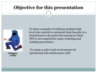
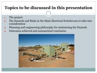
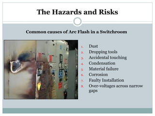
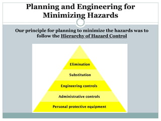
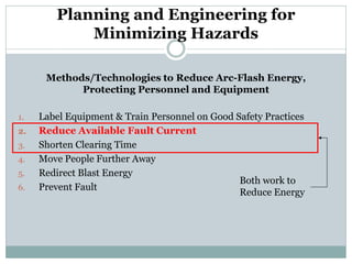
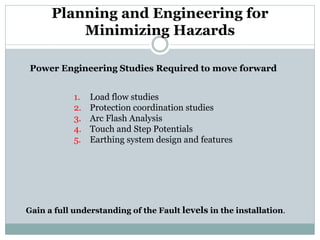
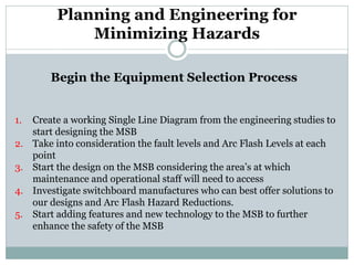

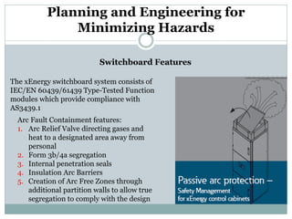
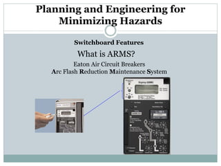
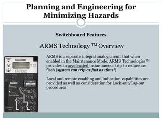

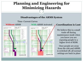
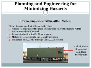
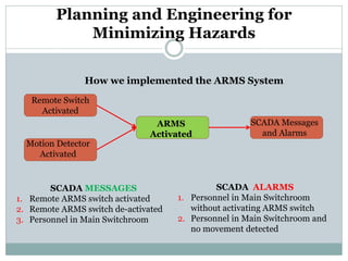
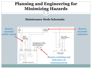
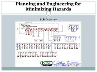
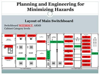
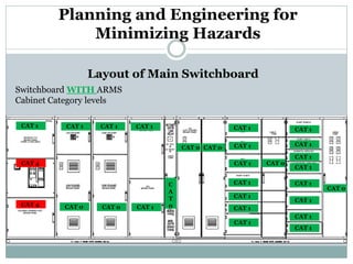
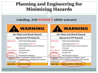
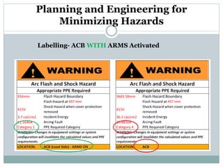
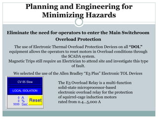


This document discusses methods used to minimize arc flash hazards in an electrical switchroom for a basalt crushing and screening plant. It describes implementing multiple risk controls following the hierarchy of hazard control, including installing an arc flash rated switchboard with features like arc venting, segregation and arc flash reduction technology. The design used studies to reduce fault current and clearing times, and allowed remote operation and monitoring to minimize worker exposure. This combination of engineering and administrative controls successfully lowered hazard categories, reducing required personal protective equipment without compromising coordination.