Download as PDF, PPTX


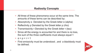


Infrared thermography involves imaging objects through sensing the infrared radiation emitted by their surfaces. William Herschel discovered infrared radiation in 1800. During World War II, infrared technology was used for military applications like detecting soldiers and ships. Heat is a form of energy transferred due to temperature differences, while temperature is a measure of molecular vibration. The three main modes of heat transfer are conduction, convection, and radiation. Infrared cameras detect radiation, which differs from other forms of heat transfer by not requiring a medium. Interpreting thermography requires understanding concepts like emissivity and radiosity, which influence the radiation detected.


