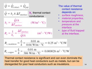
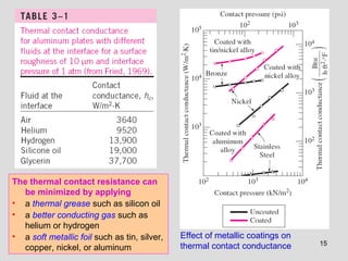
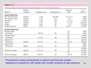
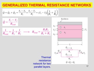
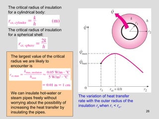
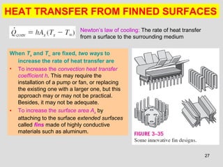
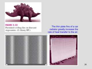
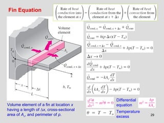
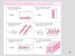
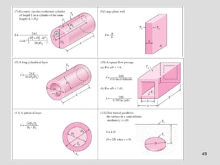
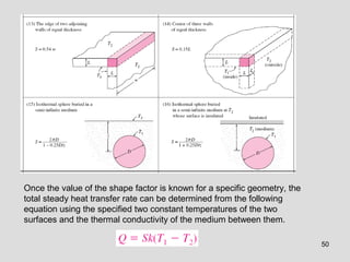
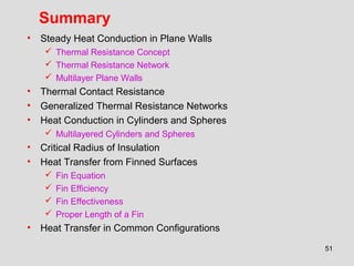
SlideShare a Scribd company logo
1 of 51
Chapter 3
STEADY HEAT CONDUCTION
Copyright © 2011 The McGraw-Hill Companies, Inc. Permission required for reproduction or display.
Heat and Mass Transfer: Fundamentals & Applications
Fourth Edition
Yunus A. Cengel, Afshin J. Ghajar
McGraw-Hill, 2011
PETROLEUM ENGG THERMO
CHE 304
2
Objectives
• Understand the concept of thermal resistance and its
limitations, and develop thermal resistance networks for
practical heat conduction problems
• Solve steady conduction problems that involve multilayer
rectangular, cylindrical, or spherical geometries
• Develop an intuitive understanding of thermal contact
resistance, and circumstances under which it may be
significant
• Identify applications in which insulation may actually
increase heat transfer
• Analyze finned surfaces, and assess how efficiently and
effectively fins enhance heat transfer
• Solve multidimensional practical heat conduction problems
using conduction shape factors
3
STEADY HEAT CONDUCTION IN PLANE WALLS
for steady operation
In steady operation, the rate of heat transfer
through the wall is constant.
Fourier’s law of
heat conduction
Heat transfer through the wall of a house can be
modeled as steady and one-dimensional.
The temperature of the wall in this case depends
on one direction only (say the x-direction) and
can be expressed as T(x).
4
Under steady conditions, the
temperature distribution in a plane
wall is a straight line: dT/dx = const.
The rate of heat conduction through
a plane wall is proportional to the
average thermal conductivity, the
wall area, and the temperature
difference, but is inversely
proportional to the wall thickness.
Once the rate of heat conduction is
available, the temperature T(x) at
any location x can be determined by
replacing T2 by T, and L by x.
5
Analogy between thermal and electrical
resistance concepts.
rate of heat transfer → electric current
thermal resistance → electrical resistance
temperature difference → voltage difference
Thermal Resistance Concept
Conduction resistance of the
wall: Thermal resistance of the
wall against heat conduction.
Thermal resistance of a medium
depends on the geometry and the
thermal properties of the medium.
Electrical resistance
6
Schematic for convection resistance at a surface.
Newton’s law of cooling
Convection resistance of the
surface: Thermal resistance of the
surface against heat convection.
When the convection heat transfer coefficient is very large (h → ∞),
the convection resistance becomes zero and Ts ≈ T.
That is, the surface offers no resistance to convection, and thus it
does not slow down the heat transfer process.
This situation is approached in practice at surfaces where boiling
and condensation occur.
7
Radiation resistance of the
surface: Thermal resistance of the
surface against radiation.
Schematic for
convection and radiation
resistances at a surface.
Radiation heat transfer coefficient
Combined heat transfer
coefficient
8
Thermal Resistance Network
The thermal resistance network for heat transfer through a plane wall subjected to
convection on both sides, and the electrical analogy.
9
U overall heat
transfer coefficient
Once Q is evaluated, the
surface temperature T1 can
be determined from
Temperature drop
The temperature drop across a layer is
proportional to its thermal resistance.
10
The thermal resistance
network for heat transfer
through a two-layer plane
wall subjected to
convection on both sides.
Multilayer
Plane
Walls
11
12
THERMAL CONTACT RESISTANCE
Temperature distribution and heat flow lines along two solid plates
pressed against each other for the case of perfect and imperfect contact.
13
A typical experimental
setup for the
determination of thermal
contact resistance
• When two such surfaces are
pressed against each other, the
peaks form good material
contact but the valleys form
voids filled with air.
• These numerous air gaps of
varying sizes act as insulation
because of the low thermal
conductivity of air.
• Thus, an interface offers some
resistance to heat transfer, and
this resistance per unit interface
area is called the thermal
contact resistance, Rc.
14
hc thermal contact
conductance
The value of thermal
contact resistance
depends on:
• surface roughness,
• material properties,
• temperature and
pressure at the
interface
• type of fluid trapped
at the interface.
Thermal contact resistance is significant and can even dominate the
heat transfer for good heat conductors such as metals, but can be
disregarded for poor heat conductors such as insulations.
15
Effect of metallic coatings on
thermal contact conductance
The thermal contact resistance can
be minimized by applying
• a thermal grease such as silicon oil
• a better conducting gas such as
helium or hydrogen
• a soft metallic foil such as tin, silver,
copper, nickel, or aluminum
16
The thermal contact conductance is highest (and thus the contact
resistance is lowest) for soft metals with smooth surfaces at high pressure.
17
GENERALIZED THERMAL RESISTANCE NETWORKS
Thermal
resistance
network for two
parallel layers.
18
Thermal resistance network for
combined series-parallel
arrangement.
Two assumptions in solving complex
multidimensional heat transfer problems
by treating them as one-dimensional
using the thermal resistance network
are
(1) any plane wall normal to the x-axis is
isothermal (i.e., to assume the
temperature to vary in the x-direction
only)
(2) any plane parallel to the x-axis is
adiabatic (i.e., to assume heat transfer
to occur in the x-direction only)
Do they give the same result?
19
HEAT CONDUCTION IN CYLINDERS AND SPHERES
Heat is lost from a hot-water pipe to
the air outside in the radial
direction, and thus heat transfer
from a long pipe is one-
dimensional.
Heat transfer through the pipe
can be modeled as steady
and one-dimensional.
The temperature of the pipe
depends on one direction only
(the radial r-direction) and can
be expressed as T = T(r).
The temperature is
independent of the azimuthal
angle or the axial distance.
This situation is approximated
in practice in long cylindrical
pipes and spherical
containers.
20
A long cylindrical pipe (or spherical
shell) with specified inner and outer
surface temperatures T1 and T2.
Conduction resistance of the cylinder layer
21
Conduction resistance of the spherical layer
A spherical shell
with specified
inner and outer
surface
temperatures T1
and T2.
22
The thermal resistance
network for a cylindrical (or
spherical) shell subjected
to convection from both the
inner and the outer sides.
for a cylindrical layer
for a spherical layer
23
Multilayered Cylinders and Spheres
The thermal resistance
network for heat transfer
through a three-layered
composite cylinder
subjected to convection
on both sides.
24
Once heat transfer rate Q has been
calculated, the interface temperature
T2 can be determined from any of the
following two relations:
25
CRITICAL RADIUS OF INSULATION
Adding more insulation to a wall or
to the attic always decreases heat
transfer since the heat transfer area
is constant, and adding insulation
always increases the thermal
resistance of the wall without
increasing the convection
resistance.
In a a cylindrical pipe or a spherical
shell, the additional insulation
increases the conduction resistance
of the insulation layer but
decreases the convection
resistance of the surface because
of the increase in the outer surface
area for convection.
The heat transfer from the pipe may
increase or decrease, depending
on which effect dominates.
An insulated cylindrical pipe exposed to
convection from the outer surface and
the thermal resistance network
associated with it.
26
The critical radius of insulation
for a cylindrical body:
The critical radius of insulation
for a spherical shell:
The variation of heat transfer
rate with the outer radius of the
insulation r2 when r1 < rcr.
We can insulate hot-water or
steam pipes freely without
worrying about the possibility of
increasing the heat transfer by
insulating the pipes.
The largest value of the critical
radius we are likely to
encounter is
27
HEAT TRANSFER FROM FINNED SURFACES
When Ts and T∞ are fixed, two ways to
increase the rate of heat transfer are
• To increase the convection heat transfer
coefficient h. This may require the
installation of a pump or fan, or replacing
the existing one with a larger one, but this
approach may or may not be practical.
Besides, it may not be adequate.
• To increase the surface area As by
attaching to the surface extended surfaces
called fins made of highly conductive
materials such as aluminum.
Newton’s law of cooling: The rate of heat transfer
from a surface to the surrounding medium
28
The thin plate fins of a car
radiator greatly increase the
rate of heat transfer to the air.
29
Fin Equation
Volume element of a fin at location x
having a length of ∆x, cross-sectional
area of Ac, and perimeter of p.
Differential
equation
Temperature
excess
30
The general solution of the
differential equation
Boundary condition at fin base
Boundary conditions at the fin
base and the fin tip.
1 Infinitely Long Fin
(Tfin tip = T∞)
Boundary condition at fin tip
The variation of temperature along the fin
The steady rate of heat transfer from the entire fin
31
A long circular fin of uniform
cross section and the variation
of temperature along it.
Under steady conditions, heat
transfer from the exposed surfaces
of the fin is equal to heat conduction
to the fin at the base.
The rate of heat transfer from the fin could also
be determined by considering heat transfer from
a differential volume element of the fin and
integrating it over the entire surface of the fin:
32
2 Negligible Heat Loss from the Fin Tip
(Adiabatic fin tip, Qfin tip = 0)
Boundary condition at fin tip
The variation of temperature along the fin
Heat transfer from the entire fin
Fins are not likely to be so long that their temperature approaches the
surrounding temperature at the tip. A more realistic assumption is for
heat transfer from the fin tip to be negligible since the surface area of
the fin tip is usually a negligible fraction of the total fin area.
33
3 Specified Temperature (Tfin,tip = TL)
In this case the temperature at the end of the fin (the fin tip) is
fixed at a specified temperature TL.
This case could be considered as a generalization of the case of
Infinitely Long Fin where the fin tip temperature was fixed at T∞.
34
4 Convection from Fin Tip
The fin tips, in practice, are exposed to the surroundings, and thus the proper
boundary condition for the fin tip is convection that may also include the effects
of radiation. Consider the case of convection only at the tip. The condition
at the fin tip can be obtained from an energy balance at the fin tip.
35
A practical way of accounting for the
heat loss from the fin tip is to replace
the fin length L in the relation for the
insulated tip case by a corrected
length defined as
Corrected fin length Lc is defined such
that heat transfer from a fin of length Lc
with insulated tip is equal to heat transfer
from the actual fin of length L with
convection at the fin tip.
t the thickness of the rectangular fins
D the diameter of the cylindrical fins
36
Fin Efficiency
37
Zero thermal resistance or infinite
thermal conductivity (Tfin = Tb)
38
Efficiency of straight fins of rectangular, triangular, and parabolic profiles.
39
Efficiency of annular fins of constant thickness t.
40
41
• Fins with triangular and parabolic profiles contain less material
and are more efficient than the ones with rectangular profiles.
• The fin efficiency decreases with increasing fin length. Why?
• How to choose fin length? Increasing the length of the fin beyond
a certain value cannot be justified unless the added benefits
outweigh the added cost.
• Fin lengths that cause the fin efficiency to drop below 60 percent
usually cannot be justified economically.
• The efficiency of most fins used in practice is above 90 percent.
42
Fin
Effectiveness
The
effectivene
ss of a fin
• The thermal conductivity k of the fin
should be as high as possible. Use
aluminum, copper, iron.
• The ratio of the perimeter to the cross-
sectional area of the fin p/Ac should be
as high as possible. Use slender pin fins.
• Low convection heat transfer coefficient
h. Place fins on gas (air) side.
43
Various surface areas associated
with a rectangular surface with
three fins.
Overall effectiveness for a finned surface
The overall fin effectiveness depends
on the fin density (number of fins per
unit length) as well as the
effectiveness of the individual fins.
The overall effectiveness is a better
measure of the performance of a
finned surface than the effectiveness
of the individual fins.
The total rate of heat transfer from a
finned surface
44
Proper Length of a Fin
Because of the gradual temperature drop
along the fin, the region near the fin tip makes
little or no contribution to heat transfer.
mL = 5 → an infinitely long fin
mL = 1 offer a good compromise
between heat transfer
performance and the fin size.
45
A common approximation used in the analysis of fins is to assume the fin
temperature to vary in one direction only (along the fin length) and the
temperature variation along other directions is negligible.
Perhaps you are wondering if this one-dimensional approximation is a
reasonable one.
This is certainly the case for fins made of thin metal sheets such as the fins
on a car radiator, but we wouldn’t be so sure for fins made of thick
materials.
Studies have shown that the error involved in one-dimensional fin analysis
is negligible (less than about 1 percent) when
where δ is the characteristic thickness of the fin, which is taken to
be the plate thickness t for rectangular fins and the diameter D for
cylindrical ones.
46
• Heat sinks: Specially
designed finned surfaces
which are commonly used in
the cooling of electronic
equipment, and involve one-
of-a-kind complex
geometries.
• The heat transfer
performance of heat sinks is
usually expressed in terms of
their thermal resistances R.
• A small value of thermal
resistance indicates a small
temperature drop across the
heat sink, and thus a high fin
efficiency.
47
HEAT TRANSFER IN COMMON CONFIGURATIONS
So far, we have considered heat transfer in simple geometries such as large plane
walls, long cylinders, and spheres.
This is because heat transfer in such geometries can be approximated as one-
dimensional.
But many problems encountered in practice are two- or three-dimensional and
involve rather complicated geometries for which no simple solutions are available.
An important class of heat transfer problems for which simple solutions are
obtained encompasses those involving two surfaces maintained at constant
temperatures T1 and T2.
The steady rate of heat transfer between these two surfaces is expressed as
S: conduction shape factor
k: the thermal conductivity of the medium between the surfaces
The conduction shape factor depends on the geometry of the system only.
Conduction shape factors are applicable only when heat transfer between
the two surfaces is by conduction.
Relationship between the conduction
shape factor and the thermal resistance
48
49
50
Once the value of the shape factor is known for a specific geometry, the
total steady heat transfer rate can be determined from the following
equation using the specified two constant temperatures of the two
surfaces and the thermal conductivity of the medium between them.
51
Summary
• Steady Heat Conduction in Plane Walls
 Thermal Resistance Concept
 Thermal Resistance Network
 Multilayer Plane Walls
• Thermal Contact Resistance
• Generalized Thermal Resistance Networks
• Heat Conduction in Cylinders and Spheres
 Multilayered Cylinders and Spheres
• Critical Radius of Insulation
• Heat Transfer from Finned Surfaces
 Fin Equation
 Fin Efficiency
 Fin Effectiveness
 Proper Length of a Fin
• Heat Transfer in Common Configurations

More Related Content

What's hot

One-dimensional conduction-with_no_heat_generation
One-dimensional conduction-with_no_heat_generationOne-dimensional conduction-with_no_heat_generation
One-dimensional conduction-with_no_heat_generationtmuliya
 
Chapter 5 NUMERICAL METHODS IN HEAT CONDUCTION
Chapter 5NUMERICAL METHODS IN HEAT CONDUCTIONChapter 5NUMERICAL METHODS IN HEAT CONDUCTION
Chapter 5 NUMERICAL METHODS IN HEAT CONDUCTIONAbdul Moiz Dota
 
Boiling & condensation
Boiling & condensationBoiling & condensation
Boiling & condensationziad zohdy
 
SSL4 Steady Heat Conduction
SSL4 Steady Heat ConductionSSL4 Steady Heat Conduction
SSL4 Steady Heat ConductionKeith Vaugh
 
Chapter 1 INTRODUCTION AND BASIC CONCEPTS
Chapter 1INTRODUCTION AND BASIC CONCEPTSChapter 1INTRODUCTION AND BASIC CONCEPTS
Chapter 1 INTRODUCTION AND BASIC CONCEPTSAbdul Moiz Dota
 
heat conduction equations
heat conduction equationsheat conduction equations
heat conduction equationsZahir Baloch
 
Solution Manual – Heat and Mass Transfer: Fundamentals and Application, 5th e...
Solution Manual – Heat and Mass Transfer: Fundamentals and Application, 5th e...Solution Manual – Heat and Mass Transfer: Fundamentals and Application, 5th e...
Solution Manual – Heat and Mass Transfer: Fundamentals and Application, 5th e...kl kl
 
W4_Lecture_Transient heat conduction.ppt
W4_Lecture_Transient heat conduction.pptW4_Lecture_Transient heat conduction.ppt
W4_Lecture_Transient heat conduction.pptMike275736
 
Chapter 1 introduction of heat transfer
Chapter 1 introduction of heat transferChapter 1 introduction of heat transfer
Chapter 1 introduction of heat transferPh Yiu
 
Convection of heat transfer
Convection of heat transferConvection of heat transfer
Convection of heat transferMahammed Janu
 
Transient heat-conduction-Part-I
Transient heat-conduction-Part-ITransient heat-conduction-Part-I
Transient heat-conduction-Part-Itmuliya
 
Lectures on Heat Transfer - Introduction - Applications - Fundamentals - Gove...
Lectures on Heat Transfer - Introduction - Applications - Fundamentals - Gove...Lectures on Heat Transfer - Introduction - Applications - Fundamentals - Gove...
Lectures on Heat Transfer - Introduction - Applications - Fundamentals - Gove...tmuliya
 

What's hot (20)

Heat 4e chap08_lecture
Heat 4e chap08_lectureHeat 4e chap08_lecture
Heat 4e chap08_lecture
 
Heat 4e chap13_lecture
Heat 4e chap13_lectureHeat 4e chap13_lecture
Heat 4e chap13_lecture
 
One-dimensional conduction-with_no_heat_generation
One-dimensional conduction-with_no_heat_generationOne-dimensional conduction-with_no_heat_generation
One-dimensional conduction-with_no_heat_generation
 
Chapter 5 NUMERICAL METHODS IN HEAT CONDUCTION
Chapter 5NUMERICAL METHODS IN HEAT CONDUCTIONChapter 5NUMERICAL METHODS IN HEAT CONDUCTION
Chapter 5 NUMERICAL METHODS IN HEAT CONDUCTION
 
Boiling & condensation
Boiling & condensationBoiling & condensation
Boiling & condensation
 
Heat 4e chap03_lecture
Heat 4e chap03_lectureHeat 4e chap03_lecture
Heat 4e chap03_lecture
 
SSL4 Steady Heat Conduction
SSL4 Steady Heat ConductionSSL4 Steady Heat Conduction
SSL4 Steady Heat Conduction
 
Lec03
Lec03Lec03
Lec03
 
Chapter 4 transient heat condution
Chapter 4 transient heat condution Chapter 4 transient heat condution
Chapter 4 transient heat condution
 
Chapter 1 INTRODUCTION AND BASIC CONCEPTS
Chapter 1INTRODUCTION AND BASIC CONCEPTSChapter 1INTRODUCTION AND BASIC CONCEPTS
Chapter 1 INTRODUCTION AND BASIC CONCEPTS
 
heat conduction equations
heat conduction equationsheat conduction equations
heat conduction equations
 
Solution Manual – Heat and Mass Transfer: Fundamentals and Application, 5th e...
Solution Manual – Heat and Mass Transfer: Fundamentals and Application, 5th e...Solution Manual – Heat and Mass Transfer: Fundamentals and Application, 5th e...
Solution Manual – Heat and Mass Transfer: Fundamentals and Application, 5th e...
 
W4_Lecture_Transient heat conduction.ppt
W4_Lecture_Transient heat conduction.pptW4_Lecture_Transient heat conduction.ppt
W4_Lecture_Transient heat conduction.ppt
 
Power cycles 1
Power cycles 1Power cycles 1
Power cycles 1
 
Throttling calorimeter
Throttling calorimeterThrottling calorimeter
Throttling calorimeter
 
Chapter 1 introduction of heat transfer
Chapter 1 introduction of heat transferChapter 1 introduction of heat transfer
Chapter 1 introduction of heat transfer
 
Heat 4e chap12_lecture
Heat 4e chap12_lectureHeat 4e chap12_lecture
Heat 4e chap12_lecture
 
Convection of heat transfer
Convection of heat transferConvection of heat transfer
Convection of heat transfer
 
Transient heat-conduction-Part-I
Transient heat-conduction-Part-ITransient heat-conduction-Part-I
Transient heat-conduction-Part-I
 
Lectures on Heat Transfer - Introduction - Applications - Fundamentals - Gove...
Lectures on Heat Transfer - Introduction - Applications - Fundamentals - Gove...Lectures on Heat Transfer - Introduction - Applications - Fundamentals - Gove...
Lectures on Heat Transfer - Introduction - Applications - Fundamentals - Gove...
 

Similar to Heat Transfer Through Plane Walls

Ch 2 - Steady state 1-D, Heat conduction.pdf
Ch 2 - Steady state 1-D, Heat conduction.pdfCh 2 - Steady state 1-D, Heat conduction.pdf
Ch 2 - Steady state 1-D, Heat conduction.pdfAyaAya64793
 
Study on Natural Convection in a Square Cavity with Wavy right vertical wall ...
Study on Natural Convection in a Square Cavity with Wavy right vertical wall ...Study on Natural Convection in a Square Cavity with Wavy right vertical wall ...
Study on Natural Convection in a Square Cavity with Wavy right vertical wall ...IOSRJMCE
 
Natural Convection from Heated Rough Surface at the Bottom of Vented Rectangu...
Natural Convection from Heated Rough Surface at the Bottom of Vented Rectangu...Natural Convection from Heated Rough Surface at the Bottom of Vented Rectangu...
Natural Convection from Heated Rough Surface at the Bottom of Vented Rectangu...theijes
 
GATE Mechanical Engineering notes on Heat Transfer
GATE Mechanical Engineering notes on Heat TransferGATE Mechanical Engineering notes on Heat Transfer
GATE Mechanical Engineering notes on Heat TransferHimanshu Vasistha
 
CHAPTER -ONE.pdf
CHAPTER -ONE.pdfCHAPTER -ONE.pdf
CHAPTER -ONE.pdfkoxabey137
 
lecture-1-mechanismsof HT_524.ppt
lecture-1-mechanismsof HT_524.pptlecture-1-mechanismsof HT_524.ppt
lecture-1-mechanismsof HT_524.pptShoebAhmedSyed2
 
HEAT TRANSFER THROUGH PLANE WALL.pptx
HEAT TRANSFER THROUGH PLANE WALL.pptxHEAT TRANSFER THROUGH PLANE WALL.pptx
HEAT TRANSFER THROUGH PLANE WALL.pptxMaheshSahu66
 
Heat Conduction with thermal heat generation.pptx
Heat Conduction with thermal heat generation.pptxHeat Conduction with thermal heat generation.pptx
Heat Conduction with thermal heat generation.pptxBektu Dida
 
2151909 heat transfer e-note (thefreestudy.com) (1)
2151909   heat transfer e-note (thefreestudy.com) (1)2151909   heat transfer e-note (thefreestudy.com) (1)
2151909 heat transfer e-note (thefreestudy.com) (1)varun Raolji
 

Similar to Heat Transfer Through Plane Walls (20)

HMT
HMTHMT
HMT
 
2 marks heat and mass transfer
2 marks   heat and mass transfer2 marks   heat and mass transfer
2 marks heat and mass transfer
 
Lecture 1
Lecture 1Lecture 1
Lecture 1
 
Ch 2 - Steady state 1-D, Heat conduction.pdf
Ch 2 - Steady state 1-D, Heat conduction.pdfCh 2 - Steady state 1-D, Heat conduction.pdf
Ch 2 - Steady state 1-D, Heat conduction.pdf
 
Lecture 2
Lecture 2Lecture 2
Lecture 2
 
Heat_All.pdf
Heat_All.pdfHeat_All.pdf
Heat_All.pdf
 
Study on Natural Convection in a Square Cavity with Wavy right vertical wall ...
Study on Natural Convection in a Square Cavity with Wavy right vertical wall ...Study on Natural Convection in a Square Cavity with Wavy right vertical wall ...
Study on Natural Convection in a Square Cavity with Wavy right vertical wall ...
 
Natural Convection from Heated Rough Surface at the Bottom of Vented Rectangu...
Natural Convection from Heated Rough Surface at the Bottom of Vented Rectangu...Natural Convection from Heated Rough Surface at the Bottom of Vented Rectangu...
Natural Convection from Heated Rough Surface at the Bottom of Vented Rectangu...
 
Module 2.pptx
Module 2.pptxModule 2.pptx
Module 2.pptx
 
GATE Mechanical Engineering notes on Heat Transfer
GATE Mechanical Engineering notes on Heat TransferGATE Mechanical Engineering notes on Heat Transfer
GATE Mechanical Engineering notes on Heat Transfer
 
CHAPTER -ONE.pdf
CHAPTER -ONE.pdfCHAPTER -ONE.pdf
CHAPTER -ONE.pdf
 
basics of HMT
basics of HMTbasics of HMT
basics of HMT
 
lecture-1-mechanismsof HT_524.ppt
lecture-1-mechanismsof HT_524.pptlecture-1-mechanismsof HT_524.ppt
lecture-1-mechanismsof HT_524.ppt
 
HEAT TRANSFER THROUGH PLANE WALL.pptx
HEAT TRANSFER THROUGH PLANE WALL.pptxHEAT TRANSFER THROUGH PLANE WALL.pptx
HEAT TRANSFER THROUGH PLANE WALL.pptx
 
App.Phy_1.pptx
App.Phy_1.pptxApp.Phy_1.pptx
App.Phy_1.pptx
 
Heat Transfer.pdf
Heat Transfer.pdfHeat Transfer.pdf
Heat Transfer.pdf
 
Heat Conduction with thermal heat generation.pptx
Heat Conduction with thermal heat generation.pptxHeat Conduction with thermal heat generation.pptx
Heat Conduction with thermal heat generation.pptx
 
Lecture 18
Lecture 18Lecture 18
Lecture 18
 
Lecture 18
Lecture 18Lecture 18
Lecture 18
 
2151909 heat transfer e-note (thefreestudy.com) (1)
2151909   heat transfer e-note (thefreestudy.com) (1)2151909   heat transfer e-note (thefreestudy.com) (1)
2151909 heat transfer e-note (thefreestudy.com) (1)
 

Recently uploaded

CARE OF CHILD IN INCUBATOR..........pptx
CARE OF CHILD IN INCUBATOR..........pptxCARE OF CHILD IN INCUBATOR..........pptx
CARE OF CHILD IN INCUBATOR..........pptxGaneshChakor2
 
mini mental status format.docx
mini    mental       status     format.docxmini    mental       status     format.docx
mini mental status format.docxPoojaSen20
 
Separation of Lanthanides/ Lanthanides and Actinides
Separation of Lanthanides/ Lanthanides and ActinidesSeparation of Lanthanides/ Lanthanides and Actinides
Separation of Lanthanides/ Lanthanides and ActinidesFatimaKhan178732
 
The basics of sentences session 2pptx copy.pptx
The basics of sentences session 2pptx copy.pptxThe basics of sentences session 2pptx copy.pptx
The basics of sentences session 2pptx copy.pptxheathfieldcps1
 
Paris 2024 Olympic Geographies - an activity
Paris 2024 Olympic Geographies - an activityParis 2024 Olympic Geographies - an activity
Paris 2024 Olympic Geographies - an activityGeoBlogs
 
Contemporary philippine arts from the regions_PPT_Module_12 [Autosaved] (1).pptx
Contemporary philippine arts from the regions_PPT_Module_12 [Autosaved] (1).pptxContemporary philippine arts from the regions_PPT_Module_12 [Autosaved] (1).pptx
Contemporary philippine arts from the regions_PPT_Module_12 [Autosaved] (1).pptxRoyAbrique
 
call girls in Kamla Market (DELHI) 🔝 >༒9953330565🔝 genuine Escort Service 🔝✔️✔️
call girls in Kamla Market (DELHI) 🔝 >༒9953330565🔝 genuine Escort Service 🔝✔️✔️call girls in Kamla Market (DELHI) 🔝 >༒9953330565🔝 genuine Escort Service 🔝✔️✔️
call girls in Kamla Market (DELHI) 🔝 >༒9953330565🔝 genuine Escort Service 🔝✔️✔️9953056974 Low Rate Call Girls In Saket, Delhi NCR
 
Accessible design: Minimum effort, maximum impact
Accessible design: Minimum effort, maximum impactAccessible design: Minimum effort, maximum impact
Accessible design: Minimum effort, maximum impactdawncurless
 
Incoming and Outgoing Shipments in 1 STEP Using Odoo 17
Incoming and Outgoing Shipments in 1 STEP Using Odoo 17Incoming and Outgoing Shipments in 1 STEP Using Odoo 17
Incoming and Outgoing Shipments in 1 STEP Using Odoo 17Celine George
 
Hybridoma Technology ( Production , Purification , and Application )
Hybridoma Technology  ( Production , Purification , and Application  ) Hybridoma Technology  ( Production , Purification , and Application  )
Hybridoma Technology ( Production , Purification , and Application ) Sakshi Ghasle
 
ECONOMIC CONTEXT - LONG FORM TV DRAMA - PPT
ECONOMIC CONTEXT - LONG FORM TV DRAMA - PPTECONOMIC CONTEXT - LONG FORM TV DRAMA - PPT
ECONOMIC CONTEXT - LONG FORM TV DRAMA - PPTiammrhaywood
 
_Math 4-Q4 Week 5.pptx Steps in Collecting Data
_Math 4-Q4 Week 5.pptx Steps in Collecting Data_Math 4-Q4 Week 5.pptx Steps in Collecting Data
_Math 4-Q4 Week 5.pptx Steps in Collecting DataJhengPantaleon
 
A Critique of the Proposed National Education Policy Reform
A Critique of the Proposed National Education Policy ReformA Critique of the Proposed National Education Policy Reform
A Critique of the Proposed National Education Policy ReformChameera Dedduwage
 
“Oh GOSH! Reflecting on Hackteria's Collaborative Practices in a Global Do-It...
“Oh GOSH! Reflecting on Hackteria's Collaborative Practices in a Global Do-It...“Oh GOSH! Reflecting on Hackteria's Collaborative Practices in a Global Do-It...
“Oh GOSH! Reflecting on Hackteria's Collaborative Practices in a Global Do-It...Marc Dusseiller Dusjagr
 
Science 7 - LAND and SEA BREEZE and its Characteristics
Science 7 - LAND and SEA BREEZE and its CharacteristicsScience 7 - LAND and SEA BREEZE and its Characteristics
Science 7 - LAND and SEA BREEZE and its CharacteristicsKarinaGenton
 

Recently uploaded (20)

CARE OF CHILD IN INCUBATOR..........pptx
CARE OF CHILD IN INCUBATOR..........pptxCARE OF CHILD IN INCUBATOR..........pptx
CARE OF CHILD IN INCUBATOR..........pptx
 
Staff of Color (SOC) Retention Efforts DDSD
Staff of Color (SOC) Retention Efforts DDSDStaff of Color (SOC) Retention Efforts DDSD
Staff of Color (SOC) Retention Efforts DDSD
 
mini mental status format.docx
mini    mental       status     format.docxmini    mental       status     format.docx
mini mental status format.docx
 
Separation of Lanthanides/ Lanthanides and Actinides
Separation of Lanthanides/ Lanthanides and ActinidesSeparation of Lanthanides/ Lanthanides and Actinides
Separation of Lanthanides/ Lanthanides and Actinides
 
The basics of sentences session 2pptx copy.pptx
The basics of sentences session 2pptx copy.pptxThe basics of sentences session 2pptx copy.pptx
The basics of sentences session 2pptx copy.pptx
 
Paris 2024 Olympic Geographies - an activity
Paris 2024 Olympic Geographies - an activityParis 2024 Olympic Geographies - an activity
Paris 2024 Olympic Geographies - an activity
 
Contemporary philippine arts from the regions_PPT_Module_12 [Autosaved] (1).pptx
Contemporary philippine arts from the regions_PPT_Module_12 [Autosaved] (1).pptxContemporary philippine arts from the regions_PPT_Module_12 [Autosaved] (1).pptx
Contemporary philippine arts from the regions_PPT_Module_12 [Autosaved] (1).pptx
 
call girls in Kamla Market (DELHI) 🔝 >༒9953330565🔝 genuine Escort Service 🔝✔️✔️
call girls in Kamla Market (DELHI) 🔝 >༒9953330565🔝 genuine Escort Service 🔝✔️✔️call girls in Kamla Market (DELHI) 🔝 >༒9953330565🔝 genuine Escort Service 🔝✔️✔️
call girls in Kamla Market (DELHI) 🔝 >༒9953330565🔝 genuine Escort Service 🔝✔️✔️
 
Accessible design: Minimum effort, maximum impact
Accessible design: Minimum effort, maximum impactAccessible design: Minimum effort, maximum impact
Accessible design: Minimum effort, maximum impact
 
Incoming and Outgoing Shipments in 1 STEP Using Odoo 17
Incoming and Outgoing Shipments in 1 STEP Using Odoo 17Incoming and Outgoing Shipments in 1 STEP Using Odoo 17
Incoming and Outgoing Shipments in 1 STEP Using Odoo 17
 
Model Call Girl in Bikash Puri Delhi reach out to us at 🔝9953056974🔝
Model Call Girl in Bikash Puri  Delhi reach out to us at 🔝9953056974🔝Model Call Girl in Bikash Puri  Delhi reach out to us at 🔝9953056974🔝
Model Call Girl in Bikash Puri Delhi reach out to us at 🔝9953056974🔝
 
9953330565 Low Rate Call Girls In Rohini Delhi NCR
9953330565 Low Rate Call Girls In Rohini  Delhi NCR9953330565 Low Rate Call Girls In Rohini  Delhi NCR
9953330565 Low Rate Call Girls In Rohini Delhi NCR
 
Código Creativo y Arte de Software | Unidad 1
Código Creativo y Arte de Software | Unidad 1Código Creativo y Arte de Software | Unidad 1
Código Creativo y Arte de Software | Unidad 1
 
TataKelola dan KamSiber Kecerdasan Buatan v022.pdf
TataKelola dan KamSiber Kecerdasan Buatan v022.pdfTataKelola dan KamSiber Kecerdasan Buatan v022.pdf
TataKelola dan KamSiber Kecerdasan Buatan v022.pdf
 
Hybridoma Technology ( Production , Purification , and Application )
Hybridoma Technology  ( Production , Purification , and Application  ) Hybridoma Technology  ( Production , Purification , and Application  )
Hybridoma Technology ( Production , Purification , and Application )
 
ECONOMIC CONTEXT - LONG FORM TV DRAMA - PPT
ECONOMIC CONTEXT - LONG FORM TV DRAMA - PPTECONOMIC CONTEXT - LONG FORM TV DRAMA - PPT
ECONOMIC CONTEXT - LONG FORM TV DRAMA - PPT
 
_Math 4-Q4 Week 5.pptx Steps in Collecting Data
_Math 4-Q4 Week 5.pptx Steps in Collecting Data_Math 4-Q4 Week 5.pptx Steps in Collecting Data
_Math 4-Q4 Week 5.pptx Steps in Collecting Data
 
A Critique of the Proposed National Education Policy Reform
A Critique of the Proposed National Education Policy ReformA Critique of the Proposed National Education Policy Reform
A Critique of the Proposed National Education Policy Reform
 
“Oh GOSH! Reflecting on Hackteria's Collaborative Practices in a Global Do-It...
“Oh GOSH! Reflecting on Hackteria's Collaborative Practices in a Global Do-It...“Oh GOSH! Reflecting on Hackteria's Collaborative Practices in a Global Do-It...
“Oh GOSH! Reflecting on Hackteria's Collaborative Practices in a Global Do-It...
 
Science 7 - LAND and SEA BREEZE and its Characteristics
Science 7 - LAND and SEA BREEZE and its CharacteristicsScience 7 - LAND and SEA BREEZE and its Characteristics
Science 7 - LAND and SEA BREEZE and its Characteristics
 

Heat Transfer Through Plane Walls

  • 1. Chapter 3 STEADY HEAT CONDUCTION Copyright © 2011 The McGraw-Hill Companies, Inc. Permission required for reproduction or display. Heat and Mass Transfer: Fundamentals & Applications Fourth Edition Yunus A. Cengel, Afshin J. Ghajar McGraw-Hill, 2011 PETROLEUM ENGG THERMO CHE 304
  • 2. 2 Objectives • Understand the concept of thermal resistance and its limitations, and develop thermal resistance networks for practical heat conduction problems • Solve steady conduction problems that involve multilayer rectangular, cylindrical, or spherical geometries • Develop an intuitive understanding of thermal contact resistance, and circumstances under which it may be significant • Identify applications in which insulation may actually increase heat transfer • Analyze finned surfaces, and assess how efficiently and effectively fins enhance heat transfer • Solve multidimensional practical heat conduction problems using conduction shape factors
  • 3. 3 STEADY HEAT CONDUCTION IN PLANE WALLS for steady operation In steady operation, the rate of heat transfer through the wall is constant. Fourier’s law of heat conduction Heat transfer through the wall of a house can be modeled as steady and one-dimensional. The temperature of the wall in this case depends on one direction only (say the x-direction) and can be expressed as T(x).
  • 4. 4 Under steady conditions, the temperature distribution in a plane wall is a straight line: dT/dx = const. The rate of heat conduction through a plane wall is proportional to the average thermal conductivity, the wall area, and the temperature difference, but is inversely proportional to the wall thickness. Once the rate of heat conduction is available, the temperature T(x) at any location x can be determined by replacing T2 by T, and L by x.
  • 5. 5 Analogy between thermal and electrical resistance concepts. rate of heat transfer → electric current thermal resistance → electrical resistance temperature difference → voltage difference Thermal Resistance Concept Conduction resistance of the wall: Thermal resistance of the wall against heat conduction. Thermal resistance of a medium depends on the geometry and the thermal properties of the medium. Electrical resistance
  • 6. 6 Schematic for convection resistance at a surface. Newton’s law of cooling Convection resistance of the surface: Thermal resistance of the surface against heat convection. When the convection heat transfer coefficient is very large (h → ∞), the convection resistance becomes zero and Ts ≈ T. That is, the surface offers no resistance to convection, and thus it does not slow down the heat transfer process. This situation is approached in practice at surfaces where boiling and condensation occur.
  • 7. 7 Radiation resistance of the surface: Thermal resistance of the surface against radiation. Schematic for convection and radiation resistances at a surface. Radiation heat transfer coefficient Combined heat transfer coefficient
  • 8. 8 Thermal Resistance Network The thermal resistance network for heat transfer through a plane wall subjected to convection on both sides, and the electrical analogy.
  • 9. 9 U overall heat transfer coefficient Once Q is evaluated, the surface temperature T1 can be determined from Temperature drop The temperature drop across a layer is proportional to its thermal resistance.
  • 10. 10 The thermal resistance network for heat transfer through a two-layer plane wall subjected to convection on both sides. Multilayer Plane Walls
  • 11. 11
  • 12. 12 THERMAL CONTACT RESISTANCE Temperature distribution and heat flow lines along two solid plates pressed against each other for the case of perfect and imperfect contact.
  • 13. 13 A typical experimental setup for the determination of thermal contact resistance • When two such surfaces are pressed against each other, the peaks form good material contact but the valleys form voids filled with air. • These numerous air gaps of varying sizes act as insulation because of the low thermal conductivity of air. • Thus, an interface offers some resistance to heat transfer, and this resistance per unit interface area is called the thermal contact resistance, Rc.
  • 14. 14 hc thermal contact conductance The value of thermal contact resistance depends on: • surface roughness, • material properties, • temperature and pressure at the interface • type of fluid trapped at the interface. Thermal contact resistance is significant and can even dominate the heat transfer for good heat conductors such as metals, but can be disregarded for poor heat conductors such as insulations.
  • 15. 15 Effect of metallic coatings on thermal contact conductance The thermal contact resistance can be minimized by applying • a thermal grease such as silicon oil • a better conducting gas such as helium or hydrogen • a soft metallic foil such as tin, silver, copper, nickel, or aluminum
  • 16. 16 The thermal contact conductance is highest (and thus the contact resistance is lowest) for soft metals with smooth surfaces at high pressure.
  • 17. 17 GENERALIZED THERMAL RESISTANCE NETWORKS Thermal resistance network for two parallel layers.
  • 18. 18 Thermal resistance network for combined series-parallel arrangement. Two assumptions in solving complex multidimensional heat transfer problems by treating them as one-dimensional using the thermal resistance network are (1) any plane wall normal to the x-axis is isothermal (i.e., to assume the temperature to vary in the x-direction only) (2) any plane parallel to the x-axis is adiabatic (i.e., to assume heat transfer to occur in the x-direction only) Do they give the same result?
  • 19. 19 HEAT CONDUCTION IN CYLINDERS AND SPHERES Heat is lost from a hot-water pipe to the air outside in the radial direction, and thus heat transfer from a long pipe is one- dimensional. Heat transfer through the pipe can be modeled as steady and one-dimensional. The temperature of the pipe depends on one direction only (the radial r-direction) and can be expressed as T = T(r). The temperature is independent of the azimuthal angle or the axial distance. This situation is approximated in practice in long cylindrical pipes and spherical containers.
  • 20. 20 A long cylindrical pipe (or spherical shell) with specified inner and outer surface temperatures T1 and T2. Conduction resistance of the cylinder layer
  • 21. 21 Conduction resistance of the spherical layer A spherical shell with specified inner and outer surface temperatures T1 and T2.
  • 22. 22 The thermal resistance network for a cylindrical (or spherical) shell subjected to convection from both the inner and the outer sides. for a cylindrical layer for a spherical layer
  • 23. 23 Multilayered Cylinders and Spheres The thermal resistance network for heat transfer through a three-layered composite cylinder subjected to convection on both sides.
  • 24. 24 Once heat transfer rate Q has been calculated, the interface temperature T2 can be determined from any of the following two relations:
  • 25. 25 CRITICAL RADIUS OF INSULATION Adding more insulation to a wall or to the attic always decreases heat transfer since the heat transfer area is constant, and adding insulation always increases the thermal resistance of the wall without increasing the convection resistance. In a a cylindrical pipe or a spherical shell, the additional insulation increases the conduction resistance of the insulation layer but decreases the convection resistance of the surface because of the increase in the outer surface area for convection. The heat transfer from the pipe may increase or decrease, depending on which effect dominates. An insulated cylindrical pipe exposed to convection from the outer surface and the thermal resistance network associated with it.
  • 26. 26 The critical radius of insulation for a cylindrical body: The critical radius of insulation for a spherical shell: The variation of heat transfer rate with the outer radius of the insulation r2 when r1 < rcr. We can insulate hot-water or steam pipes freely without worrying about the possibility of increasing the heat transfer by insulating the pipes. The largest value of the critical radius we are likely to encounter is
  • 27. 27 HEAT TRANSFER FROM FINNED SURFACES When Ts and T∞ are fixed, two ways to increase the rate of heat transfer are • To increase the convection heat transfer coefficient h. This may require the installation of a pump or fan, or replacing the existing one with a larger one, but this approach may or may not be practical. Besides, it may not be adequate. • To increase the surface area As by attaching to the surface extended surfaces called fins made of highly conductive materials such as aluminum. Newton’s law of cooling: The rate of heat transfer from a surface to the surrounding medium
  • 28. 28 The thin plate fins of a car radiator greatly increase the rate of heat transfer to the air.
  • 29. 29 Fin Equation Volume element of a fin at location x having a length of ∆x, cross-sectional area of Ac, and perimeter of p. Differential equation Temperature excess
  • 30. 30 The general solution of the differential equation Boundary condition at fin base Boundary conditions at the fin base and the fin tip. 1 Infinitely Long Fin (Tfin tip = T∞) Boundary condition at fin tip The variation of temperature along the fin The steady rate of heat transfer from the entire fin
  • 31. 31 A long circular fin of uniform cross section and the variation of temperature along it. Under steady conditions, heat transfer from the exposed surfaces of the fin is equal to heat conduction to the fin at the base. The rate of heat transfer from the fin could also be determined by considering heat transfer from a differential volume element of the fin and integrating it over the entire surface of the fin:
  • 32. 32 2 Negligible Heat Loss from the Fin Tip (Adiabatic fin tip, Qfin tip = 0) Boundary condition at fin tip The variation of temperature along the fin Heat transfer from the entire fin Fins are not likely to be so long that their temperature approaches the surrounding temperature at the tip. A more realistic assumption is for heat transfer from the fin tip to be negligible since the surface area of the fin tip is usually a negligible fraction of the total fin area.
  • 33. 33 3 Specified Temperature (Tfin,tip = TL) In this case the temperature at the end of the fin (the fin tip) is fixed at a specified temperature TL. This case could be considered as a generalization of the case of Infinitely Long Fin where the fin tip temperature was fixed at T∞.
  • 34. 34 4 Convection from Fin Tip The fin tips, in practice, are exposed to the surroundings, and thus the proper boundary condition for the fin tip is convection that may also include the effects of radiation. Consider the case of convection only at the tip. The condition at the fin tip can be obtained from an energy balance at the fin tip.
  • 35. 35 A practical way of accounting for the heat loss from the fin tip is to replace the fin length L in the relation for the insulated tip case by a corrected length defined as Corrected fin length Lc is defined such that heat transfer from a fin of length Lc with insulated tip is equal to heat transfer from the actual fin of length L with convection at the fin tip. t the thickness of the rectangular fins D the diameter of the cylindrical fins
  • 37. 37 Zero thermal resistance or infinite thermal conductivity (Tfin = Tb)
  • 38. 38 Efficiency of straight fins of rectangular, triangular, and parabolic profiles.
  • 39. 39 Efficiency of annular fins of constant thickness t.
  • 40. 40
  • 41. 41 • Fins with triangular and parabolic profiles contain less material and are more efficient than the ones with rectangular profiles. • The fin efficiency decreases with increasing fin length. Why? • How to choose fin length? Increasing the length of the fin beyond a certain value cannot be justified unless the added benefits outweigh the added cost. • Fin lengths that cause the fin efficiency to drop below 60 percent usually cannot be justified economically. • The efficiency of most fins used in practice is above 90 percent.
  • 42. 42 Fin Effectiveness The effectivene ss of a fin • The thermal conductivity k of the fin should be as high as possible. Use aluminum, copper, iron. • The ratio of the perimeter to the cross- sectional area of the fin p/Ac should be as high as possible. Use slender pin fins. • Low convection heat transfer coefficient h. Place fins on gas (air) side.
  • 43. 43 Various surface areas associated with a rectangular surface with three fins. Overall effectiveness for a finned surface The overall fin effectiveness depends on the fin density (number of fins per unit length) as well as the effectiveness of the individual fins. The overall effectiveness is a better measure of the performance of a finned surface than the effectiveness of the individual fins. The total rate of heat transfer from a finned surface
  • 44. 44 Proper Length of a Fin Because of the gradual temperature drop along the fin, the region near the fin tip makes little or no contribution to heat transfer. mL = 5 → an infinitely long fin mL = 1 offer a good compromise between heat transfer performance and the fin size.
  • 45. 45 A common approximation used in the analysis of fins is to assume the fin temperature to vary in one direction only (along the fin length) and the temperature variation along other directions is negligible. Perhaps you are wondering if this one-dimensional approximation is a reasonable one. This is certainly the case for fins made of thin metal sheets such as the fins on a car radiator, but we wouldn’t be so sure for fins made of thick materials. Studies have shown that the error involved in one-dimensional fin analysis is negligible (less than about 1 percent) when where δ is the characteristic thickness of the fin, which is taken to be the plate thickness t for rectangular fins and the diameter D for cylindrical ones.
  • 46. 46 • Heat sinks: Specially designed finned surfaces which are commonly used in the cooling of electronic equipment, and involve one- of-a-kind complex geometries. • The heat transfer performance of heat sinks is usually expressed in terms of their thermal resistances R. • A small value of thermal resistance indicates a small temperature drop across the heat sink, and thus a high fin efficiency.
  • 47. 47 HEAT TRANSFER IN COMMON CONFIGURATIONS So far, we have considered heat transfer in simple geometries such as large plane walls, long cylinders, and spheres. This is because heat transfer in such geometries can be approximated as one- dimensional. But many problems encountered in practice are two- or three-dimensional and involve rather complicated geometries for which no simple solutions are available. An important class of heat transfer problems for which simple solutions are obtained encompasses those involving two surfaces maintained at constant temperatures T1 and T2. The steady rate of heat transfer between these two surfaces is expressed as S: conduction shape factor k: the thermal conductivity of the medium between the surfaces The conduction shape factor depends on the geometry of the system only. Conduction shape factors are applicable only when heat transfer between the two surfaces is by conduction. Relationship between the conduction shape factor and the thermal resistance
  • 48. 48
  • 49. 49
  • 50. 50 Once the value of the shape factor is known for a specific geometry, the total steady heat transfer rate can be determined from the following equation using the specified two constant temperatures of the two surfaces and the thermal conductivity of the medium between them.
  • 51. 51 Summary • Steady Heat Conduction in Plane Walls  Thermal Resistance Concept  Thermal Resistance Network  Multilayer Plane Walls • Thermal Contact Resistance • Generalized Thermal Resistance Networks • Heat Conduction in Cylinders and Spheres  Multilayered Cylinders and Spheres • Critical Radius of Insulation • Heat Transfer from Finned Surfaces  Fin Equation  Fin Efficiency  Fin Effectiveness  Proper Length of a Fin • Heat Transfer in Common Configurations