This document is an edited collection of papers on carbon nanotubes. It contains an editorial and preface introducing the topic of carbon nanotubes. The collection includes papers on the production, structure, properties, and applications of carbon nanotubes. The papers cover topics such as the synthesis of carbon nanotubes from vapor-grown carbon fibers, the growth mechanisms of nanotubes, purification methods, theoretical descriptions of nanotube structure and properties, experimental studies of electronic and vibrational properties, and potential applications of carbon nanotubes.


![PREFACE
Since the start of this decade (the 1990's), fullerene efficiency and smaller nanotubes are discussed in
research has blossomed in many different directions, the article by Ivanov and coworkers. The quantum
and has attracted a great deal of attention to Carbon aspects of carbon nanotubes, stemming from their
Science. It was therefore natural to assemble, under small diameters, which contain only a small number
the guest editorship of Professor Harry Kroto, one of carbon atoms (< lo2), lead to remarkable sym-
of the earliest books on the subject of fullerenes 111, metries and electronic structure, as described in the
a book that has had a significant impact on the articles by Dresselhaus, Dresselhaus and Saito and
subsequent developments of the fullerene field. by Mintmire and White. Because of the simplicity
Stemming from the success of the first volume, it is of the single-wall nanotube, theoretical work has
now appropriate to assemble a follow-on volume on focussed almost exclusively on single-wall nanotubes.
Carbon Nanotubes. It is furthermore fitting that The remarkable electronic properties predicted for
Dr Sumio Iijima and Professor Morinobu Endo serve carbon nanotubes are their ability to be either con-
as the Guest Editors of this volume, because they are ducting or to have semiconductor behavior, depending
the researchers who are most responsible for opening on purely geometrical factors, namely the diameter
up the field of carbon nanotubes. Though the field and chirality of the nanotubes. The existence of
is still young and rapidly developing, this is a very conducting nanotubes thus relates directly to the
appropriate time to publish a book on the very active symmetry-imposed band degeneracy and zero-gap
topic of carbon nanotubes. semiconductor behavior for electrons in a two-dirnen-
The goal of this book is thus to assess progress in sional single layer of graphite (called a graphene
the field, to identify fruitful new research directions, sheet). The existence of finite gap semiconducting
to summarize the substantial progress that has thus behavior arises from quantum effects connected with
far been made with theoretical studies, and to clarify the small number of wavevectors associated with
some unusual features of carbon-based materials that the circumferential direction of the nanotubes. The
are relevant to the interpretation of experiments on article by Kiang et al. reviews the present status of the
carbon nanotubes that are now being so actively synthesis of single-wall nanotubes and the theoretical
pursued. A second goal of this book is thus to implications of these single-wall nanotubes. The geo-
stimulate further progress in research on carbon metrical considerations governing the closure, helicity
nanotubes and related materials. and interlayer distance of successive layers in multi-
'The birth of the field of carbon nanotubes is layer carbon nanotubes are discussed in the paper by
marked by the publication by Iijima of the observation Setton.
of multi-walled nanotubes with outer diameters as Study of the structure of carbon nanotubes and
small as 55 A, and inner diameters as small as 23 A, their common defects is well summarized in the
and a nanotube consisting of only two coaxial review by Sattler, who was able to obtain scanning
cyknders [2]. This paper was important in making tunneling microscopy (STM) images of carbon nan-
the connection between carbon fullerenes, which are otube surfaces with atomic resolution. A discussion
quantum dots, with carbon nanotubes, which are of common defects found in carbon nanotubes,
quantum wires. Furthermore this seminal paper [2] including topological, rehybridization and bonding
has stimulated extensive theoretical and experimental defects is presented by Ebbesen and Takada. The
research for the past five years and has led to the review by Ihara and Itoh of the many helical and
creation of a rapidly developing research field. toroidal forms of carbon nanostructures that may be
The direct linking of carbon nanotubes to graphite realized provides insight into the potential breadth
and the continuity in synthesis, structure and proper- of this field. The joining of two dissimilar nanotubes
ties between carbon nanotubes and vapor grown is considered in the article by Fonseca et al., where
carbon fibers is reviewed by the present leaders of this these concepts are also applied to more complex
area, Professor M. Endo, H. Kroto, and co-workers. structures such as tori and coiled nanotubes. The role
Further insight into the growth mechanism is pre- of semi-toroidal networks in linking the inner and
sented in the article by Colbert and Smalley. New outer walls of a double-walled carbon nanotube is
synthesis methods leading to enhanced production discussed in the paper by Sarkar et al.
ix](https://image.slidesharecdn.com/13709313-carbon-nanotubes-120928071547-phpapp01/85/13709313-carbon-nanotubes-12-320.jpg)
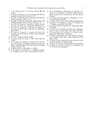
![PYROLYTIC CARBON NANOTUBES FROM VAPOR-GROWN
CARBON FIBERS
ENDO,'Kmn TAKEUCHI,'
MORINOBU KIYOHARU KOBORI,'KATSUSHI
TAKAHASHI,
I
HAROLD K R O T O ,and A. SARKAR'
W. ~
'Faculty of Engineering, Shinshu University, 500 Wakasato, Nagano 380, Japan
'School of Chemistry and Molecular Sciences, University of Sussex, Brighton BNl SQJ, U.K.
(Received 21 November 1994; accepted 10 February 1995)
Abstract-The structure of as-grown and heat-treated pyrolytic carbon nanotubes (PCNTs) produced by
hydrocarbon pyrolysis are discussed on the basis of a possible growth process. The structures are com-
pared with those of nanotubes obtained by the arc method (ACNT, arc-formed carbon nanotubes). PCNTs,
with and without secondary pyrolytic deposition (which results in diameter increase) are found to form
during pyrolysis of benzene at temperatures ca. 1060°C under hydrogen. PCNTs after heat treatment at
above 2800°C under argon exhibit have improved stability and can be studied by high-resolution trans-
mission electron microscopy (HRTEM). The microstructures of PCNTs closely resemble those of vapor-
grown carbon fibers (VGCFs). Some VGCFs that have micro-sized diameters appear to have nanotube
inner cross-sections that have different mechanical properties from those of the outer pyrolytic sections.
PCNTs initially appear to grow as ultra-thin graphene tubes with central hollow cores (diameter ca. 2 nm
or more) and catalytic particles are not observed at the tip of these tubes. The secondary pyrolytic depo-
sition, which results in characteristic thickening by addition of extra cylindrical carbon layers, appears to
occur simultaneously with nanotube lengthening growth. After heat treatment, HRTEM studies indicate
clearly that the hollow cores are closed at the ends of polygonized hemi-spherical carbon caps. The most
commonly observed cone angle at the tip is generally ca. 20", which implies the presence of five pentago-
nal disclinations clustered near the tip of the hexagonal network. A structural model is proposed for PCNTs
observed to have spindle-like shape and conical caps at both ends. Evidence is presented for the forma-
tion, during heat treatment, of hemi-toroidal rims linking adjacent concentric walls in PCNTs. A possi-
ble growth mechanism for PCNTs, in which the tip of the tube is the active reaction site, is proposed.
Key Words-Carbon nanotubes, vapor-grown carbon fibers, high-resolution transmission electron micro-
scope, graphite structure, nanotube growth mechanism, toroidal network.
1. INTRODUCTION been proposed involving both open-ended1131 and
Since Iijima's original report[l], carbon nanotubes closed-cap[l 1,121 mechanisms for the primary tubules.
Whether either of these mechanisms or some other oc-
have been recognized as fascinating materials with
curs remains to be determined.
nanometer dimensions promising exciting new areas
It is interesting to compare the formation process
of carbon chemistry and physics. From the viewpoint
of fibrous forms of carbon with larger micron diam-
of fullerene science they also are interesting because
eters and carbon nanotubes with nanometer diameters
they are forms of giant fuIlerenes[2]. The nanotubes
from the viewpoint of "one-dimensional)) carbon struc-
prepared in a dc arc discharge using graphite elec-
tures as shown in Fig. 1. The first class consists of
trodes at temperatures greater than 3000°C under
graphite whiskers and ACNTs produced by arc meth-
helium were first reported by Iijima[l] and later by
ods, whereas the second encompasses vapor-grown car-
Ebbesen and Ajyayan[3]. Similar tubes, which we call
bon fibers and PCNTs produced by pyrolytic processes.
pyrolytic carbon nanotubes (PCNTs), are produced
A third possibIe class would be polymer-based nano-
by pyrolyzing hydrocarbons (e.g., benzene at ca.
tubes and fibers such as PAN-based carbon fibers,
110OoC)[4-9]. PCNTs can also be prepared using the
which have yet to be formed with nanometer dimen-
same equipment as that used for the production of
sions. In the present paper we compare and discuss the
so called vapor-grown carbon fibers (VGCFs)[lOJ.The
structures of PCNTs and VGCFs.
VGCFs are micron diameter fibers with circular cross-
sections and central hollow cores with diameters ca.
a few tens of nanometers. The graphitic networks are 2. VAPOR-GROWN CARBON FIBERS AND
arranged in concentric cylinders. The intrinsic struc- PYROLYTIC CARBON NANOTUBES
tures are rather like that of the annual growth of trees.
The structure of VGCFs, especially those with hollow Vapor-grown carbon fibers have been prepared by
cores, are very similar to the structure of arc-formed catalyzed carbonization of aromatic carbon species
carbon nanotubes (ACNTs). Both types of nanotubes, using ultra-fine metal particles, such as iron. The par-
the ACNTs and the present PCNTs, appear to be ticles, with diameters less than 10 nm may be dispersed
essentially Russian Doll-like sets of elongated giant on a substrate (substrate method), o r allowed to float
ful,lerenes[ll,12]. Possible growth processes have in the reaction chamber (fluidized method). Both
1](https://image.slidesharecdn.com/13709313-carbon-nanotubes-120928071547-phpapp01/85/13709313-carbon-nanotubes-14-320.jpg)
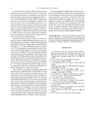
![2 M. ENDO al.
et
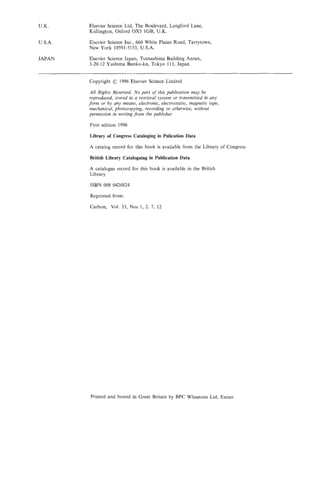
Fig. 1. Comparative preparation methods for micrometer
size fibrous carbon and carbon nanotubes as one-dimensional
forms of carbon.
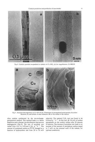
methods give similar structures, in which ultra-fine
catalytic particles are encapsulated in the tubule tips
(Fig. 2). Continued pyrolytic deposition occurs on the
initially formed thin carbon fibers causing thickening
(ca. 10 pm diameter, Fig. 3a). Substrate catalyzed fi-
bers tend to be thicker and the floating technique pro-
duces thinner fibers (ca. 1 pm diameter). This is due
to the shorter reaction time that occurs in the fluid-
ized method (Fig. 3b). Later floating catalytic meth-
ods are useful for large-scale fiber production and,
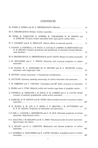
thus, VGCFs should offer a most cost-effective means Fig. 3. Vapor-grown carbon fibers obtained by substrate
of producing discontinuous carbon fibers. These method with diameter ca. 10 pm (a) and those by floating cat-
VGCFs offer great promise as valuable functional car- alyst method (b) (inserted, low magnification).
bon filler materials and should also be useful in car-
bon fiber-reinforced plastic (CFRP) production. As
seen in Fig. 3b even in the “as-grown” state, carbon 3. PREPARATION OF VGCFs AND PCNTs
particles are eliminated by controlling the reaction
conditions. This promises the possibility of producing The PCNTs in this study were prepared using
pure ACNTs without the need for separating spheroidal the same apparatus[9] as that employed to produce
carbon particles. Hitherto, large amounts of carbon VGCFs by the substrate method[l0,15]. Benzene va-
particles have always been a byproduct of nanotube por was introduced, together with hydrogen, into a ce-
production and, so far, they have only been eliminated ramic reaction tube in which the substrate consisted
by selective oxidation[l4]. This has led to the loss of of a centrally placed artificial graphite rod. The tem-
significant amounts of nanotubes - ca. 99%. perature of the furnace was maintained in the 1000°C
range. The partial pressure of benzene was adjusted
to be much lower than that generally used for the
preparation of VGCFs[lO,lS] and, after one hour
decomposition, the furnace was allowed to attain
room temperature and the hydrogen was replaced by
argon. After taking out the substrate, its surface was
scratched with a toothpick to collect the minute fibers.
Subsequently, the nanotubes and nanoscale fibers
were heat treated in a carbon resistance furnace un-
der argon at temperatures in the range 2500-3000°C
for ca. 10-15 minutes. These as-grown and sequen-
tially heat-treated PCNTs were set on an electron mi-
croscope grid for observation directly by HRTEM at
400kV acceleration voltage.
It has been observed that occasionally nanometer
scale VGCFs and PCNTs coexist during the early
Fig. 2. Vapour-grown carbon fiber showing relatively early stages of VGCF processing (Fig. 4). The former tend
stage of growth; at the tip the seeded Fe catalytic particle is to have rather large hollow cores, thick tube walls and
encapsulated. well-organized graphite layers. On the other hand,](https://image.slidesharecdn.com/13709313-carbon-nanotubes-120928071547-phpapp01/85/13709313-carbon-nanotubes-15-320.jpg)
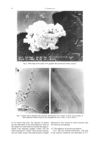
![Pyrolytic carbon nanotubes from vapor-grown carbon fibers 3
a t
b
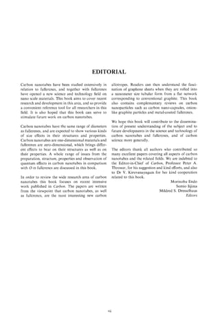
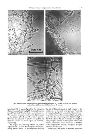
Fig. 5 . Heat-treated pyrolytic carbon nanotube and enlarged
one (inserted), without deposited carbon.
This results in well-organized multi-walled concentric
graphite tubules. The interlayer spacing (0.34 nm) is
slightly wider on average than in the case of thick
VGCFs treated at similar temperatures. This small in-
crease might be due to the high degree of curvature of
the narrow diameter nanotubes which appears to pre-
vent perfect 3-dimensional stacking of the graphitic
layers[ 16,171. PCNTs and VGCFs are distinguishable
Fig. 4. Coexisting vapour-grown carbon fiber, with thicker
diameter and hollow core, and carbon nanotubes, with thin- by the sizes of the well-graphitized domains; cross-
ner hollow core, (as-grown samples). sections indicate that the former are characterized by
single domains, whereas the latter tend to exhibit mul-
tiple domain areas that are small relative to this cross-
PCNTs tend to have very thin walls consisting of only sectional area. However, the innermost part of some
a few graphitic cylinders. Some sections of the outer VGCFs (e.g., the example shown in Fig. 5 ) may often
surfaces of the thin PCNTs are bare, whereas other consist of a few well-structured concentric nanotubes.
sections are covered with amorphous carbon depos- Theoretical studies suggest that this “single grain” as-
its (as is arrowed region in Fig. 4a). TEM images of pect of the cross-sections of nanotubes might give rise
the tips of the PCNTs show no evidence of electron to quantum effects. Thus, if large scale real-space
beam opaque metal particles as is generally observed super-cell concepts are relevant, then Brillouin zone-
for VGCF tips[lO,l5]. The large size of the cores and foiding techniques may be applied to the description
the presence of opaque particles at the tip of VGCFs of dispersion relations for electron and phonon dy-
suggests possible differences between the growth namics in these pseudo one-dimensional systems.
mechanism for PCNTs and standard VGCFs[7-91. A primary nanotube at a very early stage of thick-
The yield of PCNTs increases as the temperature and ening by pyrolytic carbon deposition is depicted in
the benzene partial pressure are reduced below the op- Figs. 6a-c; these samples were: (a) as-grown and (b),
timum for VGCF production (i.e., temperature ca. (c) heat treated at 2500°C. The pyrolytic coatings
1000°-11500C). The latter conditions could be effec- shown are characteristic features of PCNTs produced
tive in the prevention or the minimization of carbon by the present method. The deposition of extra car-
deposition on the primary formed nanotubules. bon layers appears to occur more or less simultane-
ously with nanotube longitudinal growth, resulting in
spindle-shaped morphologies. Extended periods of py-
4. STRUCTURES OF PCNTs
rolysis result in tubes that can attain diameters in the
Part of a typical PCNT (ca. 2.4 nm diameter) af- micron range (e.g., similar to conventional (thick)
ter heat treatment at 2800°C for 15 minutes is shown VGCFs[lO]. Fig. 6c depicts a 002 dark-field image,
in Fig. 5. It consists of a long concentric graphite tube showing the highly ordered central core and the outer
with interlayer spacings ca. 0.34 nm-very similar in inhomogeneously deposited polycrystalline material
morphology to ACNTs[ 1,3]. These tubes may be very (bright spots). It is worthwhile to note that even the
long, as long as 100 nm or more. It would, thus, ap- very thin walls consisting of several layers are thick
pear that PCNTs, after heat treatment at high temper- enough to register 002 diffraction images though they
atures, become graphitic nanotubes similar to ACNTs. are weaker than images from deposited crystallites on
The heat treatment has the effect of crystallizing the the tube.
secondary deposited layers, which are usually com- Fig. 7a,b depicts PCNTs with relatively large diam-
posed of rather poorly organized turbostratic carbon. eters (ca. 10 nm) that appear to be sufficiently tough](https://image.slidesharecdn.com/13709313-carbon-nanotubes-120928071547-phpapp01/85/13709313-carbon-nanotubes-16-320.jpg)
![4 M. ENDOet al.
Fig. 7. Bent and twisted PCNT (heat treated at 2500T).
Fig. 6 . PCNTs with partially deposited carbon layers (arrow
indicates the bare PCNT), (a) as-grown, (b) partially exposed
nanotube and (c) 002 dark-field image showing small crys-
tallites on the tube and wall of the tube heat treated at
2500°C.
and flexible to bend, twist, or kink without fractur-
ing. The basic structural features and the associated
mechanical behavior of the PCNTs are, thus, very dif-
ferent from those of conventional PAN-based fibers
as well as VGCFs, which tend to be fragile and easily
broken when bent or twisted. The bendings may occur
at propitious points in the graphene tube network[l8].
Fig. 8a,b shows two typical types of PCNT tip
morphologies. The caps and also intercompartment di-
aphragms occur at the tips. In general, these consist
of 2-3 concentric layers with average interlayer spac-
ing of ca. 0.38 nm. This spacing is somewhat larger
than that of the stackings along the radial direction,
presumably (as discussed previously) because of sharp
curvature effects. As indicated in Fig. 9, the conical
shapes have rather symmetric cone-like shells. The an-
gle, ca. 20°, is in good agreement with that expected
for a cone constructed from hexagonal graphene
sheets containing pentagonal disclinations -as is
Fig. 9e. Ge and Sattler[l9] have reported nanoscale
conical carbon materials with infrastructure explain-
able on the basis of fullerene concepts. STM measure- Fig. 8. The tip of PCNTs with continuous hollow core (a)
ments show that nanocones, made by deposition of and the cone-like shape (b) (T indicates the toroidal struc-
very hot carbon on HOPG surfaces, often tend to ture shown in detail in Fig. 11).](https://image.slidesharecdn.com/13709313-carbon-nanotubes-120928071547-phpapp01/85/13709313-carbon-nanotubes-17-320.jpg)
![Pyrolytic carbon nanotubes from vapor-grown carbon fibers
(c) e =60.0° (d) e =38.9' (e) e =i9.2'
e = 180- (360/ n )cos-' [l - (n/6)] [" I
(n : number of pentagons)
Fig. 9. The possible tip structure with cone shape, in which Growth direction
the pentagons are included. As a function of the number of
4
pentagons, the cone shape changes. The shaded one with 19.2"
tip angle is the most frequently observed in PCNTs.
have an opening angle of ca. 20". Such caps may,
however, be of five possible opening angles (e.g., from
112.9" to 19.2") depending on the number of pentag-
onal disclinations clustered at the tip of the cone, as
indicated in Fig. 9[8]. Hexagons in individual tube
walls are, in general, arranged in a helical disposition
with variable pitches. It is worth noting that the small-
est angle (19.2') that can involve five pentagons is
most frequently observed in such samples. It is fre- chiralsaucture
quently observed that PCNTs exhibit a spindle-shaped
structure at the tube head, as shown in Fig. 8b. Fig. 10. Growth mechanism proposed for the helical
nanotubes (a) and helicity (b), and the model that gives the
bridge and laminated tip structure (c).
5. GROWTH MODEL OF PCNTs
In the case of the PCNTs considered here, the
growth temperature is much lower than that for small closed cage fullerenes. Based on the observation
ACNTs, and no electric fields, which might influence of open-ended tubes, Iijima et a1.[13] have discussed
the growth of ACNTs, are present. It is possible that a plausible alternative way in which such tubules might
different growth mechanisms apply to PCNT and possibly grow. The closed cap growth mechanism ef-
ACNT growth and this should be taken into consid- fectively involves the addition of extended chains of
eration. As mentioned previously, one plausible mech- sp carbon atoms to the periphery of the asymmetric
anism for nanotube growth involves the insertion of 6-pentagon cap, of the kind whose Schlegel diagram
small carbon species C,, n = 1,2,3 . . .) into a closed
( is depicted in Fig. loa, and results in a hexagonal
fullerene cap (Fig. loa-c)[ll]. Such a mechanism is re- graphene cylinder wall in which the added atoms are
lated to the processes that Ulmer et a1.[20] and McE1- arranged in a helical disposition[9,1 I] similar to that
vaney et a1.[21] have discovered for the growth of observed first by Iijima[l].](https://image.slidesharecdn.com/13709313-carbon-nanotubes-120928071547-phpapp01/85/13709313-carbon-nanotubes-18-320.jpg)
![6 M. ENDOet al.
It is proposed that during the growth of primary
tubule cores, carbon atoms, diameters, and longer lin-
ear clusters are continuously incorporated into the ac-
tive sites, which almost certainly lie in the vicinity of
the pentagons in the end caps, effectively creating he-
lical arrays of consecutive hexagons in the tube wall
as shown in Fig. 10a,b[9,11]. Sequential addition of
2 carbon atoms at a time to the wall of the helix re-
sults in a cap that is indistinguishable other than by
rotation[ll,l2]. Thus, if carbon is ingested into the
cap and wholesale rearrangement occurs to allow the
new atoms to “knit” smoothly into’ the wall, the cap
can be considered as effectively fluid and to move
in a screw-like motion leaving the base of the wall
stationary- though growing by insertion of an essen-
tially uniform thread of carbon atoms to generate a
helical array of hexagons in the wall. The example
shown in Fig. 10a results in a cylinder that has a di-
ameter (ca. 1 nm) and a 22-carbon atom repeat cycle
and a single hexagon screw pitch -the smallest arche-
typal (isolated pentagon) example of a graphene nano-
tube helix. Though this model generates a tubule that
is rather smaller than is usually the case for the PCNTs
observed in this study (the simplest of which have di-
ameters > 2-3 nm), the results are of general semi-
quantitative validity. Figure 10b,c shows the growth
mechanism diagrammatically from a side view. When
the tip is covered by further deposition of aromatic
layers, it is possible that a templating effect occurs to
form the new secondary surface involving pentagons
in the hexagonal network. Such a process would ex-
plain the laminated or stacked-cup-like morphology
observed.
In the case of single-walled nanotubes, it has been
recognized recently that transition metal particles play
a role in the initial filament growth process[23]. ACNTs
and PCNTs have many similarities but, as the vapor-
growth method for PCNTs allows greater control of
the growth process, it promises to facilitate applica-
tions more readily and is thus becoming the preferred
Fig. 11. The sealed tip of a PCNT heat treated at 2800°C
method of production. with a toroidal structure (T) and, (b) molecular graphics im-
ages of archetypal flattened toroidal model at different orien-
tations and the corresponding simulated TEM images.
6. CHARACTERISTIC TOROIDAL AND
SPINDLE-LIKE STRUCTURES OF PCNTS
In Fig. 1l a is shown an HRTEM image of part of the basis of archetypal double-walled nanotubes[24].
the end of a PCNTs. The initial material consisted of As the orientation changes, we note that the HRTEM
a single-walled nanotube upon which bi-conical interference pattern associated with the rim changes
spindle-like growth can be seen at the tip. Originally, from a line to an ellipse and the loop structures at the
this tip showed no apparent structure in the HRTEM apices remain relatively distinct. The oval patterns in
image at the as-grown state, suggesting that it might the observed and simulated HRTEM image (Fig. 1lb)
consist largely of some form of “amorphous” carbon. are consistent with one another. For this preliminary
After a second stage of heat treatment at 280O0C, the investigation a symmetric (rather than helical) wall
amorphous sheaths graphitize to a very large degree, configuration was used for simplicity. Hemi-toroidal
producing multi-walled graphite nanotubes that tend connection of the inner and outer tubes with helical
to be sealed off with caps at points where the spindle- structured walls requires somewhat more complicated
like formations are the thinnest. The sealed-off end re- dispositions of the 5/6/7 rings in the lip region. The
gion of one such PCNT with a hemi-toroidal shape is general validity of the conclusions drawn here are,
shown in Fig. 1la. however, not affected. Initial studies of the problem
In Fig. 1l b are depicted sets of molecular graph- indicated that linking between the inner and outer
ics images of flattened toroidal structures which are walls is not, in general, a hindered process.](https://image.slidesharecdn.com/13709313-carbon-nanotubes-120928071547-phpapp01/85/13709313-carbon-nanotubes-19-320.jpg)
![Pyrolytic carbon nanotubes from vapor-grown carbon fibers
The toroidal structures show interesting changes
in morphology as they become larger-at least at the
lip. The hypothetical small toroidal structure shown
in Fig. 1 l b is actually quite smooth and has an essen-
tially rounded structure[24]. As the structures become
larger, the strain tends to focus in the regions near the
pentagons and heptagons, and this results in more
prominent localized cusps and saddle points. Rather
elegant toroidal structures with Dnhand Dndsymme-
try are produced, depending on whether the various
paired heptagodpentagon sets which lie at opposite
ends of the tube are aligned or are offset. In general,
they probably lie is fairly randomly disposed positions.
Chiral structures can be produced by off-setting the
pentagons and heptagons. In the D5dstructure shown
in Fig. 11 which was developed for the basic study, the
walls are fluted between the heptagons at opposite
ends of the inner tube and the pentagons of the outer
wall rim[l7]. It is interesting to note that in the com-
puter images the localized cusping leads to variations
in the smoothness of the image generated by the rim,
though it still appears to be quite elliptical when
viewed at an angle[ 171. The observed image appears
to exhibit variations that are consistent with the local- B
ized cusps as the model predicts. c k
In this study, we note that epitaxial graphitization Spinale-shapemodel
is achieved by heat treatment of the apparently mainly
Fig. 12. As-grown PCNTs with partially thickened spindle
amorphous material which surrounds a single-walled shape (a) and the proposed structural model for spindle par-
nanotube[ 171. As well as bulk graphitization, localized ticles including 12 pentagons in hexagon cage (b).
hemi-toroidal structures that connect adjacent walls
have been identified and appear to be fairly common
in this type of material. This type of infrastructure ber of pentagons as required by variants of Euler’s
may be important as it suggests that double walls may Law. Hypothetical structural models for these spin-
form fairly readily. Indeed, the observations suggest dles are depicted in Fig. 12. It is possible that simi-
that pure carbon rim-sealed structures may be readily lar two-stage growth processes occur in the case of
produced by heat treatment, suggesting that the future ACNTs but, in general, the secondary growth appears
fabrication of stabilized double-walled nanoscale to be intrinsically highly epitaxial. This may be be-
graphite tubes in which dangling bonds have been cause in the ACNT growth case only carbon atoms are
eliminated is a feasible objective. It will be interesting involved and there are fewer (non-graphitizing) alter-
to prove the relative reactivities of these structures for native accretion pathways available. It is likely that
their possible future applications in nanoscale devices epitaxial growth control factors will be rather weak
(e.g., as quantum wire supports). Although the cur- when secondary deposition is very fast, and so thin
vatures of the rims appear to be quite tight, it is clear layers may result in poorly ordered graphitic structure
from the abundance of loop images observed, that the in the thicker sections. It appears that graphitization
occurrence of such turnovers between concentric cylin- of this secondary deposit that occurs upon heat treat-
ders with a gap spacing close to the standard graphite ment may be partly responsible for the fine structure
interlayer spacing is relatively common. Interestingly, such as compartmentalization, as well as basic tip
the edges of the toroidal structures appear to be readily morphology[ 171.
visible and this has allowed us to confirm the relation-
ship between opposing loops. Bulges in the loops of
7. VGCFs DERIVED FROM NANOTUBES
the kind observed are simulated theoretically[ 171.
Once one layer has formed (the primary nanotube In Fig. 13 is shown the 002 lattice images of an “as-
core), further secondary layers appear to deposit with formed” very thin VGCF. The innermost core diam-
various degrees of epitaxial coherence. When inhomo- eter (ca. 20 nm as indicated by arrows) has two layers;
geneous deposition occurs in PCNTs, the thickening it is rather straight and appears to be the primary
has a characteristic spindle shape, which may be a nanotube. The outer carbon layers, with diameters ca.
consequence of non-carbon impurities which impede 3-4 nm, are quite uniformly stacked parallel to the
graphitization (see below)- this is not the case for central core with 0.35 nm spacing. From the difference
ACNTs were growth takes place in an essentially all- in structure as well as the special features in the me-
carbon atmosphere, except, of course, for the rare gas. chanical strength (as in Fig. 7) it might appear possi-
These spindles probably include the appropriate num- ble that the two intrinsically different types of material](https://image.slidesharecdn.com/13709313-carbon-nanotubes-120928071547-phpapp01/85/13709313-carbon-nanotubes-20-320.jpg)
![8 et
M. ENDO al.
of ca. 10 nm (white arrow), observed by field emission
scanning electron microscopy (FE-SEM)[25]. It is,
thus, suggested that at least some of the VGCFs start
as nanotube cores, which act as a substrate for sub-
sequent thickening by deposition of secondary pyro-
lytic carbon material, as in the catalytically primarily
grown hollow fiber. In Fig. 14b is also shown the TEM
image corresponding to the extruded nanotube from
a very thin fiber. It is clearly observed that the exposed
nanotube is continuing into the fiber as a central hol-
low core, as indicated by the white arrow in the figure.
It is interesting that, as indicated before (in Fig. 14a),
the core is more flexible than the pyrolytic part, which
is more fragile.
Fig. 13. HRTEM image of an as-grown thick PCNT. 002
lattice image demonstrates the innermost hollow core (core 8 CONCLUSION
.
diam. 2.13 nm) presumably corresponding to the “as-formed”
Pyrolytic carbon nanotubes (PCNTs), which grow
nanotube. The straight and continuous innermost two fringes
similar to Fig. 5 are seen (arrow). during hydrocarbon pyrolysis, appear to have struc-
tures similar to those obtained by arddischarge tech-
niques using graphite electrodes (ACNTs). The PCNTs
tend to exhibit a characteristic thickening feature due
involved might be separated by pulverizing the VGCF
to secondary pyrolytic carbon deposition. Various tip
material.
morphologies are observed, but the one most fre-
In Fig. 14a, a ca. 10 wm diameter VGCF that has
quently seen has a 20” opening angle, suggesting that,
been broken in liquid nitrogen is depicted, revealing
in general, the graphene conical tips possess a cluster
the cylindrical graphitic nanotube core with diameter
of five pentagons that may be actively involved in tube
growth. PCNTs with spindle-like shapes and that have
conical caps at both ends are also observed, for which
a structural model is proposed. The spindle-like struc-
tures observed for the secondary growth thickening
that occurs in PCNTs may be a consequence of the
lower carbon content present in the growth atmo-
sphere than occurs in the case of ACNT growth. Pos-
sible structural models for these spindles have been
discussed. The longitudinal growth of nanotubes ap-
pears to occur at the hemi-spherical active tips and this
process has been discussed on the basis of a closed cap
mechanism[9,11]. The PCNTs are interesting, not only
from the viewpoint of the fundamental perspective
that they are very interesting giant fullerene structures,
but also because they promise to be applications in
novel strategically important materials in the near fu-
ture. PCNT production appears, at this time, more
readily susceptible to process control than is ACNT
production and, thus, their possible value as fillers in
advanced composites is under investigation.
Acknowledgements-Japanese authors are indebted to M. S.
Dresselhaus and G. Dresselhaus of MIT and to A. Oberlin
of Laboratoire Marcel Mathieu (CNRS) for their useful dis-
cussions and suggestions. HWK thanks D. R. M. Walton for
help and the Royal Society and the SERC (UK) for support.
Part of the work by ME is supported by a grant-in-aid for
scientific research in priority area “carbon cluster” from the
Ministry. of Education, Science and Culture, Japan.
Fig. 14. PCNTs (white arrow) appeared after breakage of
VGCF, (a) FE-SEM image of broken VGCF, cut in liquid ni- REFERENCES
trogen and (b) HRTEM image showing the broken part ob-
served in very thin VGCF. The nanotube is clearly observed 1 . S. Iijima, Nature 354, 56 (1991).
and this indicates that thin VGCF grow from nanometer core 2. H. W. Kroto, J. R. Heath, S. C .O’Brien, R. F. Curl, and
by thickening. R. E. Samlley, Nature 318, 162 (1985).](https://image.slidesharecdn.com/13709313-carbon-nanotubes-120928071547-phpapp01/85/13709313-carbon-nanotubes-21-320.jpg)

![ELECTRIC EFFECTS IN NANOTUBE GROWTH
DANIEL COLBERT RICHARD SMALLEY
T. and E.
Rice Quantum Institute and Departments of Chemistry and Physics, MS 100,
Rice University, Houston, TX 77251-1892, U.S.A.
(Received 3 April 1995; accepted 7 April 1995)
Abstract-We present experimental evidence that strongly supports the hypothesis that the electric field
of the arc plasma is essential for nanotube growth in the arc by stabilizing the open tip structure against
closure. By controlling the temperature and bias voltage applied to a single nanotube mounted on a mac-
roscopic electrode, we find that the nanotube tip closes when heated to a temperature similar to that in
the arc unless an electric field is applied. We have also developed a more refined awareness of “open”
tips in which adatoms bridge between edge atoms of adjacent layers, thereby lowering the exothermicity
in going from the open to the perfect dome-closed tip. Whereas realistic fields appear to be insufficient
by themselves to stabilize an open tip with its edges completely exposed, the field-induced energy lower-
ing of a tip having adatom spot-welds can, and indeed in the arc does, make the open tip stable relative
to the closed one.
Key Words-Nanotubes, electric field, arc plasma
1. INTRODUCTION the electric field concentrates, and never in the soots
condensed from the carbon vapor exiting the arcing
As recounted throughout this special issue, significant
region, suggest a vital role for the electric field. Fur-
advances in illuminating various aspects of nanotube
thermore, the field strength at the nanotube tips is very
growth have been made[l,2] since Iijima’s eventful
large, due both to the way the plasma concentrates
discovery in 1991;[3] these advances are crucial to
most of the potential drop in a very short distance
gaining control over nanotube synthesis, yield, and
above the cathode, and to the concentrating effects of
properties such as length, number of layers, and he-
the field at the tips of objects as small as nanotubes.
licity. The carbon arc method Iijima used remains the
The field may be on the order of the strength required
principle method of producing bulk amounts of qual-
to break carbon-carbon bonds, and could thus dra-
ity nanotubes, and provides key clues for their growth
matically effect the tip structure.
there and elsewhere. The bounty of nanotubes depos-
In the remaining sections of this paper, we describe
ited on the cathode (Ebbesen and Ajayan have found
the experimental results leading to confirmation of the
that up to 50% of the deposited carbon is tubular[4])
stabilizing role of the electric field in arc nanotube
is particularly puzzling when one confronts the evi-
growth. These include: relating the plasma structure
dence of UgarteI.51 that tubular objects are energeti-
to the morphology of the cathode deposit, which re-
cally less stable than spheroidal onions.
vealed that the integral role of nanotubes in sustain-
It is largely accepted that nanotube growth occurs
ing the arc plasma is their field emission of electrons
at an appreciable rate only at open tips. With this con-
into the plasma; studying the field emission character-
straint, the mystery over tube growth in the arc redou-
istics of isolated, individual arc-grown nanotubes; and
bles when one realizes that the cathode temperature
the discovery of a novel production of nanotubes that
(-3000°C) is well above that required to anneal car-
significantly alters the image of the “open” tip that the
bon vapor to spheroidal closed shells (fullerenes and
arc electric field keeps from closing.
onions) with great efficiency. The impetus to close is,
just as for spheroidal fullerenes, elimination of the
dangling bonds that unavoidably exist in any open 2. NANOTUBES AS FIELD EMITTERS
structure by incorporation of pentagons into the hex-
agonal lattice. Thus, a central question in the growth Defects in arc-grown nanotubes place limitations
of nanotubes in the arc is: How do they stay open? on their utility. Since defects appear to arise predom-
One of us (RES) suggested over two years ago161 inantly due to sintering of adjacent nanotubes in the
that the resolution to this question lies in the electric high temperature of the arc, it seemed sensible to try
field inherent to the arc plasma. As argued then, nei- to reduce the extent of sintering by cooling the cath-
ther thermal nor concentration gradients are close to ode better[2]. The most vivid assay for the extent of
the magnitudes required to influence tip annealing, sintering is the oxidative heat purification treatment
and trace impurities such as hydrogen, which might of Ebbesen and coworkers[7], in which amorphous
keep the tip open, should have almost no chemisorption carbon and shorter nanoparticles are etched away be-
residence time at 3000°C. The fact that well-formed fore nanotubes are substantially shortened. Since, as
nanotubes are found only in the cathode deposit, where we proposed, most of the nanoparticle impurities orig-
11](https://image.slidesharecdn.com/13709313-carbon-nanotubes-120928071547-phpapp01/85/13709313-carbon-nanotubes-24-320.jpg)
![12 D. T.COLBERT R. E. SMALLEY
and
inated as broken fragments of sintered nanotubes, the bias was controlled relative to an opposing electrode,
amount of remaining material reflects the degree of and if desired, reactive gases could be introduced.
sintering. Two classes of emission behavior were found. An
Our examinations of oxygen-purified deposits led inactivated state, in which the emission current in-
to construction of a model of nanotube growth in the creased upon laser heating at a fixed potential bias,
arc in which the nanotubes play an active role in sus- was consistent with well understood thermionic field
taining the arc plasma, rather than simply being a emission models. Figure l a displays the emission cur-
passive product[2]. Imaging unpurified nanotube-rich rent as the laser beam is blocked and unblocked, re-
arc deposit from the top by scanning electron micros- vealing a 300-fold thermal enhancement upon heating.
copy (SEM) revealed a roughly hexagonal lattice of Etching the nanotube tip with oxygen while the tube
50-micron diameter circles spaced -50 microns apart. was laser heated to 1500°C and held at -75 V bias
After oxidative treatment the circular regions were seen produced an activated state with exactly the opposite
to have etched away, leaving a hole. More strikingly, behavior, shown in Fig. 2b; the emission current in-
when the deposit was etched after being cleaved ver- creased by nearly two orders of magnitude when the
tically to expose the inside of the deposit, SEM imag- laser beam was blocked! Once we eliminated the pos-
ing showed that columns the diameter of the circles sibility that species chemisorbed on the tip might be
had been etched all the way from the top to the bot- responsible for this behavior, the explanation had to
tom of the deposit, leaving only the intervening mate- invoke a structure built only of carbon whose sharp-
rial. Prior SEM images of the column material (zone 1) ness would concentrate the field, thus enhancing the
showed that the nanotubes there were highly aligned emission current. As a result of these studies[9], a dra-
in the direction of the electric field (also the direction matic and unexpected picture has emerged of the
of deposit growth), whereas nanotubes in the sur- nanotube as field emitter, in which the emitting source
rounding region (zone 2) lay in tangles, unaligned with is an atomic wire composed of a single chain of car-
the field[2]. Since zone 1 nanotubes tend to be in much bon atoms that has been unraveled from the tip by the
greater contact with one another, they are far more force of the applied electric field (see Fig. 2). These
susceptible to sintering than those in zone 2, resulting carbon wires can be pulled out from the end of the
in the observed preferential oxidative etch of zone 1. nanotube only once the ragged edges of the nanotube
These observations consummated in a growth layers have been exposed. Laser irradiation causes the
model that confers on the millions of aligned zone 1 chains to be clipped from the open tube ends, result-
nanotubes the role of field emitters, a role they play ing in low emission when the laser beam is unblocked,
so effectively that they are the dominant source of but fresh ones are pulled out once the laser is blocked.
electron injection into the plasma. In response, the This unraveling behavior is reversible and reproducible.
plasma structure, in which current flow becomes con-
centrated above zone 1, enhances and sustains the
4. THE STRUCTURE OF AN OPEN NANOTUBE TIP
growth of the field emission source-that is, zone 1
nanotubes. A convection cell is set up in order to al- A portion of our ongoing work focusing on sphe-
low the inert helium gas, which is swept down by col- roidal fderenes, particularly metallofullerenes, utilized
lisions with carbon ions toward zone 1, to return to the same method of production as was originally used
the plasma. The helium flow carries unreacted carbon in the discovery of fullerenes, the laser-vaporization
feedstock out of zone 1, where it can add to the grow- method, except for the modification of placing the
ing zone 2 nanotubes. In the model, it is the size and flow tube in an oven to create better annealing con-
spacing of these convection cells in the plasma that de- ditions for fullerene formation. Since we knew that at
termine the spacing of the zone l columns in a hex- the typical 1200°C oven temperature, carbon clusters
agonal lattice. readily condensed and annealed to spheroidal fuller-
enes (in yields close to 40%), we were astonished to
find, upon transmission electron micrographic exam-
3. FIELD EMISSION FROM AN ATOMIC WIRE
ination of the collected soots, multiwalled nanotubes
Realization of the critical importance played by with few or no defects up to 300 nm long[lO]! How,
emission in our arc growth model added impetus to we asked ourselves, was it possible for a nanotube
investigations already underway to characterize nano- precursor to remain open under conditions known to
tube field emission behavior in a more controlled man- favor its closing, especially considering the absence of
ner. We had begun working with individual nanotubes extrinsic agents such as a strong electric field, metal
in the hope of using them as seed crystals for con- particles, or impurities to hold the tip open for growth
trolled, continuous growth (this remains an active and elongation?
goal). This required developing techniques for harvest- The only conclusion we find tenable is that an in-
ing nanotubes from arc deposits, and attaching them trinsic factor of the nanotube was stabilizing it against
with good mechanical and electrical connection to closure, specifically, the bonding of carbon atoms to
macroscopic manipulators[2,8,9]. The resulting nano- edge atoms of adjacent layers, as illustrated in Fig. 2.
electrode was then placed in a vacuum chamber in Tight-binding calculations[l 1J indicate that such sites
which the nanotube tip could be heated by applica- are energetically preferred over direct addition to the
tion of Ar+-laser light (514.5 nm) while the potential hexagonal lattice of a single layer by as much as 1.5 eV](https://image.slidesharecdn.com/13709313-carbon-nanotubes-120928071547-phpapp01/85/13709313-carbon-nanotubes-25-320.jpg)
![Electric effects in nanotube growth 13
Laser
On
Laser
Off
1
0 0 25 50 75 100
Time (sec) Time (sec)
Fig. 1. Field emission data from a mounted nanotube. An activated nanotube emits a higher current when
heated by the laser than when the laser beam is blocked (a). When activated by exposing the nanotube
to oxygen while heating the tip, this behavior is reversed, and the emission current increases dramatically
when the laser is blocked. The activated state can also be achieved by laser heating while maintaining a
bias voltage of -75 V. Note that the scale of the two plots is different; the activated current is always higher
than the inactivated current. As discussed in the text, these data led to the conclusion that the emitting
feature is a chain of carbon atoms pulled from a single layer of the nanotube-an atomic wire.
per adatom. We also knew at this time that the electric
field of the arc was not by itself sufficient to stabilize
an open tip having no spot-welds against closure[l2],
so we now regard these adatom "spot-welds'' as a nec-
essary ingredient to explain growth of nanotubes in the
oven laser-vaporization method as well as in the arc,
and probably other existing methods of nanotube
production.
5. ELECTRIC FIELD STABILIZATION
OF AN OPEN NANOTUBE TIP
The proposal that the essential feature of arc
growth was the high electric field that concentrates at
the growing nanotube tip prompted ab initio structure
calculations[ 12,131 to assess this hypothesis quantita-
tively. These calculations, which were performed for
single-walled nanotubes in high applied electric fields,
showed that field-induced lowering of the open tip en-
ergy is not sufficient to make the open conformation
more stable than the closed tip at any field less than
10 V/A. Whereas single-walled objects certainly an-
Fig. 2. A graphic of a nanotube showing a pulled-out atomic neal and at 12000c form 'pheroidal
t'
wire and several stabilizing spot-welds. Only two layers have fullerenes[l4,151, open multiwalled species have other
been shown for clarity, although typical multiwalled nano- alternatives, and thus may be auite different in this
tubes have 10-15 layers. The spot-weld adatoms shown be- respect. In particular, for multiwalled species, adatom
tween layers stabilize the open tip conformation against
closure. The atomic wire shown was previously part of the
spot-welds may be sufficiently stabilizing to allow
hexagonal lattice of the inner layer. It is prevented from pull- growth and before succumbing to the
ing out further by the spot-weld at its base. conformation.](https://image.slidesharecdn.com/13709313-carbon-nanotubes-120928071547-phpapp01/85/13709313-carbon-nanotubes-26-320.jpg)
![CATALYTIC PRODUCTION AND PURIFICATION OF
NANOTUBULES HAVING FULLERENE-SCALE DIAMETERS
V. I[vANov,~** A. FONSECA,"
J. B.NAGY,"+LUCAS," LAMBIN," BERNAERTS~
A. P. D. and
X. B. ZHANG~
"Institute for Studies of Interface Science, FacultCs Universitaires Notre Dame de la Paix,
61 rue de Bruxelles, B-5000 Namur, Belgium
bEMAT,University of Antwerp (RUCA),Groenenborgerlaan 171, B-2020 Antwerp, Belgium
(Received 25 July 1994; accepted in revisedform 13 March 1995)
Abstract-Carbon nanotubules were produced in a large amount by catalytic decomposition of acetylene
in the presence of various supported transition metal catalysts. The influence of different parameters such
as the nature of the support, the size of active metal particles and the reaction conditions on the formation
of nanotubules was studied. The process was optimized towards the production of nanotubules having
the same diameters as the fullerene tubules obtained from the arc-hscharge method. The separation of
tubules from the substrate, their purification and opening were also investigated.
Key Words-Nanotubules, fullerenes, catalysis.
1. INTRODUCTION production. The synthesis of the nanotubules of vari-
ous diameters, length and structure as dependent on
The catalytic growth of graphitic carbon nanofibers
the parameters of the method is studied in detail. The
during the decomposition of hydrocarbons in the
elimination of amorphous carbon is also investigated.
presence of either supported or unsupported metals,
has been widely studied over the last years[ 1-61.
The main goal of these studies was to avoid the 2. EXPERIMENTAL
formation of "filamentous" carbon, which strongly
The catalytic decomposition of acetylene was car-
poisons the catalyst. More recently, carbon tubules
ried out in a flow reactor at atmospheric pressure. A
of nanodiameter were found to be a byproduct of
ceramic boat containing 20-100 mg of the catalyst
arc-discharge production of fullerenes [7]. Their cal-
was placed in a quartz tube (inner diameter 4-10 mm,
culated unique properties such as high mechanical
length 60-100 cm). The reaction mixture of 2.5-10%
strength[ 81, their capillary properties [91 and their
CzH2 (Alphagaz, 99.6%) in N, (Alphagaz, 99.99%)
remarkable electronic structure [ 10-121 suggest a
was passed over the catalyst bed at a rate of
wide range of potential uses in the future. The catalyti-
0.15-0.59 mol C2H2g-lh-' for several hours at tem-
cally produced filaments can be assumed to be ana-
peratures in the range 773-1073 K.
logous to the nanotubules obtained from arc-
The catalysts were prepared by the following
discharge and hence to possess similar properties [51,
methods. Graphite supported samples containing
they can also be used as models of fullerene nano-
0.5-10 wt% of metal were prepared by impregnation
tubes. Moreover, advantages over arc-discharge fibers
of natural graphite flakes (Johnson-Matthey, 99.5%)
include a much larger length (up to 50pm) and a
with the solutions of the metal salts in the appropriate
relatively low price because of simpler preparation.
concentrations: Fe or Co oxalate (Johnson-Matthey),
Unfortunately, carbon filaments usually obtained in
Ni or Cu acetate (Merck). Catalysts deposited on
catalytic processes are rather thick, the thickness
SiO, were obtained by porous impregnation of
being related to the size of the active metal particles.
silica gel (with pores of 9 nm, ,S 600 m2g1, Janssen
The graphite layers of as-made fibres contain many
Chimica) with aqueous solutions of Fe(IJ1) or Co(I1)
defects. These filaments are strongly covered with
nitrates in the appropriate amounts to obtain 2.5
amorphous carbon, which is a product of the thermal
wt% of metal or by ion-exchange-precipitation of the
decomposition of hydrocarbons [ 131. The catalytic
same silica gel with 0.015 M solution of Co(I1) nitrate
formation of thin nanotubes was previously
(Merck) following a procedure described in Ref. [ 151.
reported[ 141. In this paper we present the detailed
The catalyst prepared by the latter method had 2.1
description of the catalytic deposition of carbon on
wt% of Co. All samples were dried overnight at 403 K
various well-dispersed metal catalysts. The process
and then calcined for 2 hours at 173 K in flowing
has been optimized towards the large scale nanotubes nitrogen and reduced in a flow of 10% H, in Nz at
773 K for 8 hours.
*To whom all correspondence should be addressed.
+Permanent address: Laboratory of Organic Catalysis, Zeolite-supported Co catalyst was synthesized
Chemistry Department, Moscow State University, 119899, by solid-state ion exchange using the procedure
Moscow, Russia. described by Kucherov and SlinkinC16, 171. COO
15](https://image.slidesharecdn.com/13709313-carbon-nanotubes-120928071547-phpapp01/85/13709313-carbon-nanotubes-28-320.jpg)
![16 V.IVANOV
et al.
was mixed in an agath morter with HY zeolite. The ite sheets on the latter catalysts. The tubular filaments
product was pressed, crushed, dried overnight at on Fe- and Co-graphite sometimes possessed well-
403 K and calcined in air for 1 hour at 793 K, then crystalline graphite layers. In the same growth batch
for 1 hour at 1073 K and after cooling for 30 minutes we also observed a large amount of non-hollow
in flowing nitrogen, the catalyst was reduced in a filaments with a structure similar to that observed
flow of 10% H2 in N2 for 3 hours at 673K. The on Cu and Ni catalysts.
concentration of COO was calculated in order to In general, encapsulated metal particles were
obtain 8 wt% of Co in the zeolite. observed . on all graphite-supported catalysts.
The list of studied catalysts and some characteris- According to Ref. [4] it can be the result of a rather
tics are given in Table 1. weak metal-graphite interaction. We mention the
The samples were examined before and after catal- existence of two types of encapsulated metal particles:
ysis by SEM (Philips XL 20) and HREM by both a those enclosed in filaments (Fig. 1) and those encap-
JEOL 200 CX operating at 200 kV and a JEOL 4000 sulated by graphite. It is interesting to note that
EX operating at 40OkV. The specimens for TEM graphite layers were parallel to the surface of the
were either directly glued on copper grids or dispersed encapsulated particles.
in acetone by ultrasound, then dropped on the holey As was found in Ref. [131, the method of catalytic
carbon grids. decomposition of acetylene on graphite-supported
'H-NMR studies were performed on a Bruker catalysts provides the formation of very long (50 pm)
MSL-400 spectrometer operating in the Fourier tubes. We also observed the formation of filaments
transform mode, using a static multinuclei probehead up to 60pm length on Fe- and Co-graphite. In all
operating at 400.13 MHz. A pulse length of 1 ps is cases these long tubules were rather thick. The thick-
used for the IH 90"flip angle and the repetition time ness varied from 40 to 100 nm. Note that the disper-
used (1 second) is longer than five times T,, ('H) of sion of metal particles varied in the same range. Some
the analyzed samples. metal aggregates of around 500 nm in diameter were
also found after the procedure of catalyst pretreat-
ment (Fig. 2). Only a very small amount of thin
3. RESULTS AND DISCUSSION
(20-40 nm diameter) tubules was observed.
3.1 Catalyst support The as-produced filaments were very strongly
The influence of the support on the mechanism of covered by amorphous carbon produced by thermal
filament formation was previously described[1-41. pyrolysis of acetylene. The amount of amorphous
The growth process was shown to be strongly depen- carbon varied with the reaction conditions. It
dent on the catalyst-support interaction. In the first increased with increasing reaction temperature and
stage of our studies we performed the acetylene with the percentage of acetylene in the reaction
decomposition reaction over graphite supported mixture. Even in optimal conditions not less than
metals. This procedure was reported in Ref. [ 131 as 50% of the carbon was deposited in the form of
promising to obtain a large amount of long nano- amorphous carbon in accordance with[ 131.
tubes. The reaction was carried out in the presence As it was established by Geus et aL[l8, 191 the
of either Cu, Ni, Fe or Co supported particles. All of decrease of the rate of carbon deposition is a positive
these metals showed a remarkable activity in filament factor for the growth of fibres on metal catalysts.
formation (Fig. 1).The structure of the filaments was SiO, is an inhibitor of carbon condensation as was
different on the various metals. We have observed shown in Ref. [20]. This support also provides possi-
the formation of hollow structures on the surface of bilities for the stabilization of metal dispersion. Co
Co and Fe catalysts. On Cu and Ni, carbon was and Fe, i.e. the metals that give the best results for
deposited in the form of irregular fibres. The detailed the tubular condensation of carbon on graphite
observation showed fragments of turbostratic graph- support, were introduced on the surface of silica gel
Table 1. Method of preparation and metal content of the catalysts
Metal particle
Poae 0 Method of Metal diameteP
Sample (A) preparation (wt%) (nm)
Co-graphite - Impregnation 0.5-10 1Cb100
F-phite - Impregnation 2.5 2 100
Ni-graphite - Impregnation 2.5 2 loo
-aphite - Impregnation 2.5 2 loo
Co-SiO, 90 Ion exchange precipitation 2.1 2-2Ob
CO-HY 7.5 Solid state ion exchange 8 1-50
Co-Si0,-1 40 Pore impregnation 2.5 10-100
Co-Si02-2 90 Pore impregnation 2.5 10-100
Fe-SiO, 90 Pore impregnation 2.5 10-100
"Measured by SEM and TEM.
%e distribution of the particles was also measured (Fig. 6).](https://image.slidesharecdn.com/13709313-carbon-nanotubes-120928071547-phpapp01/85/13709313-carbon-nanotubes-29-320.jpg)
![Catalytic production and purification of nanotubules 17
Fig. 1. Carbon filaments grown after acetylene decomposition at 973 K for 5 hours on
(a) Co(2.5%)-graphite;(b) Fe-graphite; (c) Ni-graphite; (d) Cu-graphite.
by different methods. Both metals showed very similar models proposed earlier[4,18,22]. The metal outside
catalytic behaviour. Carbon was deposited on these of the support is saturated by the carbon produced
catalysts mostly in the form of filaments. TEM images by hydrocarbon decomposition, possibly in the form
of the tubules obtained on these catalysts are given of “active” carbides. The latter then decomposes on
in Fig. 3. Most of the filaments produced on silica- the surface of the metal, producing graphite layers.
supported catalysts were tubular, with well-resolved Such a situation is typical for catalysts with a weak
graphite layers. Nevertheless non-tubular filaments metal-support interaction, as in the case of graphite.
also grow in these conditions. We observed that the The zeolite support was used to create very finely
relative quantity of well-graphitized tubules was dispersed metal clusters. Metals can be localized in
higher on Co-silica than on Fe-silica catalyst. the solid-state exchanged zeolites in the small cages,
As in the case of graphite-supported catalysts, supercages or intercrystalline spaces. In fact, in accor-
some metal particles were also encapsulated by the dance with previously observed data [231, hydrogen-
deposited carbon (Fig. 4). However, the amount of ation of as-made catalysts led to the migration of
encapsulated metal was much less. Differences in the metal to the outer surface of the zeolite HY. The
nature of encapsulation were observed. Almost all sizes of metal crystallites varied in our catalyst from
encapsulated metal particles on silica-supported cata- 1 to 50 nm. We suppose that because of steric limita-
lysts were found inside the tubules (Fig. 4(a)). The tions only the metal particles at the outer surface and
probable mechanism of this encapsulation was pre- in supercages could be available for filament growth.
cisely described elsewhere[ 213. We supposed that The hydrocarbon decomposition over Co-HY pro-
they were catalytic particles that became inactive vides the formation of different graphite-related struc-
after introduction into the tubules during the growth tures (it should be noted that only a small amount
process. On the other hand, the formation of graphite of amorphous carbon was observed). Similar to the
layers around the metal in the case of graphite- previous catalysts, nanotubules of various radius and
supported catalysts can be explained on the basis of metal particles encapsulated by graphite were found](https://image.slidesharecdn.com/13709313-carbon-nanotubes-120928071547-phpapp01/85/13709313-carbon-nanotubes-30-320.jpg)
![20 et al.
V. IVANOV
ments (Fig. 7). Thus, we suppose that the formation
of graphite tubules in these conditions is a very rapid
30-
process and the thermal pyrolysis leading to the
formation of amorphous carbon does not have a
great influence. Hence, carbon nanotubules, quasi-
free from amorphous carbon, are formed.
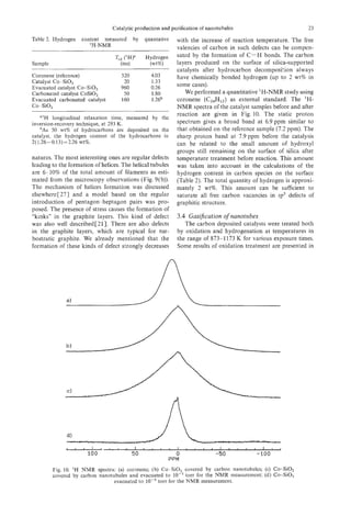
3.2.3 Reaction time. Two series of experiments
were performed in order to study the influence of the
reaction time on the characteristics of surface carbon
structures. In the first series, the hydrocarbon depos-
ition was periodically stopped, the catalyst was cooled
0-3 3-6 6-9 9-12 12-18 down under flowing nitrogen and it was removed
d, nm from the furnace. After taking a small part of the
Fig. 6. Sizedistribution of metal crystallites on the surface reaction mixture for TEM analysis, the remaining
of Co-silica made by precipitation-ionexchangemethod. amount of the catalyst was put back into the furnace
and the hydrocarbon deposition was further carried
3.2.2 Reaction temperature. The reaction tem- out under the same conditions. In the second series,
perature was vaned in the range 773-1073K. The different portions of catalyst were treated by hydro-
formation of filament structures was observed at all carbon for different times. The results were similar
studied temperatures. As has already been mentioned, for both series of catalysts. Typical images of carbon
the graphitization of carbon into the tubular struc- surface structures grown during different times are
tures on metal-supported catalysts is generally accom- shown in Fig. 8. In accordance with Ref. [4] we
panied by the formation of amorphous carbon. Both observed the dependence of the rate of filament
processes are temperature dependent. The filaments formation on the size of the catalytic particles. In the
grown at low temperature (773 K) are relatively free first (1 minute) reaction period, mostly very thin
of amorphous carbon. The amount of amorphous carbon filaments were observed as grown on the
carbon increases with increasing temperature and smallest metal particles. These filaments were very
represents about 10% of all carbon condensed on the irregular and the metal particles were generally found
external surface of the catalyst at 973 K. However, at the tips of the fibres. With increasing reaction time
crystallinity of the graphite layers in tubules also the amount of well-graphitized tubules progressively
strongly depends on the reaction temperature being increased. At the same time the average length of the
the lowest at low temperature. nanotubules increased. We need, however, to note
The average length of the tubules is not strongly that a relation exists between the lengths of the
influenced by temperature. However, the amorphous tubules and their diameters. The longest tubules are
carbon on the outer layers of filaments produced also the thickest. For instance, the tubules of
under optimal conditions is often deposited in frag- 3&60 pm length have diameters of 35-40 nm corre-
Fig.7. Graphite nanotubule on Co-SiO, with the fragments of amorphous carbon (arrowed) at the
external surface.](https://image.slidesharecdn.com/13709313-carbon-nanotubes-120928071547-phpapp01/85/13709313-carbon-nanotubes-33-320.jpg)
![22 V. IVANOV al.
et
after cooling and reheating the carbon deposited performed on metal-supported catalysts with larger
sample. Metal particles even found near the tips of and, thus, less active metal aggregates.
the tubules were always covered by graphite layers. It is also important to point out that pure cobalt
It supports the model of an “extrusion” of the carbon oxide, alone or finely dispersed in SiO, (i.e. Co-SiO,,
tubules from the surface of active particles [24]. Co-SO,-1 and Co-Si02-2 in Table l), zeolite HY,
3.2.4 Injuence of hydrogen. The influence of fullerene (i.e. C60/C70: 80/20) is at least as effective
the presence of hydrogen in the reaction mixture on as the reduced oxides for the production of nanotu-
the formation of nanofibres has been shown in various bules in our experimental conditions. In fact, the
papersC1-3, 18, 25, 261. It was postulated that the catalysts studied in this work are also active if the
presence of H2 decreases the rate of hydrocarbon hydrogenation step is not performed. This important
decomposition and as a result favours the process of point, is presently being investigated in our laboratory
carbon polycondensation over the production of fil- in order to elucidate the nature of the active catalyst
aments. However, the addition of hydrogen into the (probably a metal carbide) for the production of
mixture of acetylene and nitrogen did not give major nanotubules.
effects on the tubule formation in our case. We
suppose that the activity of metal nanoparticles on 3.3 The amount o hydrogen injlaments
f
our Co-SiO, catalyst was high enough to provide As it can be observed from the high resolution
filament formation without hydrogen addition. It images of tubules (Fig. 9(a)) their graphitic structure
differs from the previous investigations, which were is generally defective. The defects can be of different
Fig. 9. Carbon nanotubules on Co-SO,: (a) HREM image showing defects in tubules;(b) helical tubules
of various pitches between the straight tubules.](https://image.slidesharecdn.com/13709313-carbon-nanotubes-120928071547-phpapp01/85/13709313-carbon-nanotubes-35-320.jpg)
![24 V. IVANOV
et al.
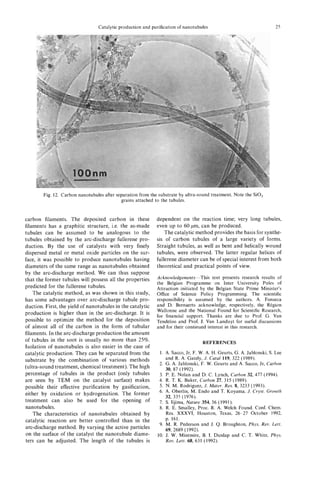
Fig. 11. Tips of carbon nanotubules grown on Co- SiO, (acetylene reaction at 973 K, 30 minutes after
oxidation in air for 30 minutes at 873, K: (a) low magnification; (b) HREM.
Fig. 11. The loss of carbon rapidly increases with the bules could be preferable in comparison with oxida-
increase of temperature. Heating of the catalysts in tion, because of the easier control in the former case.
open air for 30 minutes at 973 K leads to the total
elimination of carbon from the surface. The gasifica- 3.5 Product purijication
tion of amorphous carbon proceeds more rapidly For the physico-chemical measurements and prac-
than that of filaments. The tubules obtained after tical utilisation in some cases the purification of
oxidation of carbon-deposited catalysts during 30 nanotubules is necessary. In our particular case,
minutes at 873 K are almost free from amorphous purification means the separation of filaments from
carbon. The process of gasification of nanotubules the substrate-silica support and Co particles.
on the surface of the catalyst is easier in comparison The carbon-containing catalyst was treated by
with the oxidation of nanotubes containing soot ultra-sound (US) in acetone at different conditions.
obtained by the arc-discharge method C28, 291. This The power of US treatment, and the time and regime
can be easily explained, in agreement with Ref. [30], (constant or pulsed), were varied. Even the weakest
by the surface activation of oxygen of the gaseous treatments made it possible to extract the nanotubules
phase on Co-SiO, catalyst. from the catalyst. With the increase of the time and
The gasification of graphite layers proceeds more the power of treatment the amount of extracted
easily at the tips of the tubules and at structural carbon increased. However, we noticed limitations of
defects. Typical images of the tips of catalytically this method of purification. The quantity of carbon
produced tubules after treatment in air are presented species separated from the substrate was no more
in Fig. 11. On graphite tubules grown from Co-SiO, than 10% from all deposited carbon after the most
catalyst, two types of tip were usually observed. In powerful treatment. Moreover, the increase of power
the first, the tubules are closed by graphite layers led to the partial destruction of silica grains, which
with the metal particle inside the tubules (Fig. 4(a)). were then extracted with the tubules. As a result,
In the second type, more generally observed, the even in the optimal conditions the final product was
tubules are closed with amorphous carbon. The open- never completely free of silica (Fig. 12).
ing of tubules during oxidation could proceed on For better purification, the tubule-containing cata-
both types of tip. lyst was treated by H F (40%) over 72 hours. The
The gasification of carbon filaments by high- resulting extract was purer than that obtained after
temperature hydrogen treatment was postulated as US treatment. The addition of nitric acid also makes
involving the activation of hydrogen on the metal it possible to free the tubules of metal particles on
surfaceC31-331. We observed a very slight effect of the external surface. The conditions of the acid treat-
catalyst hydrogenation, which was visible only after ment and tubule extraction have yet to be optimized.
the treatment of carbon-deposited catalyst for 5 hours
at 1173 K. We suppose that the activation of
4. CONCLUSIONS
hydrogen in our case could proceed on the non-
covered centers of Co or, at very high temperatures, In this study we have shown that the catalytic
it could be thermal dissociation on the graphite method-carbon deposition during hydrocarbons
surface layers of tubules. The result was similar to conversion-can be widely used for nanotubule pro-
that of oxidation but the process proceeded much duction methods. By variation of the catalysts and
slower. We called it “gentle” gasification and we reaction conditions it is possible to optimize the
believe that this method of thinning of the nanotu- process towards the preferred formation of hollow](https://image.slidesharecdn.com/13709313-carbon-nanotubes-120928071547-phpapp01/85/13709313-carbon-nanotubes-37-320.jpg)

![PHYSICS OF CARBON NANOTUBES
M. S . DRESSELHAUS,’
G. DRESSELHAUS,*R. SAITO~
and
‘Department of Electrical Engineering and Computer Science and Department of Physics,
Massachusetts Institute of Technology, Cambridge, Massachusetts 02139, U.S.A.
’Francis Bitter National Magnet Laboratory, Massachusetts Institute of Technology,
Cambridge, Massachusetts 02139, U.S.A.
‘Department of Electronics-Engineering,University of Electro-Communications,
Tokyo 182, Japan
(Received 26 October 1994; accepted 10 February 1995)
Abstract-The fundamental relations governing the geometry of carbon nanotubes are reviewed, and ex-
plicit examples are presented. A framework is given for the symmetry properties of carbon nanotubes for
both symmorphic and non-symmorphic tubules which have screw-axissymmetry. The implications of sym-
metry on the vibrational and electronic structure of ID carbon nanotube systems are considered. The cor-
responding properties of double-wall nanotubes and arrays of nanotubes are also discussed.
Key Words-Single-wall, multi-wall, vibrational modes, chiral nanotubes, electronic bands, tubule arrays.
1. INTRODUCTION governing these parameters, and list typical numeri-
Carbon nanotube research was greatly stimulated by cal values for these parameters.
the initial report of observation of carbon tubules of In the theoretical carbon nanotube literature, the
nanometer dimensions[l] and the subsequent report focus is on single-wall tubules, cylindrical in shape
on the observation of conditions for the synthesis of with caps at each end, such that the two caps can be
large quantities of nanotubes[2,3]. Since these early re- joined together to form a fullerene. The cylindrical
ports, much work has been done, and the results show portions of the tubules consist of a single graphene
basically that carbon nanotubes behave like rolled-up sheet that is shaped to form the cylinder. With the re-
cylinders of graphene sheets of sp2 bonded carbon cent discovery of methods to prepare single-walled
atoms, except that the tubule diameters in some cases nanotubes[4,5], it is now possible to test the predic-
are small enough to exhibit the effects of one-dimen- tions of the theoretical calculations.
sional(1D) periodicity. In this article, we review sim- It is convenient to specify a general carbon nano-
ple aspects of the symmetry of carbon nanotubules tubule in terms of the tubule diameter d, and the chi-
(both monolayer and multilayer) and comment on the ral angle 0, which are shown in Fig. 1. The chiral
significance of symmetry for the unique properties vector C h is defined in Table 1 in terms of the integers
predicted for carbon nanotubes because of their 1D (n,rn) and the basis vectors a, and a2 of the honey-
periodicity. comb lattice, which are also given in the table in
Of particular importance to carbon nanotube phys- terms of rectangular coordinates. The integers (n, ) m
ics are the many possible symmetries or geometries uniquely determine dr and 0. The length L of the chi-
that can be realized on a cylindrical surface in carbon ral vector c, (see Table 1) is directly related to the tu-
nanotubes without the introduction of strain. For 1D bule diameter &. The chiral angle 0 between the Ch
systems on a cylindrical surface, translational sym- direction and the zigzag direction of the honeycomb
metry with a screw axis could affect the electronic lattice (n,O) (see Fig. 1) is related in Table 1 to the
structure and related properties. The exotic electronic integers ( n , m ) .
properties of 1D carbon nanotubes are seen to arise We can specify a single-wall C,,-derived carbon
predominately from intralayer interactions, rather nanotube by bisecting a Cm molecule at the equator
than from interlayer interactions between multilayers and joining the two resulting hemispheres with a cy-
within a single carbon nanotube or between two dif- lindrical tube having the same diameter as the C60
ferent nanotubes. Since the symmetry of a single nano- molecule, and consisting of the honeycomb structure
tube is essential for understanding the basic physics of of a single layer of graphite (a graphene layer). If the
carbon nanotubes, most of this article focuses on the C6, molecule is bisected normal to a five-fold axis,
symmetry properties of single layer nanotubes, with the “armchair” tubule shown in Fig. 2 (a) is formed,
a brief discussion also provided for two-layer nano- and if the C,, molecule is bisected normal to a 3-fold
tubes and an ordered array of similar nanotubes. axis, the “zigzag” tubule in Fig. 2(b) is formed[6].
Armchair and zigzag carbon nanotubules of larger di-
ameter, and having correspondingly larger caps, can
2. FUNDAMENTAL PARAMETERS AND likewise be defined, and these nanotubules have the
RELATIONS FOR CARBON NANOTUBES general appearance shown in Figs. 2(a) and (b). In ad-
In this sect.ion, we summarize the fundamental pa- dition, a large number of chiral carbon nanotubes can
rameters for carbon nanotubes, give the basic relations be formed for 0 < 10 1 < 30°, with a screw axis along
27](https://image.slidesharecdn.com/13709313-carbon-nanotubes-120928071547-phpapp01/85/13709313-carbon-nanotubes-40-320.jpg)
![28 M. S. DRESSELHAUSal.
ef
@ :metal :semiconductor armcha?’
Fig, 3. The 2D graphene sheet is shown along with the vec-
tor which specifies the chiral nanotube. The pairs of integers
(n,rn) in the figure specify chiral vectors Ch (see Table 1) for
carbon nanotubes, including Zigzag, armchair, and chiral tub-
ules. Below each pair of integers (n,rn)is listed the number
of distinct caps that can be joined continuously to the cylin-
drical carbon tubule denoted by ( n , m ) [ 6 ]The circled dots
.
Fig. 1. The 2D graphene sheet is shown along with the vec- denote metallic tubules and the small dots are for semicon-
tor which specifies the chiral nanotube. The chiral vector OA ducting tubules.
+
or C, = nu, ma, is defined on the honeycomb lattice by
unit vectors a , and u2 and the chiral angle 6 is defined with
respect to the zigzag axis. Along the zigzag axis 6 = 0”. Also
shown are the lattice vector OB = T of the 1D tubule unit the origin to the first lattice point B in the honeycomb
cell, and the rotation angle $ and the translation T which con- lattice. It is convenient to express T in terms of the in-
stitute the basic symmetry operation R = ($1 7 ) . The diagram tegers ( t ,,f2) given in Table 1, where it is seen that the
is constructed for (n,rn) = (4,2).
length of T is &L/dR and dR is either equal to the
highest common divisor of (n,rn), denoted by d , or to
3d, depending on whether n - rn = 3dr, r being an in-
the axis of the tubule, and with a variety of hemispher- teger, or not (see Table 1). The number of carbon at-
ical caps. A representative chiral nanotube is shown oms per unit cell n, of the 1D tubule is 2N, as given
in Fig. 2(c). in Table 1, each hexagon (or unit cell) of the honey-
The unit cell of the carbon nanotube is shown in comb lattice containing two carbon atoms.
Fig. 1 as the rectangle bounded by the vectors Ch and Figure 3 shows the number of distinct caps that can
T, where T is the ID translation vector of the nano- be formed theoretically from pentagons and hexagons,
tube. The vector T is normal to Ch and extends from such that each cap fits continuously on to the cylin-
ders of the tubule, specified by a given ( n , m ) pair.
Figure 3 shows that the hemispheres of C,, are the
smallest caps satisfying these requirements, so that the
diameter of the smallest carbon nanotube is expected
to be 7 A, in good agreement with experiment[4,5].
Figure 3 also shows that the number of possible caps
increases rapidly with increasing tubule diameter.
Corresponding to selected and representative (n, rn)
pairs, we list in Table 2 values for various parameters
enumerated in Table 1, including the tubule diameter
d,, the highest common divisors d and dR, the length
L of the chiral vector Ch in units of a (where a is the
length of the 2D lattice vector), the length of the 1D
translation vector T of the tubule in units of a, and
the number of carbon hexagons per 1D tubule unit
cell N . Also given in Table 2 are various symmetry
parameters discussed in section 3 .
Fig. 2. By rolling up a graphene sheet (a single layer of car-
bon atoms from a 3D graphite crystal) as a cylinder and cap- 3. SYMMETRY OF CARBON NANOTUBFS
ping each end of the cylinder with half of a fullerene
molecule, a “fullerene-derivedtubule,” one layer in thickness, In discussing the symmetry of the carbon nano-
is formed. Shown here is a schematic theoretical model for a tubes, it is assumed that the tubule length is much
single-wall carbon tubule with the tubule axis OB (see Fig. 1) larger than its diameter, so that the tubule caps can
normal to: (a) the 0 = 30” direction (an “armchair” tubule), be neglected when discussing the physical properties
(b) the 0 = 0” direction (a “zigzag” tubule), and (c) a gen-
eral direction B with 0 < 16 I < 30” (a “chiral” tubule). The of the nanotubes.
actual tubules shown in the figure correspond to ( n , m )val- The symmetry groups for carbon nanotubes can be
ues of: (a) ( 5 , 5 ) , (b) (9,0), (c) (10,5).
and either symmorphic [such as armchair (n,n)and zigzag](https://image.slidesharecdn.com/13709313-carbon-nanotubes-120928071547-phpapp01/85/13709313-carbon-nanotubes-41-320.jpg)
![Physics of carbon nanotubes 29
Table 1. Parameters of carbon nanotubes
Symbol Name Formula Value
___
carbon-carbon distance 1.421 *4 (graphite)
length of unit vector 2.46 A
unit vectors in (x,y)
coordinates
reciprocal lattice vectors in (x,y)
coordinates
chiral vector Ch = na, + ma2 = ( n , m ) n, m : integers
circumference o f nanotube L = /C,I= u J n ~ + m 2 + n m Oslmlsn
L Jn’+m’+nm
diameter of nanotube d,= - z li
7r 7r
chiral angle
cos 0 =
2n +m
2Jn2 + m2 + nm
tan 0 = -
am
2n + m
the highest common divisor of ( n ,m )
the highest common divisor of d if n - m not a multiple of 3d
+
(2n m,2m n ) + dR=(
if n m a multiple of 3d.
3d -
translational vector of 1D unit cell T = t,a, + f2a2 = (11,12) t , , t,: integers
t, =
2m
~
+n
dR
1, = -~
2n +m
dR
a
T= -L
length of T
dR
number of hexagons per 1D unit cell N=
2(n2 + in2+ nm) 2 N = n,/unit cell
dR
symmetry vector$ R = p a , + qa2 = ( n q ) p , q : integers?
d = m p - nq, 0 5 p s n/d, 0 5 q 5 m/d
number of 2 n revolutions +
M = [(2n + m ) p ( 2 m n ) q ] / d , + M: integer
N R = MCh dT +
basic symmetry operation$ R = ($17)
rotation operation 6:radians
dT
translation operation 71- T,X: length
N
t ( p , q ) are uniquely determined by d = m p - nq, subject to conditions stated in table, except for zigzag tubes for which
C, = (n,O), and we definep = 1, q = -1, which gives M = 1.
$ R and R refer to the same symmetry operation.
(n,O) tubules], where the translational and rotational this volume for further details regarding the non-
symmetry operations can each be executed indepen- symmorphic space groups for chiral nanotubes.
dently, or the symmetry group can be non-symmorphic The symmetry operations of the infinitely long
(for a general nanotube), where the basic symmetry armchair tubule ( n = m), or zigzag tubule (rn = 0), are
operations require both a rotation $ and translation described by the symmetry groups Dnh or Dnd for
r and is written as R = ( $ 1 r)[7]. We consider the even or odd n, respectively, since inversion is an ele-
symmorphic case in some detail in this article, and ment of Dnd only for odd n , and is an element of Dnh
refer the reader to the paper by Eklund et al.[8] in only for even n [9]. Character tables for the D, groups](https://image.slidesharecdn.com/13709313-carbon-nanotubes-120928071547-phpapp01/85/13709313-carbon-nanotubes-42-320.jpg)
![30 M. S. DRESSELHAUS.
et ai
Table 2. Values for characterization parameters for selected carbon nanotubes labeled by (n,rn)[7]
(n,m ) d dR d, (A) L/a T/a N $/2n 7/a A4
5 15 6.78 475 1 10 1/10 1/2 1
9 9 7.05 9 fi 18 1/18 A/2 1
1 1 7.47 m m 182 149/ 182 & a
m 149
1 3 1.55 J93 m 62 11/62 1/,1124 17
1 1 7.72 m m 194 71/194 631388 11
10 10 7.83 10 43 20 1/20 v3/2 1
6 18 8.14 m 1 12 1/12 1/ 2 1
5 5 10.36 6175 m 70 1/14 63/28 5
5 15 17.95 6525 d
7 70 3/70 l/(JZs) 3
15 15 31.09 m 621 210 1/42 m 5
n 3n &a/n fin 1 2n 1/2n 1/2 1
n n na/T n A 2n 1/2n fi/2 1
+
are given in Table 3 (for odd n = 2 j 1) and in Table 4 R = ($1 T ) require translations T in addition to rota-
(for even n = 2 j ) , wherej is an integer. Useful basis tions $. The irreducible representations for all Abe-
functions are listed in Table 5 for both the symmor- lian groups have a phase factor E , consistent with the
phic groups (D2jand DzJ+,)and non-symmorphic requirement that all h symmetry elements of the sym-
groups C,,, discussed by Eklund e al. [8].
f metry group commute. These symmetry elements of
Upon taking the direct product of group D, with the Abelian group are obtained by multiplication of
the inversion group which contains two elements the symmetry element R = ( $ IT) by itself an appro-
( E ,i), we can construct the character tables for Dnd= priate number of times, since R h = E , where E is the
D , @ i from Table 3 to yield D,,, D,,, . . .for sym- identity element, and h is the number of elements in
morphic tubules with odd numbers of unit cells the Abelian group. We note that N,the number of
around the circumference [(5,5), (7,7), . . . armchair hexagons in the 1D unit cell of the nanotube, is not
tubules and (9,0), (ll,O), . . . zigzag tubules]. Like- always equal h, particularly when d # 1 and dR # d.
wise, the character table for Dnh 0 @ ah can be
= , To find the symmetry operations for the Abelian
obtained from Table 4 to yield D6h, Dsh,. . . for group for a carbon nanotube specified by the (n,rn)
even n. Table 4 shows two additional classes for group integer pair, we introduce the basic symmetry vector
D, relative to group D ( z J + l ) ,because rotation by .rr +
R = p a , qa,,. shown in Fig. 4, which has a very im-
about the main symmetry axis is in a class by itself for portant physical meaning. The projection of R on the
groups D 2 j .Also the n two-fold axes nC; form a class Ch axis specifies the angle of rotation $ in the basic
and represent two-fold rotations in a plane normal to symmetry operation R = ( 3 I T ) , while the projection
the main symmetry axis C,, , while the nCi dihedral of R on the T axis specifies the translation 7 . In Fig. 4
axes, which are bisectors of the nC; axes, also form the rotation angle $ is shown as x = $L/2n. If we
a class for group D,, when n is an even integer. Corre- translate R by ( N / d ) times, we reach a lattice point
spondingly, there are two additional one-dimensional B" (see Fig. 4). This leads to the r e l a t i o n m =MCh +
representations B, and B2 in DZi corresponding to the dT where the integer M is interpreted as the integral
two additional classes cited above. number of 27r cycles of rotation which occur after N
The symmetry groups for the chiral tubules are rotations of $. Explicit relations for R, $, and T are
Abelian groups. The corresponding space groups are contained in Table 1. If d the largest common divisor
non-symmorphic and the basic symmetry operations of (n,rn) is an integer greater than I , than ( N / d )trans-
lations of R will translate the origin 0 to a lattice point
B", and the projection (N/d)R.T = T 2 .The total ro-
tation angle $then becomes 2.rr(Mld)when ( N / d ) R
Table 3. Character table for group D(u+l, reaches a lattice point B". Listed in Table 2 are values
for several representative carbon nanotubes for the ro-
CR E 2C;j 2C:; ... 2Ci, ( 2 j + 1)C; tation angle $ in units of 27r, and the translation length
T in units of lattice constant a for the graphene layer,
AI 1 1 1 ... 1 1
'42 1 1 1 ... 1 -1 as well as values for M .
E, 2 2 ~ 0 ~ 2 6~ ~ ~ 2 . 6 2 c o ~ j 6 ~
0 . . ~ 0 From the symmetry operations R = ( 4I T ) for tu-
E, 2 2 c 0 s 2 + ~ 2 ~ 0 ~ 4 .4 2 c 0 s 2 j + ~
. . ~ 0 bules (n,rn), the non-symmorphic symmetry group of
. .
the chiral tubule can be determined. Thus, from a
E, 2 2c0sjbj 2cos2j6, . . . 2cos j2c+5j 0 symmetry standpoint, a carbon tubule is a one-
dimensional crystal with a translation vector T along
where = 27/(2j + 1) and j is an integer the cylinder axis, and a small number N of carbon](https://image.slidesharecdn.com/13709313-carbon-nanotubes-120928071547-phpapp01/85/13709313-carbon-nanotubes-43-320.jpg)
![Physics of carbon nanotubes 31
AI 1 1 1 1 ... 1 1 1
A2 1 1 1 1 ... 1 -1 -1
Bl 1 -1 1 1 ... 1 I -1
B2 1 -1 1 1 ... 1 -1 1
El 2 -2 2 cos Gj 2 cos 24j ... 2cos(j- l)+j 0 0
E2 2 2 2 cos 2Gj 2 cos 4+j ... 2COS2(j - l ) + j 0 0
Ej-! 2 (-1)j-’2 2 c o s ( j - l)bj 2cos2(j- 1)4 ... 2 c o s ( j - l)2+j 0 0
where $, = 27r/(2j) and j is an integer.
hexagons associated with the 1D unit cell. The phase We illustrate some typical results below for elec-
factor E for the nanotube Abelian group becomes E = trons and phonons. Closely related results are given
exp(27riM/N for the case where ( n , m )have no com- elsewhere in this volume[8,1 I].
mon divisors (i-e., d = 1). If M = 1, as for the case The phonon dispersion relations for (n,O)zigzag tu-
of zigzag tubules as in Fig. 2(b) NR reach a lattice bules have 4 x 3 n = 12n degrees of freedom with 60
point after a 2n rotation. phonon branches, having the symmetry types (for n
As seen in Table 2, many of the chiral tubules with odd, and Dndsymmetry):
d = 1 have large values for M ; for example, for the
(6J) tubule, M = 149, while for the (7,4) tubule,
M = 17. Thus, many 2~ rotations around the tubule
axis are needed in some cases to reach a lattice point
of the 1D lattice. A more detailed discussion of the
symmetry properties of the non-symmorphic chiral
groups is given elsewhere in this volume[8].
Because the 1D unit cells for the symmorphic Of these many modes there are only 7 nonvanishing
groups are relatively small in area, the number of pho- modes which are infrared-active (2A2, + 5E1,) and
non branches or the number of electronic energy 15 modes that are Raman-active. Thus, by increasing
bands associated with the 1D dispersion relations is the diameter of the zigzag tubules, modes with differ-
relatively small. Of course, for the chiral tubules the ent symmetries are added, though the number and
1D unit cells are very large, so that the number of pho- symmetry of the optically active modes remain the
non branches and electronic energy bands is aIso large.
Using the transformation properties of the atoms
within the unit cell (xatom ) and the transformation
’IfeS
properties of the 1D unit cells that form an Abelian
group, the symmetries for the dispersion relations for
phonon are obtained[9,10]. In the case of n energy
bands, the number and symmetries of the distinct en-
ergy bands can be obtained by the decomposition of
the equivalence transformation (xatom ) for the at-
sites
oms for the ID unit cell using the irreducible repre-
sentations of the symmetry group.
Table 5 . Basis functions for groups D ( 2 , )and Do,+,,
- x ch
Fig. 4. The relation between the fundamental symmetry vec-
tor R = p a , + qaz and the two vectors of the tubule unit cell
for a carbon nanotube specified by ( n , m )which, in turn, de-
termine the chiral vector C , and the translation vector T .
The projection of R on the C,, and T axes, respectively, yield
(or x) and T (see text). After ( N / d )translations, R reaches
a lattice point B”. The dashed vertical lines denote normals
to the vector C, at distances of L/d, X / d , 3L/d,. . . ,L from
the origin.](https://image.slidesharecdn.com/13709313-carbon-nanotubes-120928071547-phpapp01/85/13709313-carbon-nanotubes-44-320.jpg)
![32 M. S. DRESSZLHAUS
et a/.
same. This is a symmetry-imposed result that is gen- search directions. The multi-wall calculations have
erally valid for all carbon nanotubes. been predominantly done for double-wall tubules, al-
Regarding the electronic structure, the number of though some calculations have been done for a four-
energy bands for (n,O)zigzag carbon nanotubes is walled tubule[16-18] and also for nanotube arrays
2n, the number of carbon atoms per unit cell, with [ 16,171.
symmetries The first calculation for a double-wall carbon
nanotube[l5] was done using the tight binding tech-
nique, which sensitively includes all symmetry con-
straints in a simplified Hamiltonian. The specific
geometrical arrangement that was considered is the
most commensurate case possible for a double-layer
nanotube, for which the ratio of the chiral vectors for
A symmetry-imposed band degeneracy occurs for the the two layers is 1:2, and in the direction of transla-
Ef+3)/21g and E E ( ~ bands ~ ~ ~ Fermi level,
- ~ , at the tional vectors, the ratio of the lengths is 1:1. Because
when n = 3r, r being an integer, thereby giving rise the C60-derivedtubule has a radius of 3.4 A, which is
to zero gap tubules with metallic conduction. On the close to the interlayer distance for turbostratic graph-
other hand, when n # 3r, a bandgap and semicon- ite, this geometry corresponds to the minimum diam-
ducting behavior results. Independent of whether the eter for a double-layer tubule. This geometry has
tubules are conducting or semiconducting, each of many similarities to the AB stacking of graphite. In
the [4 + 2(n -1)J energy bands is expected to show a the double-layer tubule with the diameter ratio 1:2, the
( E - Eo)-1’2 type singularity in the density of states interlayer interaction y1 involves only half the num-
at its band extremum energy Eo[ 101. ber of carbon atoms as in graphite, because of the
The most promising present technique for carrying smaller number of atoms on the inner tubule. Even
out sensitive measurements of the electronic proper- though the geometry was chosen to give rise to the
ties of individual tubules is scanning tunneling spec- most commensurate interlayer stacking, the energy
troscopy (STS) becaise of the ability of the tunneling dispersion relations are only weakly perturbed by the
tip to probe most sensitively the electronic density of interlayer interaction.
states of either a single-wall nanotube[l2], or the out- More specifically, the calculated energy band struc-
ermost cylinder of a multi-wall tubule or, more gen- ture showed that two coaxial zigzag nanotubes that
erally, a bundle of tubules. With this technique, it is would each be metallic as single-wall nanotubes yield
further possible to carry out both STS and scanning a metallic double-wall nanotube when a weak inter-
tunneling microscopy (STM) measurements at the layer coupling between the concentric nanotubes is
same location on the same tubule and, therefore, to introduced. Similarly, two coaxial semiconducting tu-
measure the tubule diameter concurrently with the STS bules remain semiconducting when the weak interlayer
spectrum. coupling is introduced[l5]. More interesting is the case
Although still preliminary, the study that provides of coaxial metal-semiconductor and semiconductor-
the most detailed test of the theory for the electronic metal nanotubes, which also retain their individual
properties of the ID carbon nanotubes, thus far, is the metallic and semiconducting identities when the weak
combined STMISTS study by Olk and Heremans[ 131. interlayer interaction is turned on. On the basis of this
In this STM/STS study, more than nine individual result, we conclude that it might be possible to prepare
.multilayer tubules with diameters ranging from 1.7 to metal-insulator device structures in the coaxial geom-
9.5 nm were examined. The I- Vplots provide evidence etry without introducing any doping impurities[20], as
for both metallic and semiconducting tubules[ 13,141. has already been suggested in the literature[10,20,21].
Plots of dl/dVindicate maxima in the 1D density of A second calculation was done for a two-layer tu-
states, suggestive of predicted singularities in the 1D bule using density functional theory in the local den-
density of states for carbon nanotubes. This STM/ sity approximation to establish the optimum interlayer
STS study further shows that the energy gap for the distance between an inner ( 5 3 ) armchair tubule and
semiconducting tubules is proportional to the inverse an outer armchair (10,lO) tubule. The result of this
tubule diameter lid,, and is independent of the tubule calculation yielded a 3.39 A interlayer separation
chirality. [16,17], with an energy stabilization of 48 meV/car-
bon atom. The fact that the interlayer separation is
about halfway between the graphite value of 3.35 A
4. MULTI-WALL NANOTUBES AND ARRAYS
and the 3.44 A separation expected for turbostratic
Much of the experimental observations on carbon graphite may be explained by interlayer correlation be-
nanotubes thus far have been made on multi-wall tu- tween the carbon atom sites both along the tubule axis
bules[15-19]. This has inspired a number of theoretical direction and circumferentially. A similar calculation
calculations to extend the theoretical results initially for double-layered hyper-fullerenes has also been car-
obtained for single-wall nanotubes to observations in ried out, yielding an interlayer spacing of 3.524 A for
multilayer tubules. These calculations for multi-wall C60@C240 with an energy stabilization of 14 meV/C
tubules have been informative for the interpretation atom for this case[22]. In the case of the double-
of experiments, and influential for suggesting new re- layered hyper-fullerene, there is a greatly reduced pos-](https://image.slidesharecdn.com/13709313-carbon-nanotubes-120928071547-phpapp01/85/13709313-carbon-nanotubes-45-320.jpg)
![Physics of carbon nanotubes 33
sibility for interlayer correlations, even if C60 and tion is zero in the limit of 2D graphite, this result is
CZmtake the same I), axes. Further, in the case of consistent with the limiting case of N = 00. This very
C240,the molecule deviates from a spherical shape to small Peierls gap is, thus, negligible at finite temper-
an icosahedron shape. Because of the curvature, it is atures and in the presence of fluctuations arising from
expected that the spherically averaged interlayer spac- 1D conductors. Very recently, Viet et al. showed[29]
ing between the double-layered hyper-fullerenes is that the in-plane and out-of-plane distortions do not
greater than that for turbostratic graphite. occur simultaneously, but their conclusions regarding
In addition, for two coaxial armchair tubules, es- the Peierls gap for carbon nanotubes are essentially as
timates for the translational and rotational energy discussed above.
barriers (of 0.23 meV/atom and 0.52 meV/atom, re- The band structure of four concentric armchair tu-
spectively) were obtained, suggesting significant trans- bules with 10, 20, 30, and 40 carbon atoms around
lational and rotational interlayer mobility of ideal their circumferences (external diameter 27.12 A) was
tubules at room temperature[l6,17]. Of course, con- calculated, where the tubules were positioned to min-
straints associated with the cap structure and with de- imize the energy for all bilayered pairs[l7]. In this
fects on the tubules would be expected to restrict these case, the four-layered tubule remains metallic, simi-
motions. The detailed band calculations for various lar to the behavior of two double-layered armchair
interplanar geometries for the two coaxial armchair tu- nanotubes, except that tiny band splittings form.
bules basically confirm the tight binding results men- Inspired by experimental observations on bundles
tioned above[ 16,171. of carbon nanotubes, calculations of the electronic
Further calculations are needed to determine whether structure have also been carried out on arrays of (6,6)
or not a Peierls distortion might remove the coaxial armchair nanotubes to determine the crystalline struc-
nesting of carbon nanotubes. Generally 1D metallic ture of the arrays, the relative orientation of adjacent
bands are unstable against weak perturbations which nanotubes, and the optimal spacing between them.
open an energy gap at EF and consequently lower the Figure 5 shows one tetragonal and two hexagonal ar-
total energy, which is known as the Peierls instabil- rays that were considered, with space group symme-
ity[23]. In the case of carbon nanotubes, both in-plane tries P4,/mmc (DZh)h), P6/mmm ( D i h ) , and P6/mcc
and out-of-plane lattice distortions may couple with (D,‘,), respectively[16,17,30]. The calculation shows
the electrons at the Fermi energy. Mintmire and White
have discussed the case of in-plane distortion and have
concluded that carbon nanotubes are stable against a
Peierls distortion in-plane at room temperature[24],
though the in-plane distortion, like a KekulC pattern,
will be at least 3 times as large a unit cell as that of
graphite. The corresponding chiral vectors satisfy the
condition for metallic conduction ( n - m = 3r,r:in-
teger). However, if we consider the direction of the
translational vector T, a symmetry-lowering distortion
is not always possible, consistent with the boundary
conditions for the general tubules[25]. On the other
hand, out-of-plane vibrations do not change the size
of the unit cell, but result in a different site energy for
carbon atoms on A and B sites for carbon nanotube
structures[26]. This situation is applicable, too, if the
dimerization is of the “quinone” or chain-like type,
where out-of-plane distortions lead to a perturbation
approaching the limit of 2D graphite. Further, Hari-
gaya and Fujita[27,28] showed that an in-plane alter-
nating double-single bond pattern for the carbon
atoms within the 1D unit cell is possible only for sev-
eral choices of chiral vectors.
Solving the self-consistent calculation for these
types of distortion, an energy gap is always opened by
the Peierls instability. However, the energy gap is very
small compared with that of normal 1D cosine energy
bands. The reason why the energy gap for 1D tubules
is so small is that the energy gain comes from only one
of the many 1D energy bands, while the energy loss Fig. 5 . Schematic representation of arrays of carbon nano-
due to the distortion affects all the 1D energy bands. tubes with a common tubule axial direction in the (a) tetrag-
onal, (b) hexagonal I, and (c) hexagonal I1 arrangements. The
Thus, the Peierls energy gap decreases exponentially reference nanotube is generated using a planar ring of twelve
with increasing number of energy bands N[24,26-281. carbon atoms arranged in six pairs with the Dsh symmetry
Because the energy change due to the Peierls distor- [16,17,30].](https://image.slidesharecdn.com/13709313-carbon-nanotubes-120928071547-phpapp01/85/13709313-carbon-nanotubes-46-320.jpg)
![34 M. S . DRESSELHAUS
et al.
that the hexagonal PG/mcc (D&) space group has the other mechanism for doping the tubules. Doping of
lowest energy, leading to a gain in cohesive energy of the nanotubes by insertion of an intercalate species
2.4 meV/C atom. The orientational alignment between between the layers of the tubules seems unfavorable
tubules leads to an even greater gain in cohesive en- because the interlayer spacing is too small to accom-
ergy (3.4 eV/C atom), The optimal alignment between modate an intercalate layer without fracturing the
tubules relates closely to the ABAB stacking of graph- shells within the nanotube.
ite, with an inter-tubule separation of 3.14 A at clos- No superconductivity has yet been found in carbon
est approach, showing that the curvature of the nanotubes or nanotube arrays. Despite the prediction
tubules lowers the minimum interplanar distance (as that 1D electronic systems cannot support supercon-
is also found for fullerenes where the corresponding ductivity[33,34], it is not clear that such theories are
distance is 2.8 A). The importance of the inter-tubule applicable to carbon nanotubes, which are tubular
interaction can be seen in the reduction in the inter- with a hollow core and have several unit cells around
tubule closest approach distance to 3.14 A for the the circumference. Doping of nanotube bundles by the
P6/mcc (D,",) structure, from 3.36 A and 3.35 A,re- insertion of alkali metal dopants between the tubules
spectively, for the tetragonal P42/mmc (D&)and could lead to superconductivity. The doping of indi-
P6/mmm (D&) space groups. A plot of the electron vidual tubules may provide another possible approach
dispersion relations for the most stable case is given to superconductivity for carbon nanotube systems.
in Fig. 6[16,17,30], showing the metallic nature of this
tubule array by the degeneracy point between the H
5. DISCUSSION
and K points in the Brillouin zone between the valence
and conduction bands. It is expected that further cal- This journal issue features the many unusual prop-
culations will consider the interactions between nested erties of carbon nanotubes. Most of these unusual
nanotubes having different symmetries, which on properties are a direct consequence of their 1D quan-
physical grounds should interact more weakly, because tum behavior and symmetry properties, including their
of a lack of correlation between near neighbors. unique conduction properties[l 1 and their unique vi-
1
Modifications of the conduction properties of brational spectra[8].
semiconducting carbon nanotubes by B (p-type) and Regarding electrical conduction, carbon nanotubes
N (n-type) substitutional doping has also been dis- show the unique property that the conductivity can be
cussed[311 and, in addition, electronic modifications either metallic or semiconducting, depending on the
by filling the capillaries of the tubes have also been tubule diameter dt and chiral angle 0. For carbon
proposed[32]. Exohedral doping of the space between nanotubes, metallic conduction can be achieved with-
nanotubes in a tubule bundle could provide yet an- out the introduction of doping or defects. Among the
tubules that are semiconducting, their band gaps ap-
pear to be proportional to l/d[, independent of the
tubule chirality. Regarding lattice vibrations, the num-
ber of vibrational normal modes increases with in-
creasing diameter, as expected. Nevertheless, following
from the 1D symmetry properties of the nanotubes,
the number of infrared-active and Raman-active modes
remains independent of tubule diameter, though the
vibrational frequencies for these optically active modes
are sensitive to tubule diameter and chirality[8]. Be-
cause of the restrictions on momentum transfer be-
tween electrons and phonons in the electron-phonon
interaction for carbon nanotubes, it has been predicted
that the interaction between electrons and longitudi-
nal phonons gives rise only to intraband scattering and
not interband scattering. Correspondingly, the inter-
action between electrons and transverse phonons gives
rise only to interband electron scattering and not to
intraband scattering[35].
These properties are illustrative of the unique be-
havior of 1D systems on a rolled surface and result
from the group symmetry outlined in this paper. Ob-
servation of ID quantum effects in carbon nanotubes
KT AH K M L H r M A L
requires study of tubules of sufficiently small diameter
Fig. 6 . Self-consistent band structure (48 valence and 5 con- to exhibit measurable quantum effects and, ideally,
duction bands) for the hexagonal I1 arrangement of nano- the measurements should be made on single nano-
tubes, calculated along different high-symmetry directions in
the Brillouin zone. The Fermi Ievel is positioned at the de- tubes, characterized for their diameter and chirality.
generacy point appearing between K-H, indicating metallic Interesting effects can be observed in carbon nano-
behavior for this tubule array[l7]. tubes for diameters in the range 1-20 nm, depending](https://image.slidesharecdn.com/13709313-carbon-nanotubes-120928071547-phpapp01/85/13709313-carbon-nanotubes-47-320.jpg)
![Physics of carbon nanotubes 35
on the property under investigation. To see 1D effects, 4. D. S. Bethune, C. H. Kiang, M. S. deVries, G. Gorman,
faceting should be avoided, insofar as facets lead to R. Savoy, J. Vazquez, and R. Beyers, Nature (London)
2D behavior, as in graphite. To emphasize the possi- 363, 605 (1993).
5. S. Iijima and T. Ichihashi, Nature (London) 363, 603
bility of semiconducting properties in non-defective (1993).
carbon nanotubes, and to distinguish between conduc- 6. M. S. Dresselhaus, G. Dresselhaus, and R. Saito, Phys.
tors and semiconductors of similar diameter, experi- Rev. B 45, 6234 (1992).
ments should be done on nanotubes of the smallest 7. R. A. Jishi, M. S. Dresselhaus, and G. Dresselhaus,
Phys. Rev. B 47, 16671 (1993).
possible diameter, To demonstrate experimentally the 8. P. C. Eklund, J. M. Holden, and R. A. Jishi, Carbon
high density of electronic states expected for 1D sys- 33, 959 (1995).
tems, experiments should ideally be carried out on 9. R. A. Jishi, L. Venkataraman, M. S. Dresselhaus, and
single-walled tubules of small diameter. However, to G . Dresselhaus, Chem. Phys. Lett. 209, 77 (1993).
demonstrate magnetic properties in carbon nanotubes 10. Riichiro Saito, Mitsutaka Fujita, G. Dresselhaus, and M.
S. Dresselhaus, Mater. Sci. Engin. B19, 185 (1993).
with a magnetic field normal to the tubule axis, the tu- 11. J. W. Mintmire and C. T. White, Carbon 33, 893 (1995).
bule diameter should be large compared with the Lan- 12. S. Wang and D. Zhou, Chem. Phys. Lett. 225, 165
dau radius and, in this case, a tubule size of 10 nm- (1994).
13. C. H. Olk and J. P. Heremans, J. Mater. Res. 9, 259
would be more desirable, because the magnetic local-
(1994).
ization within the tubule diameter would otherwise 14. J. P. Issi et al., Carbon 33, 941 (1995).
lead to high field graphitic behavior. 15. R. Saito, G. Dresselhaus, and M. S. Dresselhaus, J.
The ability of experimentalists to study 1D quan- Appl. Phys. 73, 494 (1993).
tum behavior in carbon nanotubes would be greatly 16. J. C. Charlier and J. P. Michenaud, Phys. Rev. Lett. 70,
enhanced if the purification of carbon tubules in the 1858 (1993).
17. J. C. Charlier, Carbon Nunotubes and Fullerenes. PhD
synthesis process could successfully separate tubules thesis, Catholic University of Louvain, Department of
of a given diameter and chirality. A new method for Physics, May 1994.
producing mass quantities of carbon nanotubes under 18. Ph. Lambin, L. Philippe, J. C. Charlier, and J. P.
controlled conditions would be highly desirable, as Michenaud, Comput. Muter. Sei. 2, 350 (1994).
is now the case for producing commercial quantities 19. Ph. Lambin, L. Philippe, J. C. Charlier, and J. P.
Michenaud, In Proceedings o the Winter School on Ful-
f
of carbon fibers. It is expected that nano-techniques lerenes (Edited by H. Kuzmany, J. Fink, M. Mehring,
for manipulating very small quantities of material of and S. Roth), Kirchberg Winter School, Singapore,
nm size[14,36] will be improved through research of World Scientific Publishing Co., Ltd. (1994).
carbon nanotubes, including research capabilities in- 20. R. Saito, M. Fujita, G . Dresselhaus, and M. S. Dressel-
haus, Appl. Phys. Lett. 60, 2204 (1992).
volving the STM and AFM techniques. Also of inter- 21. M. S. Dresselhaus, G. Dresselhaus, and Riichiro Saito,
est will be the bonding of carbon nanotubes to the Mater. Sei. Engin. B19, 122 (1993).
other surfaces, and the preparation of composite or 22. Y. Yosida, Fullerene Sci. Tech. I, 55 (1993).
multilayer systems that involve carbon nanotubes. The 23. R. E. Peierls, In Quantum Theory of Solids. London,
Oxford University Press (1955).
unbelievable progress in the last 30 years of semicon- 24. J. W. Mintmire, Phys. Rev B 43, 14281 (June 1991).
ducting physics and devices inspires our imagination 25. Kikuo Harigaya, Chem. Phys. Lett. 189, 79 (1992).
about future progress in 1D systems, where carbon 26. R. Saito, M. Fujita, G . Dresselhaus, and M. S. Dressel-
nanotubes may become a benchmark material for haus, In Electrical, Optical and Magnetic Properties of
study of 1D systems about a cylindrical surface. Organic Solid State Materials, MRS Symposia Proceed-
ings, Boston. Edited by L. Y. Chiang, A. F. Garito, and
D. J. Sandman, vol. 247, p. 333, Pittsburgh, PA, Ma-
Acknowledgements-We gratefully acknowledge stimulating
terials Research Society Press (1992).
discussions with T. W. Ebbesen, M. Endo, and R. A. Jishi.
27. K. Harigaya and M. Fujita, Phys. Rev. B 47, 16563
We are also in debt to many colleagues for assistance. The
research at MIT is funded by NSF grant DMR-92-01878. One (1 993).
28. K. Harigaya and M: Fujita, Synth. Metals 55, 3196
of the authors (RS) acknowledges the Japan Society for the
(1993).
Promotion of Science for supporting part of his joint research
29. N. A. Viet, H . Ajiki, and T. Ando, ISSP Technical Re-
with MIT. Part of the work by RS is supported by a Grant-
oorf 2828 (1994).
in-Aid for Scientific Research in Priority Area “Carbon ~I
30. J. C. Charlier, X. Gonze, and J. P. Michenaud, Euro-
Cluster” (Area No. 234/05233214) from the Ministry of Ed-
phys. Lett. 29, 43 (1994).
ucation, Science and Culture, Japan.
31. J. Y.Yi and J. Bernholc, Phys. Rev. B47, 1708 (1993).
32. T. W. Ebbesen, Annu. Rev. Mater. Sei. 24, 235 (1994).
REFERENCE§ 33. H. Frohlich, Phys. Rev. 79, 845 (1950).
34. H. Frohlich, Proc. Roy. SOC. London A215, 291 (1952).
1. S. Iijima, Nature (London) 354, 56 (1991). 35. R. A. Jishi, M. S. Dresselhaus, and G. Dresselhaus,
2. T. W. Ebbesen and 2’. M. Ajayan, Nature (London) 358, Phys. Rev. B 48, 11385 (1993).
220 (1992). 36. L. Langer, L. Stockman, J. P. Heremans, V. Bayot,
3. T. W. Ebbesen, H. Hiura, J. Fujita, Y. Ochiai, S. Mat- C. H. Olk, C . Van Haesendonck, Y. Bruynseraede, and
sui, and K. Tanigaki, Chem. Phys. Lett. 209, 83 (1993). J. P. Issi, J. Mat. Res. 9, 927 (1994).](https://image.slidesharecdn.com/13709313-carbon-nanotubes-120928071547-phpapp01/85/13709313-carbon-nanotubes-48-320.jpg)

![ELECTRONIC AND STRUCTURAL PROPERTIES
OF CARBON NANOTUBES
J. W. MINTMIRE C . T. WHITE
and
Chemistry Division, Naval Research Laboratory, Washington, DC 20375-5342, U.S.A.
(Received 12 October 1994; accepted in revised form 15 February 1995)
Abstract-Recent developments using synthetic methods typical of fullerene production have been used
to generate graphitic nanotubes with diameters on the order of fullerene diameters: “carbon nanotubes.”
The individual hollow concentric graphitic nanotubes that comprise these fibers can be visualized as con-
structed from rolled-up single sheets of graphite. We discuss the use of helical symmetry for the electronic
structure of these nanotubes, and the resulting trends we observe in both band gap and strain energy ver-
sus nanotube radius, using both empirical and first-principles techniques. With potential electronic and
structural applications, these materials appear to be appropriate synthetic targets for the current decade.
Key Words-Carbon nanotube, electronic properties, structural properties, strain energy, band gap, band
structure, electronic structure.
1. INTRODUCTION ture used in the rest of the manuscript, and present an
analysis of the rotational and helical symmetries of the
Less than four years ago Iijima[l] reported the novel
nanotube. Then, we will discuss the electronic struc-
synthesis based on the techniques used for fullerene
ture of the nanotubes in terms of applying Born-von
synthesis[2,3] of substantial quantities of multiple-shell
Karman boundary conditions to the two-dimensional
graphitic nanotubes with diameters of nanometer di-
graphene sheet. We will then discuss changes intro-
mensions. These nanotube diameters were more than
duced by treating the nanotube realistically as a three-
an order of magnitude smaller than those typically ob-
dimensional system with helicity, including results
tained using routine synthetic methods for graphite fi-
both from all-valence empirical tight-binding results
bers[4,5]. This work has been widely confirmed in the
and first-principles local-density functional (LDF)
literature, with subsequent work by Ebbesen and
results.
Ajayan[6] demonstrating the synthesis of bulk quan-
tities of these materials. More recent work has further
demonstrated the synthesis of abundant amounts of 2. NANOTUBE STRUCTURE AND SYMMETRY
single-shell graphitic nanotubes with diameters on the
order of one nanometer[7-9]. Concurrent with these Each single-walled nanotube can be viewed as a
experimental studies, there have been many theoreti- conformal mapping of the two-dimensional lattice of
cal studies of the mechanical and electronic properties a single sheet of graphite (graphene), depicted as the
of these novel fibers[lO-30]. Already, theoretical stud- honeycomb lattice of a single layer of graphite in Fig. 1,
ies of the individual hollow concentric graphitic nano- onto the surface of a cylinder. As pointed out by
tubes, which comprise these fibers, predict that these Iijima[ 11, the proper boundary conditions around the
nanometer-scale diameter nanotubes will exhibit con- cylinder can only be satisfied if one of the Bravais lat-
ducting properties ranging from metals to moderate tice vectors of the graphite sheet maps to a circumfer-
bandgap semiconductors, depending on their radii and ence around the cylinder. Thus, each real lattice vector
helical structure[lO-221. Other theoretical studies have of the two-dimensional hexagonal lattice (the Bravais
focused on structural properties and have suggested lattice for the honeycomb) defines a different way of
that these nanotubes could have high strengths and rolling up the sheet into a nanotube. Each such lattice
rigidity resulting from their graphitic and tubular vector, E,can be defined in terms of the two primi-
structure[23-30]. The metallic nanotubes- termed ser- tive lattice vectors R I and R2and a pair of integer in-
pentine[23] -have also been predicted to be stable +
dices [n,,nz], such that B = n l R 1 n2R2,with Fig. 2
against a Peierls distortion to temperatures far below depicting an example for a [4,3] nanotube. The point
room temperaturejl01. The fullerene nanotubes show group symmetry of the honeycomb lattice will make
the promise of an array of all-carbon structures that many of these equivalent, however, so truly unique
exhibits a broad range of electronic and structural nanotubes are only generated using a one-twelfth ir-
properties, making these materials an important syn- reducible wedge of the Bravais lattice. Within this
thetic target for the current decade. wedge, only a finite number of nanotubes can be con-
Herein, we summarize some of the basic electronic structed with a circumference below any given value.
and structural properties expected of these nanotubes The construction of the nanotube from a confor-
from theoretical grounds. First we will discuss the ba- mal mapping of the graphite sheet shows that each
sic structures of the nanotubes, define the nomencla- nanotube can have up to three inequivalent (by point
37](https://image.slidesharecdn.com/13709313-carbon-nanotubes-120928071547-phpapp01/85/13709313-carbon-nanotubes-50-320.jpg)
![38 J. W. MINTMIRE C. T. WHITE
and
sets, the nanotubes are chiral and have three inequiv-
alent helical operations.
Because real lattice vectors can be found that are
normal to the primitive real lattice vectors for the
graphite sheet, each nanotube thus generated can be
shown to be translationally periodic down the nano-
tube axis[12-14,23]. However, even for relatively small
diameter nanotubes, the minimum number of atoms
in a translational unit cell can be quite large. For ex-
ample, for the [4,3] nanotube ( n l = 4 and nz = 3)
then the radius of the nanotube is less than 0.3 nm,
but the translational unit cell contains 148 carbon at-
Fig. 1. Two-dimensional honeycomb lattice of graphene;
oms as depicted in Fig. 2. The rapid growth in the
primitive lattice vectors R, and R, are depicted outlining number of atoms that can occur in the minimum
primitive unit cell. translational unit cell makes recourse to the helical and
any higher point group symmetry of these nanotubes
practically mandatory in any comprehensive study of
group symmetry) helical operations derived from the their properties as a function of radius and helicity.
primitive lattice vectors of the graphite sheet. Thus, These symmetries can be used to reduce to two the
while all nanotubes have a helical structure, nanotubes number of atoms necessary to generate any nano-
constructed by mapping directions equivalent to lat- tube[13,14]; for example, reducing the matrices that
tice translation indices of the form [n,O] and [n,n], to have to be diagonalized in a calculation of the nano-
the circumference of the nanotube will possess a re- tube’s electronic structure to a size no larger than that
flection plane. These high-symmetry nanotubes will, encountered in a corresponding electronic structure
therefore, be achiral[ 12-14,231. For convenience, we calculation of two-dimensional graphene.
have labeled these special structures based on the Before we can analyze the electronic structure of
shapes made by the most direct continuous path of a nanotube in terms of its helical symmetry, we need
bonds around the circumference of the nanotube[23]. to find an appropriate helical operator S (h, p) , rep-
Specifically, the [n,O]-type structures were labeled as resenting a screw operation with a translation h units
sawtooth and the [n, n]-type structures as serpentine. along the cylinder axis in conjunction with a rotation
For all other conformations inequivalent to these two p radians about this axis. We also wish to find the op-
erator S that requires the minimum unit cell size (Le.,
the smallest set of carbon atoms needed to generate
the entire nanotube using S) to minimize the compu-
tational complexity of calculating the electronic struc-
ture. We can find this helical operator S( h, p) by first
+
finding the real lattice vector H = m l R , m2R2 in
the honeycomb lattice that will transform to S ( h ,p)
under conformal mapping, such that h = I H x BI /I BI
and p = 2.1r(H.B)/(BIZ. example of H is depicted
An
in Fig. 2 for the [4,3] nanotube. If we construct the
cross product H x B of H and B, the magnitude I H x
BI will correspond to the area “swept out” by the he-
lical operator S. Expanding, we find
where I R I x Rz I is just the area per two-carbon unit
cell of the primitive graphene lattice. Thus ( m l n 2-
m2n1) gives the number of carbon pairs required for
the unit cell under helical symmetry with a helical op-
erator generated using H and the conformal mapping.
Given a choice for n, and n2, then ( m ~ n z m z n ~ )
-
must equal some integer value
Fig. 2. Depiction of conformal mapping of graphene lattice
to [4,3] nanotube. B denotes [4,3] lattice vector that trans-
forms to circumference of nanotube, and H transforms into Integer arithmetic then shows that the smallest mag-
the helical operator yielding the minimum unit cell size un-
der helical symmetry. The numerals indicate the ordering of
nitude nonzero value of N will be given by the great-
the helical steps necessary to obtain one-dimensional trans- est common divisor of nl and n2. Thus, we can easily
lation periodicity. determine the helical operator H + S(h, p) that yields](https://image.slidesharecdn.com/13709313-carbon-nanotubes-120928071547-phpapp01/85/13709313-carbon-nanotubes-51-320.jpg)
![Electronic and structural properties of carbon nanotubes 39
the minimum unit cell (primitive helical motif) size of posed by the rolling up of the nanotube. We then con-
2Natoms, where N is the greatest common divisor of tinue by analyzing a structurally correct nanotube
n , and n,. within a Slater-Koster sp tight-binding model using
Next, consider the possible rotational symmetry the helical symmetry of the nanotube. We then finish
around the helical axis. This operation is of special in- by discussing results for both geometry optimization
terest because all the rotation operations around the and band structure using first-principles local-density
chain axis will commute with the helical operator functional methods.
S (, h, p) , allowing solutions of any one-electron Ham-
iltonian model to be block-diagonalized into the ir- 3.1 Graphene model
reducible representations of both the helical operation One of the simplest models for the electronic struc-
and the rotation operator simultaneously. We observe ture of the states near the Fermi level in the nanotubes
that the highest order rotational symmetry (and small- is that of a single sheet of graphite (graphene) with pe-
est possible rotation angle for such an operator) will riodic boundary conditions[lO-161. Let us consider a
be given by a C, rotation operator, where N remains Slater-Koster tight-binding model[31] and assume that
the greatest common divisor of n , and nz[13]. This the nearest-neighbor matrix elements are the same as
can be seen straightforwardly by considering the real those in the planar graphene (Le., we neglect curva-
lattice vector B,, ture effects). The electronic structure of the nanotube
will then be basically that of graphene, with the ad-
ditional imposition of Born-von Karman boundary
conditions on the electronic states, so that they are pe-
The conformal mapping will transform this lattice op- riodic under translations of the circumference vector
eration B, to a rotation of 2 a / N radians around the B. The electronic structure of the a-bands near the
nanotube axis, thus generating a C, subgroup. Fermi level then reduces to a Huckel model with one
The rotational and helical symmetries of a nano- parameter, the Vppnhopping matrix element. This
tube defined by B can then be seen by using the cor- model can be easily solved, and the one-electron eigen-
responding helical and rotational symmetry operators values can be given as a function of the two-
S(h,pp) and C, to generate the nanotube[l3,14]. This dimensional wavevector k in the standard hexagonal
is done by first introducing a cylinder of radius Brillouin zone of graphene in terms of the primitive
lattice vectors R1 and R,:
E(k) = I / , , J ~ + ~ c o s ~ . R ~c o s ~ . R ~ + ~ c o - s ~ ). ( R ~
+ ~ R2 (4)
The Born-von Karman boundary conditions then
1 Bi/27r. The two carbon atoms located at d = (R, + restrict the allowed electronic states to those in the
R2)/3 and 2d in the [O,O] unit cell of Fig. 1 are then graphene Brillouin zone that satisfy
mapped to the surface of this cylinder. The first atom
is mapped to an arbitrary point on the cylinder sur-
face, which requires that the position of the second be
found by rotating this point by 27r(d.B)/IBI2 radi- that rn an integer[l0,14,15]. In terms of the two-
ans about the cylinder axis in conjunction with a trans- dimensional Brillouin zone of graphene, the allowed
lation Id x IBI /IBI units along this axis. The positions states will lie along parallel lines separated by a spac-
of these first two atoms can then be used to generate ing of 2 ~ / BI , Fig. 3a depicts a set of these lines for
l
2 ( N - 1) additional atoms on the cylinder surface by the [4,3] nanotube. The reduced dimensionality of
(N-1) successive 2a/N rotations about the cylinder these one-electron states is analogous to those found
axis. Altogether, these 2 N atoms complete the speci- in quantum confinement systems; we might expect
fication of the helical motif which corresponds to an that the multiple crossings of the Brillouin zone edge
area on the cylinder surface given by N J R , x Rzl. would lead to the creation of multiple gaps in the elec-
This helical motif can then be used to tile the remain- tronic density-of-states (DOS) as we conceptually
der of the nanotube by repeated operation of the he- transform graphene into a nanotube. However, as de-
lical operation defined by S ( h , p) generated by the H picted in Fig. 3b, these one-electron states are actually
defined using eqn (2). continuous in an extended Brillouin zone picture. A
direct consequence of our conclusion in the previous
section-that the helical unit cell for the [4,3] nano-
3. ELECTRONIC STRUCTURE OF
tube would have only two carbons, the same as in
CARBONNANOTUBES
graphene itself-is that the a-band in graphene will
We will now discuss the electronic structure of transform into a single band, rather than several.
single-shell carbon nanotubes in a progression of more Initially, we showed that the set of serpentine nano-
sophisticated models. We shall begin with perhaps the tubes [n,n] are metallic. Soon thereafter, Hamada
simplest model for the electronic structure of the nano- et al.[15] and Saito et a1.[16,17] pointed out that the
tubes: a Huckel model for a single graphite sheet with periodicity condition in eqn ( 5 ) further groups the re-
periodic boundary conditions analogous to those im- maining nanotubes (those that cannot be constructed](https://image.slidesharecdn.com/13709313-carbon-nanotubes-120928071547-phpapp01/85/13709313-carbon-nanotubes-52-320.jpg)
![40 J. W. MINTMIRE C. T. WHITE
and
from the condition n, = n2)into one set that has mod-
erate band gaps and a second set with small band gaps.
The graphene model predicts that the second set of
nanotubes would have zero band gaps, but the symme-
try breaking introduced by curvature effects results in
small, but nonzero, band gaps. To demonstrate this
point, consider the standard reciprocal lattice vectors
K, and K2 for the graphene lattice given by Ki.Rj =
2 ~ 6The ~ . structure given by eqn (4) will have a
~ band
band crossing (i.e., the occupied band and the unoccu-
pied band will touch at zero energy) at the corners K
of the hexagonal Brillouin zone, as depicted in Fig. 3.
These six corners K of the central Brillouin zone are
given by the vectors kK = f (K, - K2)/3, f (2K1 +
K2)/3, and k ( K l + 2K2)/3. Given our earlier defini-
tion of B, B = n l R l + n2R2, a nanotube will have zero
band gap (within the graphene model) if and only if
k, satisfies eqn (5), leading to the condition n, - n2 =
3m, where m is an integer. As we shall see later, when
we include curvature effects in the electronic Hamil- Fig. 3. (a) Depiction of central Brillouin zone and allowed
graphene sheet states for a [4,3] nanotu_be conformation.
tonian, these "metallic" nanotubes will actually fall Note Fermi level for graphene occurs at K points at vertices
into two categories: the serpentine nanotubes that are of hexagonal Brillouin zone. (b) Extended Brillouin zone pic-
truly metallic by symmetry[lO, 141, and quasimetallic ture of [4,3] nanotube. Note that top left hexagon is equiv-
with small band gaps[15-18]. alent to bottom right hexagon.
In addition to the zero band gap condition, we have
examined the behavior of the electron states in the vi-
cinity of the gap to estimate the band gap for the mod- graphite sheet with periodic boundary conditions im-
erate band gap nanotubes[l3,14]. Consider a wave posed analogous to those in a quantum confinement
vector k in the vicinity of the band crossing point K problem. This level approximation allowed us to ana-
and define Ak = k - k x , with Ak = IAkl. The func- lyze the electronic structure in terms of the two-
defined in eqn (4) has a cusp in the vicinity
tion ~ ( k ) dimensional band structure of graphene. Going beyond
of R, but &'(k) is well-behaved and can be expanded this level of approximation will require explicit treat-
in a Taylor expansion in Ak. Expanding ETk), we ment of the helical symmetry of the nanotube for prac-
find tical computational treatment of the electronic structure
problem. We have already discussed the ability to de-
EZ(Ak) = V;p,azAk2, (6) termine the optimum choice of helical operator S in
terms of a graphene lattice translation H. We now ex-
where a = lRll = J R 2 is the lattice spacing of the amine some of the consequences of using helical sym-
J
honeycomb lattice. The allowed nanotube states sat- metry and its parallels with standard band structure
isfying eqn (5) lie along parallel lines as depicted in theory. Because the symmetry group generated by the
Fig. 2 with a spacing of 2a/B, where B = I B I . For the screw operation S is isomorphic with the one-dimen-
nonmetallic case, the smallest band gap for the nano- sional translation group, Bloch's theorem can be gen-
tube will occur at the nearest allowed point to I?, eralized so that the one-electron wavefunctions will
which will lie one third of the line spacing from K. transform under S according to
Thus, using Ak = 2?r/3B, we find that the band gap
equals[ 13,141
The quantity K is a dimensionless quantity which is
conventionally restricted to a range of --P < K 5 T ,a
central Brillouin zone. For the case cp = 0 (i.e., S a
pure translation), K corresponds to a normalized quasi-
where rcc is the carbon-carbon bond distance (rcc = momentum for a system with one-dimensional trans-
a/& - 1.4 A) and RT is the nanotube radius (RT= lational periodicity (i.e., K = kh, where k is the
B/2a). Similar results were also obtained by Ajiki and traditional wavevector from Bloch's theorem in solid-
Ando[ 1Sj . state band-structure theory). In the previous analysis
of helical symmetry, with H the lattice vector in the
3.2 Using helical symmetry graphene sheet defining the helical symmetry genera-
The previous analysis of the electronic structure of tor, K in the graphene model corresponds similarly to
the carbon nanotubes assumed that we could neglect the product K = k . H where k is the two-dimensional
curvature effects, treating the nanotube as a single quasimomentum vector of graphene.](https://image.slidesharecdn.com/13709313-carbon-nanotubes-120928071547-phpapp01/85/13709313-carbon-nanotubes-53-320.jpg)
![Electronic and structural properties of carbon nanotubes 41
Before we continue our description of electronic isfies eqn (3, at the points the one-electron
and
structure methods for the carbon nanotubes using heli- wave functions transform under the generator of the
cal symmetry, let us reconsider the metallic and quasi- rotation group C,, with a phase factor given by kR.
metallic cases discussed in the previous section in more (R,+ R2) = 0. This irreducible representation of the
detail. The graphene model suggests that a metallic C, group is split under reflection into the two irreduc-
state will occur where two bands cross, and that the ible representations a, and a2 of the C,, group that
Fermi level will be pinned to the band crossing. In terms are symmetric and antisymmetric, respectively, under
of band structure theory however, if these two bands the reflection plane; the states at K will belong to
belong to the same irreducible representation of a point these two separate irreducible representations. Thus,
group of the nuclear lattice that also leaves the point the serpentine nanotubes are always metallic because
in the Brillouin zone invariant, then rather than touch- of symmetry if the Hamiltonian allows sufficient band-
ing (and being degenerate in energy) these one-electron width for a crossing, as is normally the case[lO]. The
eigenfunctions will mix and lead to an avoided cross- sawtooth nanotubes, however, present a different pic-
ing. Only if the two eigenfunctions belong to differ- ture. The one-electron wave functions at K transform
ent irreducible representations of the point group can under the generator of the rotation group for this
they be degenerate. For graphene, the high symmetry nanotube with a phase factor given by LR-R,=
of the honeycomb lattice allows the degeneracy of the 2n/3. This phase factor will belong to one of the e rep-
highest-occupied and lowest-unoccupied states at the resentations of the C,,, group, and the states at If in
corners K of the hexagonal Brillouin zone in graph- the graphene Brillouin zone will therefore belong to
ene. Rolling up graphene into a nanotube breaks this the same symmetry group. This will lead to an avoided
symmetry, and we must ask what point group symme- crossing. Therefore, the band gaps of the non-
tries are left that can allow a degeneracy at the band serpentine nanotubes that satisfy eqn ( 5 ) are not truly
crossing rather than an avoided crossing. For the nano- metallic but only small band gap systems, with band
tubes, the appropriate symmetry operations that leave gaps we estimate from empirical and first-principles
an entire band in the Brillouin zone invariant are the calculation to be of the order of 0.1 eV or less.
C, rotation operations around the helical axis and re- Now, let us return to our discussion of carrying out
flection planes that contain the helical axis. We see an electronic structure calculation for a nanotube
from the graphene model that a reflection plane will using helical symmetry. The one-electron wavefunc-
generally be necessary to allow a degeneracy at the tions II;- can be constructed from a linear combination
Fermi level, because the highest-occupied and lowest- of Bloch functions ‘pi, which are in turn constructed
unoccupied states will share the same irreducible rep- from a linear combination of nuclear-centered func-
resentation of the rotation group. To demonstrate this, tions x j ( r ) ,
consider the irreducible representations of the rotation
group. The different irreducible representations trans-
form under 1he generating rotation (of ~ T / N radians)
with a phase factor an integer multiple 2am/N, where
m = 0, . . . , N - 1. Within the graphene model, each
allowed state at quasimomentum k will transform un-
der the rotation by the phase factor given by k.B/N,
and by eqn ( 5 ) we see that the phase factor at K i s just As the next step in including curvature effects beyond
2 ~rn/N.The eigenfunctions predicted using the the graphene model, we have used a Slater-Koster pa-
graphene model are therefore already members of the rameterization[31]of the carbon valence states- which
irreducible representations of the rotation point group. we have parameterized[32,33] to earlier LDF band
Furthermore, the eigenfunctions at a given Brillouin structure calculations[34] on polyacetylene-in the em-
zone point k in the graphene model must be members pirical tight-binding calculations. Within the notation
of the same irreducible representation of the rotation in ref. [31] our tight-binding parameters are given by
point group. V ,= -4.76 eV, V,,= 4.33 eV, Vpp,= 4.37 eV, and
,
For the nanotubes, then, the appropriate symmetries Vppa= -2.77 eV.[33] We choose the diagonal term
for an allowed band crossing are only present for the for the carbon p orbital, = 0 which results in the s
serpentine ( [ n n ] ) and the sawtooth ([n,O])
, conforma- diagonal term of E, = -6.0 eV. This tight-binding
tions, which will both have C,,, point group symme- model reproduces first-principlesband structures qual-
tries that will allow band crossings, and with rotation itatively quite well. As an example, Fig. 4 depicts both
groups generated by the operations equivalent by con- §later-Koster tight-binding results and first-principles
formal mapping to the lattice translations R 1+ R2 LDF results[l0,12] for the band structure of the [5,5]
and R1, respectively. However, examination of the serpentine nanotube within helical symmetry. AI1
graphene model shows that only the serpentine nano- bands have been labeled for the LDF results accord-
tubes will have states of the correct s m e r @e., dif-
ymty ing to the four irreducible representations of the C,,
ferent parities under the reflection operation) at the point group: the rotationally invariant a, and a, rep-
point where the bands can cross. Consider the K resentations, and the doubly-degenerate el and e2
point at (K, - K2)/3. The serpentine case always sat- representation. As noted in our discussion for the ser-](https://image.slidesharecdn.com/13709313-carbon-nanotubes-120928071547-phpapp01/85/13709313-carbon-nanotubes-54-320.jpg)
![42 and
J. W. MINTMIRE C . T. WHITE
t i
0
0 0.5 1 1.5
Nanotube radius (nm)
Fig. 4. (a) Slater-Koster valence tight-binding and (b) first-
principles LDF band structures for [5,5] nanotube. Band Fig. 5 . Band gap as a function of nanotube radius calculated
structure runs from left at helical phase factor K = 0 to right using empirical tight-binding Hamiltonian. Solid line gives
at K = n. Fermi level E~ for Slater-Koster results has been estimate using Taylor expansion of graphene sheet results in
shifted to align with LDF results. eqn. (7).
pentine nanotubes, this band structure is metallic with where ni(K)are the occupation numbers of the one-
a band crossing of the a, and a2 bands. electron states, xj” denotes Srnxj(r),and Pf are the
Within the Slater-Koster approximation, we can coefficients of the real lattice expansion of the density
easily test the validity of the approximations made in matrix given by
eqn (7) based on the graphene model. In Fig. 5 we de-
pict the band gaps using the empirical tight-binding
method for nanotube radii less than 1.5 nm. The non-
metallic nanotubes (nl - n2 # 3 rn) are shown in the
upper curve where we have also depicted a solid line The total energy for the nanotube is then given by
showing the estimated band gap for the nonmetallic
nanotubes using I GpX) rcc/Rr, with V,, as given
above and rcc = 1.44 A. We see excellent agreement
between the estimate based on the graphene sheet and
the exact calculations for the tight-binding model with
curvature introduced, with the disagreement increas-
ing with increasing curvature at the smaller radii.
3.3 First-principles methods
We have extended the linear combination of
Gaussian-type orbitals local-density functional ap-
proach to calculate the total energies and electronic
structures of helical chain polymers[35]. This method
was originally developed for molecular systems[36-
401, and extended to two-dimensionally periodic sys-
tems[41,42] and chain polymers[34]. The one-electron
wavefunctions here J.i are constructed from a linear (13)
combination of Bloch functions pj, which are in turn
constructed from a linear combination of nuclear- where Z,, and R denote the nuclear charges and co-
,
centered Gaussian-type orbitals xj (r) (in this case, ordinates within a single unit cell, Rr denotes the
products of Gaussians and the real solid spherical har- nuclear coordinates in unit cell rn (RZ= SmR,), and
monics). The one-electron density matrix is given by [p1 Ip2] denotes an electrostatic interaction integral,
Rather than solve for the total energy directly as ex-
pressed in eqn (13), we follow the suggestion of ear-](https://image.slidesharecdn.com/13709313-carbon-nanotubes-120928071547-phpapp01/85/13709313-carbon-nanotubes-55-320.jpg)
![Electronic and structural properties of carbon nanotubes 43
lier workers to fit the exchange-correlation 'potential
and the charge density (in the Coulomb potential) to
a linear combination of Gaussian-type functions.
We have carried out a series of geometry optimi- where E is the elastic modulus, R is the radius of cur-
zations on nanotubes with diameters less than 2 nm. vature, L is the length of the cylinder, and a is a rep-
We will present some results for a selected subset of resentative thickness of the order of the graphite
the moderate band gap nanotubes, and then focus on interplanar spacing (3.35 A). Assuming that the total
results for an example chiral systems: the chiral [9,2] number of carbons is given by N = 23rRL/hl, where
nanotube with a diameter of 0.8 nm. This nanotube hl is the area per carbon, we find that the strain energy
has been chosen because its diameter corresponds to per carbon is expected to be
those found in relatively large amounts by Iijima[7]
after the synthesis of single-walled nanotubes.
How the structural properties of the fullerene
nanotubes change with conformation is one of the
most important questions to be answered about these In earlier work, we found this relationship was well
new materials. In particular, two properties are most observed, using empirical bond-order potentials for all
apt for study with the LDF approach: how does the nanotubes with radii less than 0.9 nm, and for a range
band gap change with nanotube diameter, and how of serpentine nanotubes using the LDF method. As
does the strain energy change with nanotube diameter? part of our studies, we have carried out first-principles
We have studied these questions extensively using em- LDF calculations on a representative sample of chi-
pirical methods[ 10-14,23], and are currently working ral nanotubes. Iijima and Ichihashi[7] have recently
on a comprehensive study of the band gaps, strain en- reported the synthesis of single-shell fullerene nano-
ergies, and other properties using the LDF approach. tubes with diameters of about 1 nm, using the gas-phase
We expect from eqn (7) and the previous analysis of product of a carbon-arc synthesis with iron vapor
the graphene sheet model that the moderate band gap present. After plotting the frequency of single-shell
nanotubes should have band gaps that vary roughly in- nanotubes they observed versus nanotube diameter,
versely proportional to the nanotube radius. In Fig. 6 they found enhanced abundances for diameters of
we depict representative results for some moderate roughly 0.8 nm and 1.1 nm. For first-principles sim-
band gap nanotubes. In the figure, we see that not ulations then to be useful, they should be capable of
only do our first-principles band gaps decrease in an calculations for nanotubes with diameters from about
inverse relationship to the nanotube radius, but that 0.6-2.0 nm. In Fig. 7 we depict the calculated total en-
the band gaps are well described with a reasonable ergy per carbon, shifted relative to an extrapolated
value of V,, - -2.5 eV. value for an infinite radius nanotube, for a represen-
Second, we expect that the strain energy per car- tative sample of nanotubes over this range using the
bon should increase inversely proportional to the LDF approach. In this figure, the open squares denote
square of the nanotube radius[23]. Based on a contin- results for unoptimized nanotubes, where the nano-
uum elastic model, Tibbetts[4] derived a strain energy
for a thin graphitic nanotube of the general form:
0.4
0.3
c
.A
2
4
0.1
0
Nanotube radius (nm)
0
0 0.5 1 1.5 Fig. 7 . Strain energy per carbon (total energy minus total
Nanotube radius (nm) energy extrapolated for the graphite sheet) as a function of
nanotube radius calculated for unoptimized nanotube struc-
Fig. 6 . Band gap as a function of nanotube radius using first- tures (open squares) and optimized nanotube structures (solid
principles LDF method. Solid line shows estimates using circles). Solid line depicts inverse square relationship drawn
graphene sheet model with , V = -2.5 eV. through point at smallest radius.](https://image.slidesharecdn.com/13709313-carbon-nanotubes-120928071547-phpapp01/85/13709313-carbon-nanotubes-56-320.jpg)
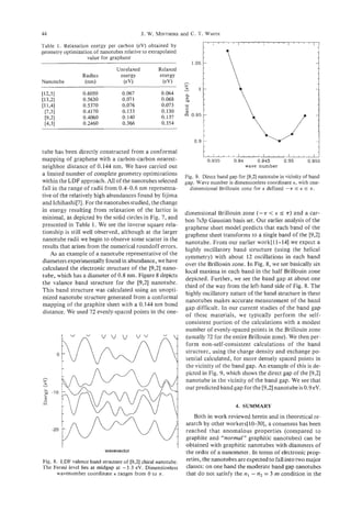
![Electronic and structural properties of carbon nanotubes 45
graphene sheet, and on the other hand the small band 4. G . G. Tibbetts, J. Crystal Growth 66, 632 (1983).
gap and truly metallic serpentine conformation nano- 5. J. S. Speck, M. Endo, and M. S. Dresselhaus, J. Crys-
tal Growth 94, 834 (1989).
tubes that do satisfy this condition. We have earlier 6. T . W. Ebbesen and P. M. Ajayan, Nature (London) 358,
demonstrated[ 10-121 for the serpentine nanotubes 220 (1992).
that, for diameters under a nanometer, we expect that 7. S. Iijima and T . Ichihashi, Nature (London) 363, 603
the density of states at the Fermi level is comparable (1993).
to metallic densities and that the nanotubes should not 8. D. S. Bethune, C. H. Klang, M. S. DeVries, G . Gorman,
R. Savoy, J. Vazquez, and R. Beyers, Nature (London)
Peierls-distort at normal temperatures. Independent 363, 605 (1993).
of helicity, we find that the larger-diameter moderate 9. M. Endo, K. Takeuchi, S. Igarashi, K. Kobori, M.
band gap members of the family of moderate band Shiraishi, and H. W. Kroto, J. Phys. Chem. SoNds 54,
gap nanotubes (nl- n2 # 3 m ) have bandgaps given 1841 (1993).
10. J. W. Mintmire, B. I. Dunlap, and C. T. White, Phys.
approximately by Eg = I V,,I ( rcc/RT) and hence do Rev. Lett. 68, 631 (1992).
not have bandgaps approaching kBT at room temper- 11. C. T. White, J. W. Mintmire, R. C. Mowrey, D. W.
ature until their diameters exceed approximately about Brenner, D. H. Robertson, J. A. Harrison, and B. I.
30 nm[lO]. Dunlap, In Buckminsferfullerenes(Edited by W. E. Bil-
We have also examined the energetics and elastic lups and M. A. Ciufolini) pp. 125-184. VCH, New York,
(1993).
properties of small-diameter graphitic nanotubes using 12. J. W. Mintmire, D. H. Robertson, B. I. Dunlap, R. C.
both first-principles and empirical potentials[W] . We Mowrey, D. W. Brenner, and C. T . White, Electrical,
find that the strain energy per carbon relative to an un- Optical, and Magnetic Properties of Organic Solid State
strained graphite sheet goes as 1/R$ (where RT is the Materials (Edited by L. Y. Chiang, A. E Garito, and
D. J. Sandman) p. 339. MRS Symposia Proceedings No.
nanotube radius) and is insensitive to other aspects of 247. Materials Research Society, Pittsburgh (1992).
the lattice structure, indicating that relationships de- 13. C. T. White, D. H. Robertson, and J. W. Mintmire,
rivable from continuum elastic theory persist well into Phys. Rev. B 47, 5485 (1993).
the small radius limit. In general, we find that the elas- 14. J. W. Mintmire, D. H. Robertson, and C. T. White, J.
tic properties are those expected by directly extrapo- Phys. Chem. Solids 54, 1835 (1993).
15. N. Hamada, S. Sawada, and A. Oshiyamu, Phys. Rev.
lating the behavior of larger graphitic fibers to a small Lett. 68, 1579 (1992).
cross-section. 96. R. Saito, M. Fujita, G. Dresselhaus, M. S. Dresselhaus,
The recent advances in synthesis of single-shell Phys. Rev. B 46, 1804 (1992). Mater. Res. SOC. Sym.
nanotubes should stimulate a wealth of new experi- Proc. 247,333 (1992); Appl. Phys. Lett. 60,2204 (1992).
47. R. Saito, G. Dresselhaus, and M. S. Dresselhaus, J.
mental and theoretical studies of these promising ma- Appl. Phys. 73, 494 (1993).
terials aimed at determining their structural, electronic, 18. H. Ajiki and T. Ando, J. Phys. Soc. Japan 62, 1255
and mechanical properties. Many questions remain to (1993). J. Phys. Soc. Japan 62, 2470 (1993).
be further investigated. How can they be termi- 19. P.-J. Lin-Chung and A. K. Rajagopal, J: Phyx C6,3697
nated[29,43] and can they be connected[30]? What are (1994). Phys. Rev. B 49, 8454 (1994).
20. X. Blase, L. X. Benedict, E. L. Shirley, and S. G . Louie,
their electrical properties? For those that are semicon- Phys. Rev. Lett. 72, 1878 (1994).
ductors, can they be successfully doped[#]? What are 21. D. J. Klein, W. A. Seitz, and T. G. Schmalz, J. Phys.
the mechanical properties of these nanotubes? How Chem. 97, 1231 (1993).
will they respond under compression and stressI23- 22. K. Harigaya, Phys. Rev. B 45, 12071 (1992).
23. D. H. Robertson, D. W. Brenner, and J. W. Mintmire,
28]? Do they have the high strengths and rigidity that Phys. Rev. B 45, 12592 (1992).
their graphitic and tubular structure implies? How are 24. A. A. Lucas, P. H. Lambin, and R. E. Smalley, J. Phys.
these nanotubes formed[43,45,46]? Can techniques be Chem. Solids 54, 581 (1993).
devised that optimize the growth and allow the extrac- 25. J.-C. Charlier and J.-P. Michenaud, Phys. Rev. Lett. 70,
tion of macroscopic amounts of selected nano- 1858 (1993).
26. G. Overney, W. Zhong, and D. Tomanek, Z . Phys. D
tubes[7,8]? These questions all deserve immediate 27, 93 (1993).
attention, and the promise of these noveI all-carbon 21. R. S. Ruoff, J. Tersoff, D. C. Lorents, S. Subramoney,
materials justify this as a major research area for the and B. Chan, Nature 364, 514 (1993).
current decade. 28. J. Tersoff and R. S . Ruoff, Phys. Rev. Lett. 73, 676
(1994).
29. M. Fujita, R. Saito, G . Dresselhaus, M. S. Dresselhaus,
Acknowledgements-This work was supported by the Office
Phys. Rev. B 45, 13834 (1992).
of Naval Research (ONR) through the Naval Research Lab-
30.. B.i. Dunlap, Phys. Rev. B 46, 1933 (1992).
oratory and directly through the ONR (Chemistry-Physics
31. J. C. Slater and G. E Koster, Phys. Rev. 94, 1498 (1954).
and Materials Divisions. We thank D. H. Robertson, D. W.
Brenner, and E. I. Dunlap for many useful discussions. 32. M. L. Elert, J. W. Mintmire, and C. T. White, J. Phys.
(Paris), Colloq. 44, C3-451 (1983).
33. M. L. Elert, C. T. White, and J. W. Mintmire, Mol.
REFERENCES Cryst. Liq. Cryst. 125, 329 (1985). C. T. White, D. H.
Robertson, and J. W. Mintmire, unpublished.
1. S. Iijima, Nature (London) 354, 56 (1991). 34. J. W. Mintmire and C . T. White, Phys. Rev. Lett. 50,
2. W. Kratschmer, L. D. Lamb, K. Fostiropoulos, and 101 (1983). Phys. Rev. B 28, 3283 (1983).
D. R. Huffman, Chem. Phys. Lett. 170, 167 (1990). Na- 35. J. W. Mintmire, In Density Functional Methods in
ture 347, 354 (1990). Chemistry (Edited by J. Labanowski and 3. Andzelm)
3. W. E. Billups and M. A. Ciufolini, eds. Buckminster- p. 125. Springer-Verlag, New York (1991).
fullerenes. VCH, New York (1993). 36. B. I. Dunlap, J. W. D. Connolly, and J. R. Sabin, J.](https://image.slidesharecdn.com/13709313-carbon-nanotubes-120928071547-phpapp01/85/13709313-carbon-nanotubes-58-320.jpg)

![CARBON NANOTUBES WITH SINGLE-LAYER WALLS
CHING-HWAKIANG,^^' WILLIAM GODDARD
A. 111: ROBERT
BEYERS,’
and DONALD BETHUNE’
S.
‘IBM Research Division, Almaden Research Center, 650 Harry Road,
San Jose, California 95120-6099, U.S.A.
’Materials and Molecular Simulation Center, Beckman Institute, Division of Chemistry and
Chemical Engineering, California Institute of Technology, Pasadena, California 91 125, U.S.A.
(Received 1 November 1994; accepted 1 February 1995)
0
Abstract-Macroscopic quantities of single-layer carbon nanotubes have recently been synthesized by co-
condensing atomic carbon and iron roup or lanthanide metal vapors in an inert gas atmosphere. The nano-
K
tubes consist solely of carbon, sp -bonded as in graphene strips rolled to form closed cylinders. The
structure of the nanotubes has been studied using high-resolution transmission electron microscopy. Iron
group catalysts, such as Co, Fe, and Ni, produce single-layer nanotubes with diameters typically between
1 and 2 nm and lengths on the order of micrometers. Groups of shorter nanotubes with similar diameters
can grow radially from the surfaces of lanthanide carbide nanoparticles that condense from the gas phase.
If the elements S, Bi, or Pb (which by themselves do not catalyze nanotube production) are used together
with Co, the yield of nanotubes is greatly increased and tubules with diameters as large as 6 nm are pro-
duced. Single-layer nanotubes are anticipated to have novel mechanical and electrical properties, includ-
ing very high tensile strength and one-dimensional conductivity. Theoretical calculations indicate that the
properties of single-layer tubes will depend sensitively on their detailed structure. Other novel structures,
including metallic crystallites encapsulated in graphitic polyhedra, are produced under the conditions that
lead to nanotube growth.
Key Words-Carbon, nanotubes, fiber, cobalt, catalysis, fullerenes, TEM.
1. INTRODUCTION Bethune et al., on the other hand, vaporized Co and
graphite under helium buffer gas, and found single-
The discovery of carbon nanotubes by Iijima in 1991[I]
created much excitement and stimulated extensive re- layer nanotubes in both the soot and in web-like ma-
terial attached to the chamber walls[3].
search into the properties of nanometer-scale cylindri-
cal carbon networks. These multilayered nanotubes
were found in the cathode tip deposits that form when 2. SYNTHESIS OF SINGLELAYER
a DC arc is sustained between the graphite electrodes CARBON NANOTUBES
of a fullerene generator. They are typically composed
of 2 to 50 concentric cylindrical shells, with outer di- In a typical experiment to produce single-layer
ameters typically a few tens of nm and lengths on the nanotubes, an electric arc is used to vaporize a hollow
order of pm. Each shell has the structure of a rolled graphite anode packed with a mixture of metal or
up graphene sheet-with the sp2 carbons forming a metal compound and graphite powder. Two families
hexagonal lattice. Theoretical studies of nanotubes of metals have been tried most extensively to date:
have predicted that they will have unusual mechani- transition metals such as Fe, Co, Ni, and Cu, and lan-
cal, electrical, and magnetic properties of fundamen- thanides, notably Gd, Nd, La, and Y.While these two
tal scientific interest and possibly of technological metal groups both catalyze the formation of single-
importance. Potential applications for them as one- layer nanotubes, the results differ in significant ways.
dimensional conductors, reinforcing fibers in super- The iron group metals have been found to produce
strong carbon composite materials, and sorption high yields of single-layer nanotubes in the gas phase,
material for gases such as hydrogen have been sug- with length-to-diameter ratios as high as several thou-
gested. Much of the theoretical work has focussed on sand[2-11]. To date, no association between the nano-
single-layer carbon tubules as model systems. Meth- tubes and metal-containing particles has been clearly
ods to experimentally synthesize single-layer nanotubes demonstrated. In contrast, the tubes formed with lan-
were first discovered in 1993, when two groups inde- thanide catalysts, such as Gd, Nd, and Y, are shorter
pendently found ways to produce them in macroscopic and grow radially from the surface of 10-100 nm di-
quantities[2,3]. These methods both involved co- ameter particles of metal carbide[8,10,12-15], giving
vaporizing carbon and a transition metal catalyst and rise to what have been dubbed “sea urchin” parti-
produced single-layer nanotubes approximately 1 nm cles[121. These particles are generally found in the soot
in diameter and up to several microns long. In one case, deposited on the chamber walls.
Iijima and Ichihashi produced single-layer nanotubes Some other results fall in between or outside these
by vaporizing graphite and Fe in an Ar/CH4 atmo- main groups. In the case of nickel, in addition to long,
sphere. The tubes were found in the deposited soot[2]. straight nanotubes in the soot, shorter single-layer
47](https://image.slidesharecdn.com/13709313-carbon-nanotubes-120928071547-phpapp01/85/13709313-carbon-nanotubes-60-320.jpg)
![48 C.-H. KIANGet al.
tubes growing radially (urchin style) for fcc-Ni or anode[4,5]. These parameters are found to change the
NiC3 particles in the rubbery collar that forms around yield of nanotubes, but not the tube characteristics
the cathode have also been found[16,17]. Second de- such as the diameter distribution. In contrast, the pres-
spite the fact that copper reportedly does not catalyze ence of certain additional elements, although they do
single-layer tube growth in the gas phase[1I], Lin et ai. not catalyze nanotube growth when used alone, can
found that numerous short, single-layer tube struc- greatly modify both the amount of nanotube produc-
tures form on the cathode tip when a Cu-containing tion and the characteristics of the nanotubes. For ex-
anode is used[lS]. Finally, the growth of single-layer ample, sulfur[5], bismuth, and lead[6] all increase the
tubules on a graphite substrate by pyrolyzing a hydro- yield and produce single-layer nanotubes with diam-
gedbenzene mixture in a gas-phase flow-reactor at eters as large as 6 nm, much larger than those formed
1000°C was recently reported[l9]. That experimental with Co catalyst alone. Sulfur also appears to promote
result is unique among those described here, in that the encapsulation of Co-containing crystallites into
no metal atoms are involved. An overview of some of graphitic polyhedra. Lambert et al. recently reported
the experimental results on single-layer nanotubes is that a platinum/cobalt 1: 1 mixture also significantly
presented in Table 1. increased the yield of nanotubes[ 111, even though Pt
In the arc-production of nanotubes, experiments to alone also has not produced nanotubes[9,11].
date have been carried out in generally similar fash- Different product morphologies have been found
ion. An arc is typically run with a supply voltage of in different regions of the arc-reactor chamber. On
20-30 V and a DC current of 50-200 A (depending on the cold walls, a primary soot is deposited. In normal
the electrode diameters, which range from 5-20 mm). fullerene production, this soot has a crumbly, floccu-
Usually He buffer gas is used, at a pressure in the lent character. However, under conditions that lead
range 50-600 Torr and flowing at 0-15 ml/min. The to abundant nanotube growth, the density of tubes in
anode is hollowed out and packed with a mixture of this soot can be high enough to give it a rubbery char-
a metal and powdered graphite. In addition to pure acter, allowing it to be peeled off the chamber wall in
iron group metals, mixtures of these rnetals[7,S,lO] sheets. This rubbery character may be caused by either
and metal compounds (oxides, carbides, and sulfides) chemical or physical cross-linking between the nano-
[5] have been successfully used as source materials for tubes and the soot. We note that fullerenes in amounts
the catalytic metals in nanotube synthesis. The ratio comparable to those obtained without a metal present
of metal to graphite is set to achieve the desired metal can be extracted from the rubbery soots using the nor-
concentration, typically a few atomic percent. mal solvents. Second, a hard slag is deposited on the
Parameter studies have shown that single-layer cathode tip. This cathode tip contains high densities of
nanotubes can be produced by the arc method under multilayer nanotubes and polyhedral particles[20,21].
a wide range of conditions, with large variations in The fact that the transition-metal-catalyzed single-
variables such as the buffer gas pressure (100-500 layer nanotubes are distributed throughout the soot
Torr), gas flow rate, and metal concentration in the and rarely in the slag deposit leads to the conclusion
Table 1. Results on single-layer nanotubes*
Fe 0.7-1.6 0.80, 1.05 Fe,C
Fe 0.6-1.3 0.7-0.8 -
co 0.9-2.4 1.3, 1.5 fcc-co
co 1-2 1.2-1.3 Co wrapped with graphene layers
co 0.6-1.8 -
Ni 1.2-1.5 - fcc-Ni in polyhedra in cathode deposit
Ni 0.6-1.3 0.7-0.8
Fe+Ni 0.9-3.1 1.7
Fe+Ni >0.6 1.3-1.8
Co+Ni 10.6 1.2-1.3 -
co+s 1.0-6.0 1.3, 1.5 Co(C) in polyhedra and fcc-Co
Co+Bi 0.8-5 1.2, 1.5
Co+Pb 0.7-4 - -
Co+Pt =2 CoPt
Y 1.1-1.7 YC2 in polyhedra
cu 1-4 Cu in polyhedra t181 g
no metal >2 graphite substrate 1191 h
*Unless specified, samples were from soot deposited on the chamber wall and the buffer gas was helium. Elements are
those incorporated in the graphite anode, D is the nanotube diameter range, D is the most abundant nanotube diame-
,
ter, and Crystallites refers to metal-containing particles generated by the arc process and found in the soot.
‘Statistics from 60 tubes; bfrom 40 tubes; ‘from over 100 tubes; dfrom 70 tubes; ‘from over 300 tubes; ‘Nanotubes grew
radially out of YC, crystals, 15-100 nm long; gNanotubes found in the cathode deposit, 3-40 nm long; hNanotubes formed
by C6Hs pyrolysis on graphite substrate.](https://image.slidesharecdn.com/13709313-carbon-nanotubes-120928071547-phpapp01/85/13709313-carbon-nanotubes-61-320.jpg)
![Carbon nanotubes with single-layer walls 49
that, in that case, the nanotubes form in the gas phase. pulling the tubules out of the soot mass has aligned
Third, a soft rubbery blanket or collar builds up them to a striking degree. A high resolution TEM
around the cathode when iron group metals are used. (HRTEM) image of a group of nanotubes (Fig. 2c)
This material has been found to contain graphitic poly- demonstrates their tendency to aggregate into bundles.
hedral particles, metals or metal carbides encapsulated The aggregation process is presumably driven by van
in polyhedral particles, string of beads structures[8,16], der Waals attraction, which has been shown experi-
and single-layer nanotubes[4,8,16]. Finally, with some mentally to give rise to significant forces between ad-
catalysts, notably Co, mixtures of Co with Fe, Ni, Pt, jacent multilayer nanotubes[22], and is predicted to
S, Bi, and Pb, and Fe/Ni mixtures, web-like materi- give rise to ordering of bundled single-layer nanotubes
als form inside the chamber when the arc is running into crystalline arrays[23]. A micrograph showing a
[3,6,8,111. bundle of Ni-catalyzed nanotubes end-on lends some
Figure 1 is a scanning electron micrograph (SEM) support to this idea[ 171.
of a sample of the web-like material obtained by va- The metals Y and Gd have been found to facilitate
porizing Co and C under 400 Torr He[3]. The threads the growth of urchin particles - consisting of bundles
and bundles of carbon nanotubes, often partly clad of relatively short single-layer nanotubes rooted on
with a layer of non-crystalline carbon and fullerenes. and extending radially outward from metal carbide
The threads connect rounded particles with typical di- particles, such as Gd,C,[12,15] and YC2[8,14,17].
ameters of a few tens of nanometers. Figure 2a is a These tubules have diameters of 1 to 2 nm, similar to
transmission electron microscope (TEM) image of the the longer tubules produced by the iron group metals,
nanotube bundles. The sample was prepared by son- but have lengths of only 10 to 100 nm. These struc-
icating some soot in ethanol for a few minutes and tures have been found in the primary soot, suggesting
placing a drop of the liquid on a holey-carbon-coated that they form in the gas phase. However, the simi-
copper TEM grid. Shown in the micrograph is a re- lar structures reported for the case of Ni were found
gion where a gap in the holey-carbon film was formed in the rubbery blanket surrounding the cathode[ 16,171.
after the soot was put on the grid. Bundled and indi- In that case, the nanotubes radiated from metal par-
vidual nanotubes bridge the = 0.25 pm gap. The soot ticles that were identified by electron diffraction to be
particles themselves consist of non-crystalline carbon crystalline fcc-Ni or Ni3C. The Ni-containing parti-
containing dark spots that have been identified by En- cles were typically encased in several graphitic carbon
ergy Dispersive X-ray Spectroscopy (EDS) and electron layers, and the free ends of the short, radial single-
diffraction to befcc-Co particles[3]. Figure 2b, taken walled tubes were generally observed to be capped.
at higher magnification, shows a region where a high In the experiment of Lin et ai., Cu was used in the
density of tubes span a gap in the soot. The process of anode and single-layer nanotubes formed in the cen-
ter region of the cathode deposit[l8]. These tubes had
lengths of a few tens of nanometers and diameters of
1-4 nm. Unlike tubes produced using transition met-
als or lanthanides, these nanotubes usually had irreg-
ular shapes, with diameters varying along the tube
axes. From this Lin et al. infer that the nanotube struc-
tures contain relatively high densities of pentagonal
and heptagonal defects. The tubes were not found to
be associated with Cu-containing particles. Copper
crystallites loosely wrapped in graphitic carbon were
occasionally found in the cathode deposit.
Recently, a non-arc method leading to single-layer
nanotube production was reported. Endo et al. dem-
onstrated that sections of single-layer nanotubes form
at early times when a benzene/hydrogen mixture is
pyrolyzed at 1000°C over a graphite substrate[l9]. In
this work, primary nanotubes quite similar to arc-
produced carbon nanotubes form, in some cases with
only single-layer graphene walls and diameters as small
as 2-3 nm. At later times, these primary pyrolytic car-
bon nanotubes (or PCNTs) accrete additional amor-
phous pyrolytic carbon and grow into fibers with pm
diameters and cm lengths. High-temperature anneal-
ing can then be used to increase the crystallinity of the
fibers. The process to make PCNTs is distinguished
from that used to make vapor-grown carbon fibers
(VCGCF)[24,25] by the fact that VGCF is produced
Fig. 1. Scanning electron micrograph of the soot taken from by thermally decomposing hydrocarbon vapor in the
the chamber wall; the threads are nanotube bundles. presence of a transition metal catalyst.](https://image.slidesharecdn.com/13709313-carbon-nanotubes-120928071547-phpapp01/85/13709313-carbon-nanotubes-62-320.jpg)
![50 C.-H. KIANG et af.
Fig. 2a. Bundles and individual single-layer carbon nanotubes bridge across a gap in a carbon film.
3. STRUCTURE OF SINGLE-LAYER On the molecular scale, single-layer carbon nano-
CARBONNANOTUBES tubes can be viewed either as one-dimensional crystals
or as all-carbon semi-flexible polymers. Alternatively,
The structure of an ideal straight, infinitely long, one can think of capped nanotubes as extended ful-
single-layer nanotube can be specified by only two lerenes[27]. For example, one can take a Csomolecule
parameters: its diameter, D,and its helicity angle, and add a belt of carbon to form a C,o. By repeating
a, which take on discrete values with small incre- the process, one can make a long tubule of 0.7 nm
ments[2,26]. These atomic scale structural parameters diameter with zero helicity[26]. Likewise, joining belts
can in principle be determined from selected area dif- of 75 edge-sharing benzene rings generates a nanotube
fraction patterns taken from a single tubule. Although of about 6 nm diameter. Nanotubes typically have di-
for multilayer tubes numerous electron diffraction ameters smaller than multilayer tubes. TEM micro-
studies confirming their graphitic structure have been graphs show that single-layer tubules with diameters
published, the very weak scattering from nm diameter smaller than 2 nm are quite flexible, and often are seen
single-layer tubes and their susceptibilityto damage by to be bent, as in Fig. 3a. Bends with radii of curvature
a 100-200 keV electron beam make it very difficult to as small as ten nm can be observed.
make such measurements. Iijima was able to show by Tubes with diameters larger than 2 nm usually ex-
diffraction that a single-layer tube indeed had a cylin- hibit defects, kinks, and twists. This is illustrated in
drical graphene sheet structure[2]. Saito reported a the TEM image of several relatively large nanotubes
similar conclusion based on diffraction from a bun- shown in Fig. 3b. The diameter of the tubes seems to
dle of several single-layer tubes[l7]. vary slightly along the tube axis due to radial defor-](https://image.slidesharecdn.com/13709313-carbon-nanotubes-120928071547-phpapp01/85/13709313-carbon-nanotubes-63-320.jpg)
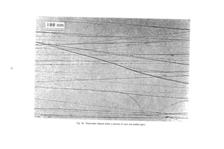
![52 C.-H. KIANG et al.
Fig. 2c. Aggregated single-layer nanotubes from soot produced by co-vaporizing Co and Bi.
mation. Classical mechanical calculations show that [38,42,43] of single-layer nanotubes, very little char-
the tubes with diameters greater than 2 nm will deform acterization beyond TEM microscopy and diffraction
radially when packed into a crystal[23], as indicated has been possible to date, due to the difficulty in sep-
by TEM images presented by Ruoff et al.[22]. The arating them from the myriad of other carbon struc-
stability of nanotubes is predicted to be lowered by tures and metal particles produced by the relatively
the defects[28]. This may account for the observation primitive synthetic methods so far employed. Recently,
that smaller tubes often appear to be more perfect be- it was reported that the Raman spectrum of a sample
cause, with their higher degree of intrinsic strain, containing Co-catalyzed nanotubes showed striking
smaller tubes may not survive if defective. The most features that could be correlated with theoretical pre-
likely defects involve the occurrence of 5- and 7-fold dictions of the vibrational properties of single-layer
rings. These defects have discrete, specific effects on tubules[44]. Kuzuo et al. [45] were able to use trans-
the tube morphology, and can give changes in tube di- mission electron energy loss spectroscopy to study the
ameter, bends at specific angles, or tube closure, for electronic structure of a bundle of single-layer nano-
example[29,30,3 11. By deliberately placing such de- tubes selected by focusing the electron beam to a 100-
fects in specific locations, it would be possible in prin- nm diameter circular area. Features of the spectra
ciple to create various branches and joints, and thus obtained were shifted and broadened compared to the
to connect nanotubes together into elaborate 3-D corresponding features for graphite and multilayer
networks[32,33]. nanotubes. These changes were tentatively interpreted
Despite a wealth of theoretical work on the elec- to be effects of the strong curvature of the nanotube
tronic structure [26,34-411, and vibrational properties wall.](https://image.slidesharecdn.com/13709313-carbon-nanotubes-120928071547-phpapp01/85/13709313-carbon-nanotubes-65-320.jpg)
![Carbon nanotubes with single-layer walls 53
P
Fig. 3a. Small-diameter tubes are often bent and curled.
4. THE METAL PARTICLES ical and are wrapped with layers of graphene sheet with
no gaps. The low-temperature phases, a-Fe and a-hcp
The encapsulated ferromagnetic particles produced Co, form abundantly, whereas the high-temperature
by this process may eventually be of technological in- phases, P-Fe and 0-fcc Co, comprise less than 10% of
terest, for example, in the field of magnetic storage the metal particle. In contrast, the metal particles found
media. Some work characterizing the magnetic prop- in the soot on the chamber wall contain mostly high-
erties of the encapsulated Co particles produced by temperature phases, such as Fe,C[2], fcc-C0[3,47], and
arc co-evaporation with carbon has been recently re- fcc-Ni[l6], and not all of the particles are wrapped in
ported[46]. The phase and composition of the metal- graphitic layers. These findings show that as the par-
containing particles may also provide information on ticles move away from the arc their temperature is
the growth conditions in the reactor. The temporal and rapidly quenched. The relatively fast time scale for re-
spatial profiles of temperature, metal and carbon den- action that this implies may be crucial for the growth
sities, and reaction rates all affect the growth of both of single-layer carbon nanotubes and, in particular, it
these particles and the nanotubes. The composition of may preclude the growth of additional layers of car-
the metal-containing particles in the soot deposited at bon on the single-layer tubules.
regions away from the electrode is not the same as for The presence of sulfur is found to enhance the for-
those found in the cathode deposit. For iron group mation of graphitic carbon shells around cobalt-
metals, pure metallic particle as well as cementite phase containing particles, so that cobalt or cobalt carbide
(Fe,C, Co3C, and Ni,C) exist in the outer surface of particles encapsulated in graphitic polyhedra are found
the cathode deposit[ 161. These particles appear spher- throughout the soot along with the single-layer nano-](https://image.slidesharecdn.com/13709313-carbon-nanotubes-120928071547-phpapp01/85/13709313-carbon-nanotubes-66-320.jpg)
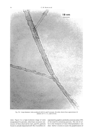
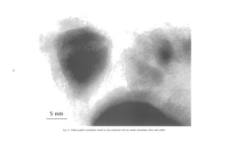
![56 C.-H. KIANGet ai.
vapor-grown carbon fibers, but the detailed process ameter nanotubes produced with Fe, Co, and Co/S,
is not yet understood[51]. adapted from earlier reports[2,5]. In comparing the di-
ameter distributions produced using Co and Co/S,
there is striking correlation of both the overall max-
5. GROWTH OF SINGLE-LAYER
ima and even the fine structures exhibited by the dis-
CARBON NANOTUBES
tributions (Figs. 5b and 5c, respectively). For the cases
There remains a major puzzle as to what controls where large diameter tubes (> 3 nm) are produced by
the growth of these nanotubes, and how it precludes adding S, Pb, or Bi to the cobalt, the tubes are still
the formation of additional layers. The reaction con- exclusively single-layered. We observed only one
ditions in the electric arc environment used for nano- double-layer nanotube out of over a thousand tubes
tube production to date are not ideal for mechanistic observed. This suggests that nucleation of additional
studies, since the plasma composition near the arc is layers must be strongly inhibited. The stability of
very complex and inhomogeneous, making individual nanotubes as a function of their diameter has been in-
variables impossible to isolate. So far, we can only ex- vestigated theoretically via classical mechanical calcu-
amine the product composition to extract clues about lations[52,53]. The tube energies vary smoothly with
the growth mechanism. One feature that can be ana- diameter, with larger diameter tubes more stable than
lyzed is the diameter distribution of single-layer car- smaller ones. The narrow diameter distributions and
bon nanotubes formed. Table 1 summarizes the data occurrence of only single-layer tubes both point to the
available. This should be considered to be only a qual- importance of growth kinetics rather than energetic
itative description, given the non-systematic sampling considerations in the nanotube formation process.
procedures, statistical uncertainties, and wide varia- S, Pb, and Bi affect the Co-catalyzed production
tions in the growth conditions used in various labo- of single-layer nanotubes by greatly increasing the
ratories. The nanotube diameters were obtained from yield and the maximum size of the nanotubes. The for-
high-resolution TEM images. At a gross level, the mation of web-like material in the chamber is very dra-
most interesting aspect of the accumulated data is the matically enhanced. As noted above, these elements
consistency of the production of 1-2 nm diameter do not produce nanotubes without a transition metal
tubes by the various metals and combinations of met- present. How these effects arise and whether they in-
als. The exceptional cases are the combinations of Co volve a common mechanism is not known. In the pro-
with S, Pb, or Bi, which produce considerably large duction of VGCF, sulfur was found to be an effective
tubes. Even in those cases, the main peak in the dis- scavenger for removing blocking groups at graphite
tribution occurs between 1 and 2 nm. Figure 5 presents basal edges[51]. The added elements may assist the
detailed histograms of the abundance of different di- transport of carbon species crucial for the growth of
nanotubes in the vicinity of the arc. Or they could act
as co-catalysts interacting with Co to catalyze the re-
action, or as promoters helping to stabilize the reac-
tants, or simply as scavengers that remove blocking
groups that inhibit tube growth.
Growth models for vapor-grown carbon fibers
(VGCF) have been proposed[24,25]. Those fibers, pro-
duced by hydrocarbon decomposition at temperatures
around 12OO0C,are believed to grow from the surface
bl of a catalyst particle, with carbon deposited on the
particle by decomposition of the hydrocarbon migrat-
L
ing by diffusion through the particle, or over its sur-
face, to the site where the fiber is growing. The fiber
size is comparable to the size of the catalytic particle,
but can thicken if additional pyrolytic carbon is de-
posited onto the fiber surface. It is tempting to think
c1 that single-wall nanotubes may also grow at the sur-
faces of transition metal particles, but particles much
smaller than those typical in VGCF production. To
date however, the long single-layer nanotubes found
in the soot have not been definitely associated with
metal particles. Thus, how the metal exerts its cata-
0 1 2 3 4 5 6
lytic influence, and even what the catalytic species are,
Nanotube dlameter (nm) remain open questions. The urchin particles produced
by lanthanide or Ni catalysts do show an association
Fig. 5. Diameter distributionsof nanotubes produced via dif- between the single-layer nanotubes and catalyst par-
ferent methods: (a) Fe catalyst in an Ar/CH, atmosphere,
adapted from Ref. 2; (b) Co catalyst in He atmosphere, ticles. In this case, the particles are 10 to 100 times
adapted from Ref. 5 ; (c) Cocatalyst with sulfur, about 4 at.% larger than the tube diameters. In the case of single-
each, adapted from Ref. 5 . layer tubes produced by Cu in the cathode deposit,](https://image.slidesharecdn.com/13709313-carbon-nanotubes-120928071547-phpapp01/85/13709313-carbon-nanotubes-69-320.jpg)
![Carbon nanotubes with single-layer walls 57
growth occurs under extreme conditions of tempera- high (1600°C) temperature[ll]. The amorphous car-
ture and carbon density. The nanotubes produced also bon soot particles, however, are difficult to remove,
have very different characteristics. Therefore, we ex- and the oxidative approach used with some success to
pect that their formation mechanism will be quite dif- isolate multilayer tubes[58] seems to destroy the single-
ferent. It is possible that instead of growth occurring layer tubes. Measurement of the mechanical, optical,
at a metal particle interface, as has been proposed for electrical, and magnetic properties requires a clean
VOCF, urchin particles[& 171, and long single-walled sample to interpret the data unambiguously. Tests of
nanotubes[5], a mechanism more akin to those pro- the dependence of electrical conductivity and mechan-
posed for the growth of multilayer nanotubes on the ical strength on the tube diameter should be done, and
cathode tip in an all-carbon environment may be in- may soon be feasible with the availability of nanotubes
volved[21,26,29,54]. In that case, it has been suggested with a wide range of diameters.
that growth occurs at the free end of the nanotube, The unique properties of single-layer carbon nano-
which protrudes out into the carbon plasma. tubes will continue to inspire scientists in diverse fields
Some features of the arc process are known and are to explore their properties and possible applications.
relevant to growth models for single-layer nanotubes. Defect-free nanotubes are predicted to have very high
Earlier isotope labelling analyses of fullerene forma- tensile strength. A theoretical calculatior, of the elastic
tion shows that fullerenes formed in the arc are built constant for single-layer nanotubes[52] gives a result
up from atomic carbon[55-57]. Also, the production consistent with a simple estimate based on the c, elas-
of nanotubes does not seem to depend on whether tic constant of graphite (cI1= 1.06 TPa). Using this
metal oxide or pure metal is used in the graphite an- constant, one finds a force constant of 350 Nt/(m of
ode. These results imply that both the metal and the edge) for graphene sheet. Multiplying this value by the
carbon are completely atomized under the arc condi- circumference of a 1.3 nm diameter nanotube gives
tions, and that both the catalytic species and nano- an elastic constant of 1.45 x Nt for such a tube.
tubes must be built up from atoms or atomic ions. Macroscopically, a bundle of these tubes 25 pms in di-
This fact, together with the consistency of the diam- ameter would support a 1-kg weight at a strain of 3%.
eters of the single-layer nanotubes produced in the gas In comparison, a steel wire of that diameter would
phase by transition metal catalysts, suggests a model break under a load of about 50 gm. When nanotubes
where small catalytic particles rapidly assemble in a re- are assembled into crystalline bundles, the elastic mod-
gion of high carbon density. Single-layer tubules nu- ulus does not decrease linearly with tube diameter but,
cleate and grow very rapidly on these particles as soon rather, it remains constant for tube diameters between
as they reach a critical size, leading to the relatively 3 and 6 nm, suggesting the strength-to-weight ratio
narrow diameter distributions observed. If nucleation of the crystal increases as the tube diameter increases
of additional layers is slow, the rapid drops in temper- [23]. The anisotropy inherent in the extreme aspect
ature and carbon density as the tubes move away from ratios characteristic of these fibers is an important
the arc could turn off the growth processes before feature, particularly if they can be aligned. Ab initio
multilayers can form. calculations show that these nanotubes could be one-
dimensional electric conductors or semiconductors,
depending on their diameter and helicity[36,39,59].
6. FUTURE DIRECTIONS
Other applications of carbon nanotubes have been
Experimental research on single-layer nanotubes is proposed in areas that range widely, from physics,
still in a very early stage. Understanding the growth chemistry, and materials to biology. Examples, such
mechanism of these nanotubes remains a great chal- as hydrogen storage media, nanowire templates, scan-
lenge for scientists working in this area. Not even the ning tunneling microscopy tips, catalyst supports, seeds
nature of the catalytically active species has been es- for growing carbon fibers, batteries materials, reinforc-
tablished to date. Developing better controlled systems ing fillings in concrete, etc. provide ample motivation
than standard arc reactors will be necessary to allow for further research on this pseudo-one-dimensional
the dependence of tube growth on the various impor- form of carbon.
tant parameters to be isolated. The temperature and
the carbon and metal densities are obvious examples Acknowledgement-This research is partially supported by
of such parameters. In the arc plasma, they are highly the NSF (ASC-9217368) and by the Materials and Molecu-
lar Simulation Center. We thank J. Vazquez for help with the
coupled and extremely inhomogeneous. Knowledge of SEM imaging of nanotubes, G . Gorman and R. Savoy for
the growth mechanism will possibly allow us to opti- X-ray analysis, and M. S. de Vries for mass spectrometry.
mize the fabrication scheme and the characteristics of
the nanotubes.
A second key problem is to devise means to sepa- REFERENCES
rate the tubes from the soot and metal particles, either
chemically or mechanically. This is an essential step 1. S. Iijima, Nature 354, 56 (1991).
2. S. Iijima and T. Ichihashi, Nature 363, 603 (1993).
towards manipulation and thorough characterization 3. D. S. Bethune, C. H. Kiang, M. S. deVries, G. Gorman,
of these materials. Recently, it was reported that a sig- R. Savoy, J. Vazquez and R. Beyers, Nature 363, 605
nificant fraction of the metal particles could be re- (1993).
moved from the sample by vacuum annealing it at 4. P. M. Ajayan, J. M Lambert, P. Bernier, L. Barbedette,](https://image.slidesharecdn.com/13709313-carbon-nanotubes-120928071547-phpapp01/85/13709313-carbon-nanotubes-70-320.jpg)
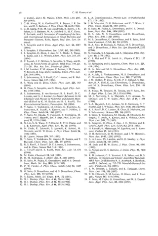
![CARBON NANOTUBES:
I. GEOMETRICAL CONSIDERATIONS
R. SETTON
Centre de Recherche sur la Matiere DivisCe, CNRS, 1 B rue de la Ftrollerie,
F 45071 OrlCans Cedex 2, France
(Received 22 August 1994; accepted 15 September 1994)
Abstrdct-The geometrical conditions pertaining to closure, helicity, and interlayer distance between suc-
cessive layers with circular cross-sections in carbon tubules (nanotubes) have been examined. Both the
intralayer length of the C-C bonds and the interlayer distance between successive layers must vary with
the radius of the layers. The division into groups of the sheets in nanotubes is found to be due to the re-
ciprocal interaction of the interlayer distance variations and of the conditions required to maintain con-
stancy of the pitch angle.
Key Words-Carbon nanotubes, pitch angIe, helix angle, interlayer distance, carbon-carbon intralayer
distance.
1. INTRODUCTION folds. The sign of 8 determines the helicity of the
scroll, counterclockwise (e> 0) or clockwise (e< 0).
Carbon tubules (or nanotubes) are a new form of
The consequence of the presence of scroll helicity
elemental carbon recently isolated from the soot ob-
in a tubule is expected to be that any increase (de-
tained during the arc-discharge synthesis of fuller-
crease) of the intralayer C-C distance G will increase
enes[11. High-resolution electron micrographs do not
(decrease) the local length of the spiral, but not nec-
favor a scroll-like helical structure, but rather concen-
essarily the mean interlayer distance, since the scroll
tric tubular shells of 2 to 50 layers, with tips closed by
can easily adapt its radius of curvature to minimize,
curved, cone-shaped, or even polygonal caps. Later
if necessary, any energetic strain due to a stress in the
work[2] has shown the possibility of obtaining single-
local bond lengths.
shell seamless nanotubes.
Recently, the structure of some helical carbon
2.2 Screw helicity
nanotubes was examined[3], and the present work is
The second type of helicity can affect both scrolls
an attempt at completing the geometrical approach to
and individual cylinders. It will be present when nei-
the structural problems encountered in the case of tu-
ther the a nor the b unit vector of the basic two-
bules with circular cross-sections. However, most of
dimensional graphite lattice of the unfolded scroll or
the conclusions in the present work are applicable to
cylinder is at an angle of 0" or at a multiple of 30"
nanotubes with polygonal cross-sections that have also
with the direction of the cylinder axis (Fig. 2). The sit-
been shown to exist.
uation is complicated by the fact that whenever screw
helicity affects a seamless cylindrical layer, any change
2. THEORY in the value of G must necessarily affect the radius r
of the cylinder. It is therefore highly likely that the in-
Leaving aside the complications engendered by the terlayer distance d between two successive cylinders is
presence of end-caps and considering, therefore, only not strictly constant in any multilayered tubule with
the cylindrical part of the tubules, one must differen- a circular cross-section, since the adverse effect of the
tiate between two types of helicity. elastic strain on the sp2 orbitals and the resulting dis-
tribution of charges- which undoubtedly affect the in-
tralayer C-C distance-progressively decreases as the
2.1 Scroll helicity
circumference and the radius of curvature of the cyl-
The presence of scroll helicity replaces a set of con-
inders increase. As justified later, one is therefore led
centric cylinders by a single sheet rolled upon itself
to introduce a parameter 6d or 6r to characterize the
(Fig. 1). Assuming that the distance between the suc-
smalI variations of r with respect to a hypothetical
cessive rolls of the scroll is constant, its cross-section
nominal value likely to be encountered even if, strictly
can be conveniently represented in polar coordinates
speaking, the variation 6G should also be taken into
by the Archimedean spiral:
account.
2.3 Symmetric non-helical tubules
and cylinders
where a is the initial radius of the innermost fold
, In the absence of both types of helicity, the non-
and d is the (constant) distance between successive helical or symmetric tubule consists-of a set of cylin-
59](https://image.slidesharecdn.com/13709313-carbon-nanotubes-120928071547-phpapp01/85/13709313-carbon-nanotubes-72-320.jpg)
![60 R. SETTON
b
Fig. 3. The two possible orientations of the hexagons in non-
helical sheets, relative to the cylinder axis (broken line);
(a) case I; (b) case I1 (see text).
Fig. 1. Approximate cross section of a tubule with scroll
helicity. The distance d between successive rolls of the spiral dius ri of the cylinder can conveniently be described
is assumed to be constant, and no is the initial radius of the
innermost fold. in terms of two orthogonal vectors[4], Pi and Qi
(Fig. 4), respectively integral multiples of the unit vec-
XI
tors x and 7 with moduli I = (3/2)G and I y I =
(&/2)G. For the ith layer, we can write:
drical sheets which, for simplicity, will be assumed to
have a common axis and a circular cross-section. The
hexagons of the unrolled cylinders all have one of their
three sets of parallel opposite sides respectively per- or, for the scalars R i , Pi, Qi,
pendicular (case I) or parallel (case 11) to the common
axis of the cylinders (Fig. 3).
The orientation of the hexagons with respect to the
tube axis of the unrolled ith cylinder as well as the ra-
where Pi, Qi are integers of identical parity, and
Ri = 27rri. (4)
The pitch angle ai characteristic of this orientation
of the hexagons is:
ai = arctan(Qi/fiPi), (5)
but one can also distinguish an apparent angle of pitch
pi between the helical rows of unbroken hexagons
and the plane perpendicular to the cylinder axis, with
Although the limits of LY are:
this angle can be limited to 30", since every ( P i ,Qi)
doublet is associated with a corresponding doublet
(Pi,-Qi), symmetric of (Pi,Qi) with respect to a =
O", yielding the same value of the radius (Fig. 5 ) and
characterizing the stereoisomer of the chiral ith cylin-
Fig. 2. A portion of an unrolled cylinder with screw helicity. drical sheet, The doublet (Pi,Qi) is also equivalent to
The broken line is parallel to the cylinder axis, and the cylin-
drical sheet has been cut along a generatrix (full line paral-
the doublet (Pi, with Pi= ( P , + Q,)/2 and Qi =
Qj),
lel t o the cylinder axis). a and b are the unit vectors of the (3P, - 2Qi)/2, with the pitch angle ai = 60" - ai.
two-dimensional carbon layer in sp2 hybridization. which also yields the same value of ri.](https://image.slidesharecdn.com/13709313-carbon-nanotubes-120928071547-phpapp01/85/13709313-carbon-nanotubes-73-320.jpg)
![Carbon nanotubes: I. Geometrical considerations 61
Fig. 4. Screw helicity: the system of (P, coordinates used to describe the orientation of the two-
Q)
dimensional sp2 carbon layer in an unrolled cylindrical sheet whose edges are shown by the slanted un-
labelled full lines. Closure of the cylinder is obtained by rolling the sheet around the direction of the cylinder
axis given by the dotted line and superimposing hexagons A and B. The slanted dashed lines correspond
to a continuous line of unbroken hexagons of the cylinder, and indicate the apparent angle of pitch 0.
l.t is therefore possible to impose the limits: hence, assuming that is practically constant and
writing d for dj,j + L ,
P Pi int[2arj/(3G/2)]
I I
2 ~ = nj,j+l (I)3G/2
d (13)
(int = integral part of) (8)
ni,j+l(I) = 10 (14)
0 IQj I i
P (9)
in which Qi = 0 and Qi = Pi correspond to cases I and
I1 respectively, and for which eqn (4) becomes:
27rri(I) = Pi3G/2 (10)
and
2Tri(11) = P,&G. (1 1)
Referring now to the symmetric tubule, the inter-
layer distance dj,j+n between two layers of radii ri and
rj;-+n
IS:
di,i+n = ri+n - Ti (12)
and, for two consecutive layers, d f , j + = 0.339 nm[5].
l
For the configuration of hexagons in case I, the in-
Fig. 5 . Screw helicity: the three vectors corresponding to
+
crease in length of the circumference of the (i 1)th ( R / Gd26, with P, = 5 , Q , = 3 and P = 4 Q, = 6 (see
= , ,
laver with reswct to the circumference of the ith layer text). The vector (Pi,-Qi) characterizes the optical isomer
must be equal to an integral and even multiple of I x I ; of (Pi,Qd.](https://image.slidesharecdn.com/13709313-carbon-nanotubes-120928071547-phpapp01/85/13709313-carbon-nanotubes-74-320.jpg)
![to better than 1 x if d = 0.339 nm and G = sible to find long series of successive cylindrical sheets
0.142 nm. This is well illustrated by the sequence with 01 = O", it is clear that one should have, for two
formed from the values rl = 0.678 nm, G = 0.142 successive cylinders with identical helicity:
nm, d = 0.339 nm, and 6r/r = 51.5%, which give
more than 30 consecutive non-helical (a! = 0") sym-
metric cylinders, with characteristics ri (nm) = 0.678 +
+
( i - 1)d and Pi = ( i 1)lO. with
2.4 Symmetrical helical cylinders + Qi",,)
(ri+l/G)' = ( 3 / 1 6 ~ ~ ) ( 3 P f + ~ (19)
with a = 30"
For the configuration of hexagons in case 11, or
ni,i+l(II)
should now be an integral and even multiple
of Iy1 or, using eqn (11), [(ri+ d)/G]' = (3/16.rr2)[3(Pi +p)' + ( Q i + q)']
= ni,i+,(II)d?G. (15)
This equality is not even approximately satisfied for in which p and q are, respectively, integral increments
small integral values of ni,i+l(II).There is, however, of Pi and Qi. For the pitch angles of the two cylinders
a possibility offered by the distance di,i+3, is, for
that to be equal, we must have:
1.02 nm, namely:
ni,i+3(11) = 2 ~ d , , ~ + ~ / & C (16)
and it can be shown that
= 26
to better than 0.2%. In other words, if a ( P i , Q i )
doublet yields a = 30", which is the pitch angle cor- In view of the remarks in Q 2.3, it is legitimate to
responding to case 11, the chances are high that this substitute the value 15 for the round bracket in the
+
angle will be repeated for the (i 3)th cylinder. A r.h.s. of eqn (22). Taking then into account the fact
good example of this is given by the series described that the maximum and minimum possible values of p
by the values rl = 0.71 nm, G = 0.1421 nm, d = are obtained when q = 0 and q = p , respectively, eqn
0.339 nm, and 6d/d = 2%, which yield CY = 30" for (22) yields:
i = 1,4, 10, 19, 22, 27, 30, 33, 36, 39, . . ., with most
differences between successive values of i either equal 8.66 ~p I10. (23)
to 3 or to a multiple of 3, and the values P, = Qi =
I&, 44, 96, 174, 200, 243, 269, 295, 321, 347,. . ., The only doublets consistent with this inequality,
which show the expected differences. with the necessity of identical parity for p and q , and
with values of r , close to 0.34 nm, are given in Table 1
2.5 Symmetric helical tubes and cylinder with (from which the doublet (10,O) can be excluded since
a different from 0" or 30" it is characteristic of a symmetrical, non-helical sheet).
Equality (4) can be rewritten as: Hence, if 6r = 0, the necessary conditionsfor two suc-
cessive helical cylindrical sheets to have strictly iden-
( r i / G ) 2 (3/l6a2)(3Pf
= + Qf). (17) tical pitch angles are:
Since the first bracket on the right-hand side is a
constant and the second is an integer, it is evident that,
for any particular i, some leeway must exist in the q : p = 7 : 9 , or 2:10, or 4:10, (25)
value of the ratio ri/G for the equality to be satisfied.
Here too, the presence of screw helicity must affect ei- since all other values would give either d < 0.334 nm
ther ri, or G , or both. In view of the fairly small vari- (which is already less than d of graphite and, there-
ations of G allowed if the hybridization of the C atoms
is to remain sp', and since the deformation of the C
orbitals decreases as the radius of the cylindrical sheets Table 1. ( p , q ) increments for obtaining identical successive
increases, the distance between successive cylinders pitch angles
must decrease and probably tend towards a value char-
acteristic of turbostratic graphite. Interlayer Pitch
(P,
4) distance d (nm) angle CY'
The second problem associated with helical sym-
metric cylindrical sheets addresses the possibility of (9,7) 0.334 24.2
finding the same helix angle or pitch in two neigh- (10,O) 0.339 0
bouring sheets. Apart from cases similar to the one (103 0.341 6.6
(10~4) 0.348 13.0
described above (case I, section 2.3) in which it is pos-](https://image.slidesharecdn.com/13709313-carbon-nanotubes-120928071547-phpapp01/85/13709313-carbon-nanotubes-75-320.jpg)
![Carbon nanotubes: I. Geometrical considerations 63
fore, highly unlikely) or d > 0.348 nm (Le., at least 4% Table 3. Computed characteristics of a 28-sheet tubule show-
above the value of graphite and also unlikely). If both ing the division into groups of sheets
conditions are met, the pitch angle is 24.18",or 6.59", i (pi,Qi) ri (nm) cyo
or 13.00". If only condition (25) above is operative,
the successive values of a will be nearly but not strictly 1 (14~0) 0.475 0
equai, and will be different from these three values. 2 (24,O) 0.814 0
Two examples illustrate these points: 3 (34,2) 1.153 1.94
4 (44,4) 1.494 3 .oo
(a) the unbroken series of 21 cylinders with a = 6.59", 5 (54,6) 1.834 3.67
r, = 0.6825 nm, G = 0.142 nm, d = 0.341 nm, 6d/d = 6 (64,8) 2.175 4.13
&1.5%, with Qi:Pi2:10, PI = 20, Pz, 220, and
= = 7 (74,101 2.516 4.46
q : p = 2:10 in all cases; 8 (84,121 2.857 4.72
9 (94,12) 3.195 4.22
(b) the five successive cylindrical sheets with r, = 10 (104~4) 3.566 4.44
10.22nm, G =0.142 nm, d =0.34 nm, 6d/d = f I S % , 11 (1 14,16) 3.877 4.63
and the characteristics shown in Table 2. A "single- 12 (123,31) 4.214 8.28
helix angle of about 3"" was observed in the selected 13 (133,33) 4.555 8.15
area electron diffraction pattern of a four-sheet sym- 14 (143,35) 4.896 8.04
metric helical tube[3], but the small variations of a 1s (1S3,37) 5.237 7.95
16 (163,39) 5.578 7.87
shown in Table 2 would obviously not have been vis-
ible in the diffractogram shown in the reference. 17 (171,61) 5.919 11.64
18 (18 1,63) 6.259 11.36
19 (191,65) 6.599 11.12
2.6 Sheet groups 20 (202,56) 6.935 9.09
It has also been stated[3] that "the helix angle (of 21 (212,SS) 7.276 8.98
a multiple-sheet helical tube) changes about every three 22 (222,60) 7.617 8.87
23 (232,62) 7.958 8.77
to five sheets" so that the gross structure of the tube is
constituted by successive groups of cylindrical sheets, 24 (239,9 1) 8.296 12.40
25 (249,93) 8.635 12.17
with the helix angles increasing by a constant value 26 (259,95) 8.975 11.96
from each group to the next. In light of the arguments 27 (269,97) 9.315 11.76
developed in the preceding paragraphs, and except for 28 (279,99) 9.655 11.56
the specific cases a = O", 6.59", 13.00", 24.18", the
pitch angle of the sheets within a group is more likely
to be nearly constant rather than strictly constant. This
is illustrated by the values in Table 3 showing the char- ues between groups 2 and 3 , and 5 and 6, the suc-
acteristics of the 28 sheets in a tube whose inner and cessive values of ( a ) increase by a nearly constant
outer radii are, respectively, equal to 0.475 and 9.66 amount, namely, about 3 to 4". The question then
nm, calculated on the basis of rl = 0.476 nm, d = arises as to the reason causing the modification of Q!
0.34 nm, G = 0.142 nm, 6d/d = +0.8%. Since a is not between two successive groups, such as the one occur-
strictly constant within each group, it is more appro- ring between i = 11 and i = 12. If (P12,Q12)had been
priate to consider a mean value ( a ) of the pitch an- (124,18) instead of (123,31), r I 2 would have been
gle for each group, as shown in Table 4. Only in the 4.218 nm with a = 4.78" (Le., within 6d/d = +1.0%
first group of sheets (i = 1 to 2) is a truly constant instead of kO.8% imposed for the values in Table 3).
( a = 0"). For all the other groups, the increments Hence, during the actual synthesis of the tube, the end
( p 9q ) of the (Pi, doublets are constant and equal
Q,) of each group must be determined by the tolerance in
to (10,2). In fact, it is because these increments are the G values accepted by the spz orbitals compatible
identical that the group pitch angles are nearly con- with the need to close the cylindrical sheet.
stant when the values of Piand Qiare sufficiently Although the physical growth mechanism of the cy-
Iarge, which is not yet the case in the second group. lindrical sheets is not yet fully known, the fact that
The above series also illustrates an experimentally
established fact[3]: Except for the change of mean vd-
Table 4. Group characteristics of the 28-sheet nanotube
described in Table 3
Table 2. Computed characteristics of a five-sheet symmet-
ric tubule with a nearly constant pitch angle Grow Range of i P, 4 (a">
I ri (nm) (Pi,
Qi) (Yo 1 1 to 2 10,o 0
2 3 to 8 10,2 3.65
1 10.22 (301,29) 3.18 3 9 to 1 1 10,2 4.43
2 10.56 (31 1,31) 3.29 4 12 to 16 10,2 8.06
3 10.90 (321,31) 3.19 5 17 to 19 10,2 11.37
4 11.24 (33 1,33) 3.29 6 20 to 23 10,2 8.93
5 11.58 (341,33) 3.20 I 24 to 28 10,2 11.97](https://image.slidesharecdn.com/13709313-carbon-nanotubes-120928071547-phpapp01/85/13709313-carbon-nanotubes-76-320.jpg)
![64 R. SETTON
successive sheets have nearly constant helicity suggests 2.8 Influence of the innermost cylinder
the following mechanism: once the ith (topmost) sheet If the template effect of Endo and Kroto[9] does
is formed, C, species in the gas phase (n = 3,1,2. . . , indeed exist and the growth of the tubule occurs out-
in order of decreasing abundance[6]) condense onto wards, a knowledge of the Characteristics of the inner-
the outer surface of the tube, probably at a distance most tube is then of paramount importance in any
slightly larger than 0.34 nm[7], in registry with the un- attempt at modelizing the structure of a symmetric
derlying substrate and in sp2 hybridization, since this nanotube[111. By reversing eqn (17), possible values
configuration is the one that best minimizes the energy for P1and Q , can be obtained from
of the system[8]. The ith sheet thus constitutes the
template for the construction of the ( i + 1)th sheet[9], 3P; + (212 = (16a2/3) [ ( r l / G ) 2 W r ] ,
* (26)
and the helicity of the as-yet-unclosed cylinder during
its formation is the same as that of the underlying sub- and the inequalities (8) and (9), provided rl has been
strate. This process continues until the C atoms on ei- determined (say, by HRTEM -high resolution trans-
ther side of the cut form the C-C bonds that close mission electron microscopy), and G is arbitrarily
the cylinder. If the geometric characteristics of these fixed, say, at G = 0.142 nm. Although the task may
bonds are too different from 120" and G = 0.142 nm, become formidable if r1 and/or 6r/r are large, the
the pitch angle w l change to the immediately higher
il number of possibilities is strictly limited, especially
or lower value, thus ensuring closure. Once the cylin- since selected area electron diffraction (SAED) can
der is closed, and even if closure only involved a single provide narrower limits by giving a first approxima-
row of hexagons, the following rows of the cylindri- tion of the pitch angle[3].
cal sheet will necessarily have the same pitch angle, at
least as long as the sheet is growing over an existing
3. CONCLUSION
substrate.
It is clear that a large number of parameters influ-
ence the formation of the sheets in a tubule and that
2.7 Smallest inner tube diameter
their relative importance is still unknown, as is also the
Liu and Cowley[3] have reported the observation
of innermost cylinders with diameters as small as 0.7 cause of the occurrence of the defects responsible for
or 1.3 nm. The first value is only slightly larger than the eventual polygonization of the sheets. Although
0.68 nm, the well known diameter of the Cs0 mol-
the model presented here highlights the necessity of in-
ecule[lO], while the second is in fair agreement with cluding, as one of the parameters, the uncertainty
6r
or 6d on the separation of successive cylindrical sheets,
1.36 nm, the calculated diameter Cm. As shown in
Table 5 , there are 5 (PI, doublets which, with G =
Q1)
it is impossibIe to predict with absolute certainty the
0.142 nm, give rl = 0.35 nm +3%, and 14 (P1,Q1)
final characteristics of any of these sheets, symmetric
doublets (not all are given in Table 4) for the larger or not, on the basis of the characteristics of thepre-
of the two values within k5%. It is interesting to find vious one. Nevertheless, a number of features of their
structure, such as the presence or absence of helicity,
that there is, in both cases, the possibility of forming
and the presence of groups of sheets with nearly the
a non-helical cylindrical sheet with or = Oo, namely
( P , , Q , ) = (10,0), rl = 0.339 nm, and (Pl,QI)= same angle of pitch, can be explained and quantified.
(20,0), rl = 0.678 nm, with the first row of C atoms
corresponding to one of the equatorial cuts of C60or REFERENCES
of C240;but ignorance of the actual mechanism of
formation of the first cylindrical sheet forbids an ob- 1. S. Iijima, Nature 354, 56 (1991).
2. X. Lin, X. K. Wang, V. P. Dravid, R. P. H. Chang, and
jective choice among the various possibilities. J. B. Ketterson, Appl. Phys. Letters 64, 181 (1994).
3. M. Liu and J. M. Cowley, Carbon 32, 393 (1994).
4. A. Setton and R. Setton, Synth. Met. 4, 59 (1981).
5 . T. W. Ebbessen and P. M. Ajayan, Nature 358, 220
(1992).
6 . D. R. Stull and G . C. Sinke, Thermodynamicproperties
Table 5 . Some possible characteristics of symmetric sheets of the elements (No. 18, Advances in Chemistry Se-
with the smallest observed radii ries), pp. 66-69. American Chemical Society, Washing-
ton (1956).
7. L. A. Girifalco and R. A. Lad, J. Chem. Phys. 25,693
(1956).
0.339 0 8. J.-C. Charlier and J.-P. Michenaud, Phys. Rev.Lett. 70,
0.341 6.59 1858 (1993).
0.348 13.00 9. M. Endo and H. W. Kroto, J. Phys. Chem. 96, 6941
0.352 30 (1992).
0.359 19.11 10. P. A . Heiney, J. E. Fischer, A. R. McGhie, W. J.
0.626 30 Romanow, A. M. Denenstein, J. P. McCauley, Jr.,
0.644 1.74 A. P. Smith 111, and D. E. Cox, Phys. Rev.Lett. 66,291
0.665 30 (199 1).
0.678 0 11. V. A. Drits and C. Tchoubar, X-Ray diffraction by
0.679 3.30 disordered lamellar structures. Springer-Verlag, Berlin
(1 990).](https://image.slidesharecdn.com/13709313-carbon-nanotubes-120928071547-phpapp01/85/13709313-carbon-nanotubes-77-320.jpg)
![SCANNING TUNNELING MICROSCOPY OF CARBON
NANOTUBES AND NANOCONES
KLAUSSATTLER
University of Hawaii, Department of Physics and Astronomy, 2505 Correa Road,
Honolulu, HI 96822, U.S.A.
(Received 18 July 1994; accepted 10 February 1995)
Abstract-Tubular and conical carbon shell structures can be synthesized in the vapor phase. Very hot car-
bon vapor, after being deposited onto highly oriented pyrolytic graphite (HOPG), forms a variety of nano-
structures, in particular single-shell tubes, multishell tubes, bundles of tubes, and cones. The structures
were analyzed by scanning tunneling microscopy (STM) in UHV. Atomic resolution images show directly
the surface atomic structures of the tubes and their helicities. A growth pathway is proposed for fuiler-
enes, tubes, and cones.
Hey Words-Carbon nanotubes, fullerenes, STM, fibers, nanostructures, vapor growth.
1. INTRODUCTION yielding quite realistic three-dimensional images from
tube terminations. Also, besides a difference in rnor-
Hollow carbon nanostructures are exciting new sys- phology, open and closed ends show a difference in
tems for research and for the design of potential nano- electronic structure. Open ends appear with ‘highlighted’
electronic devices. Their atomic structures are closely edges in STM images, which is due to an enhanced
related to their oute: shapes and are described by hex- dangling bond electron state density. Closed ends do
agonal/penitagonal network configurations. The sur- not have such highlighted edges.
faces of such structures are atomically smooth and The growth pathway of various fullerene- and
perfect. The most prominent of these objects are ful- graphene-type nano-objects may be related. They are
lerenes and nanotubes[l]. Other such novel structures synthesized in the vapor phase and often appear simul-
are carbon onions[2] and nanocones[3]. taneously on the same sample. A common growth
Various techniques have been used to image nano- mechanism with similar nucleation seeds may, there-
tubes: scanning electron microscopy (SEM)[ 11, scan- fore, lead to these different structures.
ning tunneling microscopy (STM)[4-71, and atomic
force microscopy (AFM)[S]. Scanning probe micro-
2. EXPERIMENTAL
scopes are proximity probes. They can provide three-
dimensional topographic images and, in addition, can Graphite was used as substrate for the deposition
give the atomic structure of the surface net. They can of carbon vapor. Prior to the tube and cone studies,
also be used to measure the electronic (STM) and elas- this substrate was studied by us carefully by STM be-
tic (AFMJ properties of small structures. STM is re- cause it may exhibit anomalous behavior with unusual
stricted to electrically conducting objects, but AFM periodic surface structures[9,10]. In particular, the
does not have this constraint. cluster-substrate interaction was investigated[l 11. At
STM and AFM images give directly the three- low submonolayer coverages, small clusters and is-
dimensional morphology of tubes and are consistent lands are observed. These tend to have linear struc-
with the structures inferred from SEM. In addition, tures[l2]. Much higher coverages are required for the
atomically resolved STM images make direct helicity synthesis of nanotubes and nanocones. In addition, the
determinations possible[4]. They give information carbon vapor has to be very hot, typically >3O0O0C.
about the nature of stacking of concentric carbon lay- We note that the production of nanotubes by arc dis-
ers within the nanotubes via modifications of their sur- charge occurs also at an intense heat (of the plasma
face density of states. STM is sensitive to such small in the arc) of >30OO0C.
lateral local density of states variations. Contours The graphite (grade-A HOPG) was freshly cleaved
taken from the ends of the tubes show that some of in UHV and carefully examined by STM before the
them are open and others are closed. Many images in- deposition. The HOPC surface was determined to be
dicate that the closed tubes have hemispherical caps. atomically flat and defect-free over micrometer dimen-
Such terminations can be modeled by fullerene hemi- sions. Any defect or adatom would have easily been
spheres with 5 / 6 networks. detected. The graphite was cooled to -30°C during
ICis not easy to determine detailed properties of the evaporation. The carbon vapor was produced by re-
tube terminations using STM or AFM. These micro- sistively heating a 99.99% purity carbon foil (0.5 mrri
scopes cannot image undercut surfaces and the tip thick) in UHV (base pressure 2 x lo-’ Torr). The de-
shape is convoluted with the cap shape of the nano- position rate of 0.5 A/s was controlled by a quartz
tube. However, the tips may have very sharp edges crystal film thickness monitor. After deposition, the
65](https://image.slidesharecdn.com/13709313-carbon-nanotubes-120928071547-phpapp01/85/13709313-carbon-nanotubes-78-320.jpg)
![66 K. SATTLER
samples were transferred to a STM operated at 2 x being equally distributed. We note that most of the
lo-'' Torr, without breaking vacuum. Our evapora- nanotubes that we analyzed showed hemispherical ter-
tion and condensation process leads to the formation minations. Therefore, we might assume that the tubes
of various nanostructures, with 70% nanotubes on the start to grow from an incomplete fullerene cap and
average, of the overall products. In some areas, which that the C,, hemisphere is the nucleation seed for the
may be as large as one square micron, we find 100% growth of the 10 A tube. After the C6' hemisphere is
nanotubes. The yield for single-wall tubes varied from formed, growth may continue as an all-hexagon net-
experiment to experiment from a few percent to 80- work, forming a tube, rather than continuing as an al-
90%. Bundles of multiwall tubes were found in some ternating hexagodpentagon network leading to the
areas, but were usually less abundant than isolated C6, sphere. The two caps, on both sides of the 10 A
tubes. Individual nanocones were observed together zigzag tube (C60+18j)[17,1S] identical, with a total
are
with tubes, but were quite seldom. The microscope was number of 12 pentagons, following Euler's theorem.
operated in the constant current and in the constant The two caps for the 10 A armchair tube (C60+10j) are
height mode. Atomic resolution images were recorded 36" rotated relative to each other.
in the constant current mode, in which the tip-to- It is interesting that we find the zigzag configura-
sample distance is kept constant by means of an elec- tion for the tube network. The zigzag tube (Fig. 2) is
tronic feedback control. Bias voltages of 100 to 800 the only nonhelical one among all the possible tube
mV (both positive and negative) and tunneling cur- configurations. A cut normal to the C60+18j tube axis
rents of 0.5 to 3.0 nA were applied. A mechanically leaves 18 dangling bonds, compared to 10 dangling
shaped Pt/lr tip was used. bonds for the C60+10j tube. For the armchair tube, it
We did not observe any voltage dependent varia- may be easy to incorporate pentagonal defects lead-
tion of the tube images. Also, the measured heights ing to an early closure because only one additional
of the tubes were comparable with their diameters. atom is required to form a pentagon at the growth pe-
Both of these observations indicate that the tubes have riphery. For the zigzag tube, however, two atoms are
rather metallic than semiconducting properties. required to form a pentagon and the structure might
The tubes were stable over long periods of time. rather continue as a hexagonal network. Therefore,
After several months of being stored in UHV we still the zigzag 10 A single-shell tubes might have a higher
observed the same features as shortly after their prep- probability for growth.
aration. Some of the samples were transferred to an
STM operated in air. Again, we observed similar
4. MULTI-SHELL TUBES
structures as seen in UHV. This shows the high stability
of the tubes. It appears that the vapor-phase growth There is an infinite number of possible atomic
technique produces defect-free tubes, with dangling structures of graphene tubules. Each structure is char-
bonds at the tube edges often being saturated by cap acterized by its diameter and the helical arrangement
terminations. of the carbon hexagons. Presumably, only single-shell
tubes with small diameters of about 10 A are formed
and tubes with larger diameters are multishell tubes.
3. SINGLESHELL TUBES
We produced multilayer tubes with diameters be-
Single-shell tubes are formed from a single layer of tween 20 A and 70 A and up to 2000 A in length[4].
graphite. The surface of the cylinders has a honeycomb- An STM image of such tubes is shown in Fig. 3. The
lattice pattern, just as in a two-dimensional graphite cylindrical shapes are well displayed.
plane. From a theoretical point of view they are inter- We observed in some cases coaxial arrangement of
esting as the embodiment of a one-dimensional (1-D) the outermost and an inner tube. The outer tube may
periodic structure along the tube axis. In the circum- be terminated and the adjacent inner one is imaged si-
ferential direction, periodic boundary conditions ap- multaneously[4]. We measure an interlayer spacing of
ply to the enlarged unit cell. In addition to the chiral 3.4 A,which is about the graphite interlayer distance
structures, there exist two nonchiral configurations, (3.35 A).
zigzag and armchair [131. We find that the tubes are placed almost horizontally
Part of a 15-nm long, 10A tube, is given in Fig. 1. on the substrate. Irregular nanostructures were also
Its surface atomic structure is displayedIl41. A peri- formed, as displayed in the images. However, the high
odic lattice is clearly seen. The cross-sectional profile occurrence of tubes clearly shows that carbon prefers
was also taken, showing the atomically resolved to condense to tubular structures, as opposed to other
curved surface of the tube (inset in Fig. 1). Asymme- nanostructures, under our preparation conditions.
try variations in the unit cell and other distortions in In Fig. 4 we show an atomic resolution image of a
the image are attributed to electronic or mechanical carbon tube. The structure imaged at the upper right
tip-surface interactions[l5,16]. From the helical ar- corner of the picture comes from another tube. Both
rangement of the tube, we find that it has zigzag of them were -1000 A long. A perfect honeycomb
configuration. surface structure is observed. By taking into account
The zigzag and armchair tubes can be closed by the curvature of the tube surface and the STM imaging
hemispherical C6' caps, with 3-fold and 5-fold sym- profile, we find the same lattice parameter as that of
metry, respectively. Both caps contain six pentagons .graphite (1.42 A). This directly proves that the tubu-](https://image.slidesharecdn.com/13709313-carbon-nanotubes-120928071547-phpapp01/85/13709313-carbon-nanotubes-79-320.jpg)
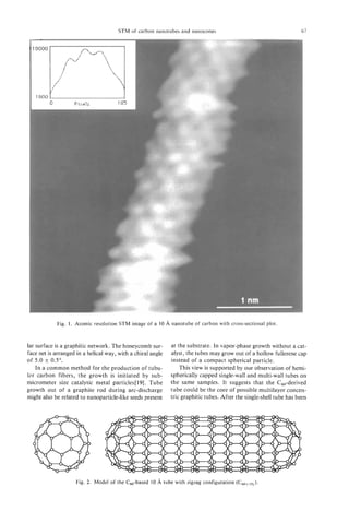
![68 K . SATTLER
*
4.00
3.00
2.00
1u.4
20.8
31.2 ns
1.00
Fig. 3. STM images of fullerene tubes on a graphite
substrate.
0
0 1.00 2.00 3.00 4,00
formed, further concentric shells can be added by gra- nu
phitic cylindrical layer growth.
Fig. 4. Atomic resolution STM image of a carbon tube, 35 A
The c60+10i (j = 1,2,3, . . . ) tube has an outer di- in diameter. In addition to the atomic structure, a zigzag su-
ameter of 9.6 A[18]. In its armchair configuration, the perpattern along the tube axis can be seen.
hexagonal rings are arranged in a helical fashion with
a chiral angle of 30 degrees. In this case, the tube axis
is the five-fold symmetric axis of the C60-cap. The
single-shell tube can be treated as a rolled-up graph- fect graphitic cylinders. The bundle is disturbed in a
ite sheet that matches perfectly at the closure line. small region in the upper left part of the image. In the
Choosing the cylinder joint in different directions closer view in Fig. 6, we recognize six tubes at the bun-
leads to different helicities. One single helicity gives dle surface. The outer shell of each tube is broken, and
a set of discrete diameters. To obtain the diameter that an inner tube is exposed. We measure again an inter-
matches exactly the required interlayer spacing, the tube spacing of -3.4 A.This shows that the exposed
tube layers need to adjust their helicities. Therefore, inner tube is the adjacent concentric graphene shell.
in general, different helicities for different layers in a The fact that all the outer shells of the tubes in the
multilayer tube are expected. In fact, this is confirmed bundles are broken suggests that the tubes are strongly
by our experiment. coupled through the outer shells. The inner tubes,
In Fig. 4 we observe, in addition to the atomic lat- however, were not disturbed, which indicates that the
tice, a zigzag superpattern along the axis at the sur-
face of the tube. The zigzag angle is 120" and the
period is about 16 A. Such superstructure (giant lat-
tice) was found earlier for plane graphite[lO]. It is a
Moire electron state density lattice produced by dif-
ferent helicities of top shell and second shell of a tube.
The measured period of 16 A reveals that the second
I
layer of the tube is rotated relative to the first layer
by 9". The first and the second cylindrical layers,
therefore, have chiral angles of 5" and -4", respec-
tively. This proves that the tubes are, indeed, com-
I
posed of at least two coaxial graphitic cylinders with
different helicities.
5. BUNDLES D
In some regions of the samples the tubes are found
to be closely packed in bundles[20]. Fig. 5 shows a
-200 A broad bundle of tubes. Its total length is
2000 A,as determined from a larger scale image. The
diameters of the individual tubes range from 20-40 A. ....
They are perfectly aligned and closely packed over the
Fig. 5. STM image of a long bundle of carbon nanotubes.
whole length of the bundle. The bundle is partially broken in a small area in the upper
Our atomic-resolution studies[ 101 did not reveal left part of the image. Single tubes on the flat graphite sur-
any steps or edges, which shows that the tubes are per- face are also displayed.](https://image.slidesharecdn.com/13709313-carbon-nanotubes-120928071547-phpapp01/85/13709313-carbon-nanotubes-81-320.jpg)
![STM of carbon nanotubes and nanocones 69
Fig. 6 . A closer view of the disturbed area of the bundle in Fig. 7 . A (244 A) STM image of two fullerene cones.
Fig. 5 ; the concentric nature of the tubes is shown. The outer-
most tubes are broken and the adjacent inner tubes are
complete.
is a hexagon network, while the apex contains five
pentagons. The 19.2" cone has mirror symmetry
through a plane which bisects the 'armchair' and 'zig-
intertube interaction is weaker than the intratube in- zag' hexagon rows.
teraction. This might be the reason for bundle forma- It is interesting that both carbon tubules and cones
tion in the vapor phase. After a certain diameter is have graphene networks. A honeycomb lattice with-
reached for a single tube, growth of adjacent tubes out inclusion of pentagons forms both structures.
might be energetically favorable over the addition of However, their surface nets are configured differently.
further concentric graphene shells, leading to the gen- The graphitic tubule is characterized by its diameter
eration of bundles. and its helicity, and the graphitic cone is entirely char-
acterized by its cone angle. Helicity is not defined for
6 . CONES the graphitic cone. The hexagon rows are rather ar-
ranged in helical-like fashion locally. Such 'local he-
Nanocones of carbon are found[3] in some areas licity' varies monotonously along the axis direction of
on the substrate together with tubes and other the cone, as the curvature gradually changes. One can
mesoscopic structures. In Fig. 7 two carbon cones are
displayed. For both cones we measure opening angles
A
of 19.0 f 0.5". The cones are 240 and 130 A long.
Strikingly, all the observed cones (as many as 10 in a
(800 A)2 area) have nearly identical cone angles - 19".
At the cone bases, flat or rounded terminations
were found. The large cone in Fig. 7 shows a sharp
edge at the base, which suggests that it is open. The
small cone in this image appears closed by a spherical-
shaped cap.
We can model a cone by rolling a sector of a sheet
around its apex and joining the two open sides. If the
sheet is periodically textured, matching the structure
at the closure line is required to form a complete net-
work, leading to a set of discrete opening angles. The
higher the symmetry of the network, the larger the set.
In the case of a honeycomb structure, the sectors with
angles of n x (2p/6) (n = 1,2,3,4,5) can satisfy per-
fect matching. Each cone angle is determined by the
corresponding sector. The possible cone angles are
19.2", 38.9", 60", 86.6", and 123.6", as illustrated in
Fig. 8. Only the 19.2" angle was observed for all the
cones in our experiment. A ball-and-stick model of the Fig. 8. The five possible graphitic cones, with cone angles
19.2" fullerene cone is shown in Fig. 9. The body part of 19.2", 38.9", 60", 86.6", and 123.6".](https://image.slidesharecdn.com/13709313-carbon-nanotubes-120928071547-phpapp01/85/13709313-carbon-nanotubes-82-320.jpg)
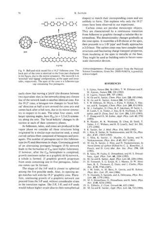
![TOPOLOGICAL AND SP3 DEFECT STRUCTURES
IN NANOTUBES
T. W. EBBESEN' T. TAKADA~
and
'NEC Research Institute, 4 Independence Way, Princeton, NJ 08540, U.S.A.
2Fundamental Research Laboratories, NEC Corporation, 34 Miyukigaoka, Tsukuba 305, Japan
(Received 25 November 1994; accepted 10 February 1995)
Abstract-Evidence is accumulating that carbon nanotubes are rarely as perfect as they were once thought
to be. Possible defect structures can be classified into three groups: topological, rehybridization, and in-
complete bonding defects. The presence and significance of these defects in carbon nanotubes are discussed.
It is clear that some nanotube properties, such as their conductivity and band gap, will be strongly affected
by such defects and that the interpretation of experimental data must be done with great caution.
Key Words-Defects, topology, nanotubes, rehybridization.
1. INTRODUCTION 2. CLASSES OF DEFECTS
Carbon nanotubes were first thought of as perfect Figure 1 show examples of nanotubes that are far
seamless cylindrical graphene sheets -a defect-free from perfect upon close inspection. They reveal some
structure. However, with time and as more studies of the types of defects that can occur, and will be dis-
have been undertaken, it is clear that nanotubes are cussed below. Having defined a perfect nanotube as
not necessarily that perfect; this issue is not simple be- a cylindrical sheet of graphene with the minimum
cause of a variety of seemingly contradictory observa- number of pentagons at each tip to form a seamless
tions. The issue is further complicated by the fact that structure, we can classify the defects into three groups:
the quality of a nanotube sample depends very much 1) topological defects, 2) rehybridization defects and
on the type of machine used to prepare it[l]. Although 3) incomplete bonding and other defects. Some defects
nanotubes have been available in large quantities since will belong to more than one of these groups, as will
1992[2], it is only recently that a purification method be indicated.
was found[3]. So, it is now possible to undertakevarious
accurate property measurements of nanotubes. How- 2.1 Topological defects
ever, for those measurements to be meaningful, the The introduction of ring sizes other than hexagons,
presence and role of defects must be clearly understood. such as pentagons and heptagons, in the graphene
The question which then arises is: What do we call sheet creates topological changes that can be treated
a defect in a nanotube? To answer this question, we as local defects. Examples of the effect of pentagons
need to define what would be a perfect nanotube. and heptagons on the nanotube structure is shown in
Nanotubes are microcrystals whose properties are Fig. 1 (a). The resulting three dimensional topology
mainly defined by the hexagonal network that forms follows Euler's theorem[8] in the approximation that
the central cylindrical part of the tube. After all, with we assume that all the individual rings in the sheet are
an aspect rat.io (length over diameter) of 100 to 1000, flat. In other words, it is assumed that all the atoms
the tip structure will be a small perturbation except of a given cycle form a plane, although there might
near the ends. This is clear from Raman studies[4] and be angles between the planes formed in each cycle. In
is also the basis for calculations on nanotube proper- reality, the strain induced by the three-dimensional ge-
ties[5-71. So, a perfect nanotube would be a cylindrical ometry on the graphitic sheet can lead to deformation
graphene sheet composed only of hexagons having a of the rings, complicating the ideal picture, as we shall
minimum of defects at the tips to form a closed seam- see below.
less structure. From Euler's theorem, one can derive the follow-
Needless to say, the issue of defects in nanotubes ing simple relation between the number and type of
is strongly related to the issue of defects in graphene. cycles nj (where the subscript i stands for the number
Akhough earlier studies of graphite help us under- of sides to the ring) necessary to close the hexagonal
stand nanotubes, the concepts derived from fullerenes network of a graphene sheet:
has given us a new insight into traditional carbon ma-
terials. So, the discussion that follows, although aimed 3n, + 2n, + n5 - n7 - 2n8 - 372, = 12
at nanotubes, is relevant to all graphitic materials.
First, different types of possible defects are described. where 12 corresponds to a total disclination of 4n (i.e.,
Then, recent evidences for defects in nanotubes and a sphere). For example, in the absence of other cycles
their implications are discussed. one needs 12 pentagons (ns)in the hexagonal net-
71](https://image.slidesharecdn.com/13709313-carbon-nanotubes-120928071547-phpapp01/85/13709313-carbon-nanotubes-84-320.jpg)
![12 T. W. EBBESEN T. TAKADA
and
Fig. 1. Five examples of nanotubes showing evidence of defects in their structure (p: pentagon, h: hep-
tagon, d: dislocation); see text (the scale bars equal 10 nm).
work to close the structure. The addition of one hep- (notice the different spacing between the layers on the
tagon (n7)to the nanotube will require the presence left and right-hand side of the nanotube).
of 13 pentagons to close the structure (and so forth) Another common defect appears to be the aniline
because they induce opposite 60" disclinations in the structure that is formed by attaching a pentagon and
surface. Although the presence of pentagons (ns)and a heptagon to each other. Their presence is hard to de-
heptagons (n,) in nanotubes[9,10] is clear from the tect directly because they create only a small local de-
disclinations observed in their structures (Fig. la), we formation in the width of the nanotube. However,
are not aware of any evidence for larger or smaller cy- from time to time, when a very large number of them
cles (probably because the strain would be too great). are accidentally aligned, the nanotube becomes grad-
A single heptagon or pentagon can be thought of ually thicker and thicker, as shown in Fig. 1 (b). The
as point defects and their properties have been calcu- existence of such tubes indicates that such pairs are
lated[l I]. Typical nanotubes don't have large numbers probably much more common in nanotubes, but that
of these defects, except close to the tips. However, the they normally go undetected because they cancel each
point defects polygonize the tip of the nanotubes, as other out (random alignment). The frequency of oc-
shown in Fig. 2. This might also favor the polygonal- currence of these aligned 5/7 pairs can be estimated
ization of the entire length of the nanotube as illus- to be about 1 per 3 nm from the change in the diame-
trated by the dotted lines in Fig. 2. Liu and Cowley ter of the tube. Randomly aligned 5/7 pairs should be
have shown that a large fraction of nanotubes are po- present at even higher frequencies, seriously affecting
lygonized in the core[12,131. This will undoubtedly have the nanotube properties. Various aspects of such pairs
significant effects on their properties due to local re- have been discussed from a theoretical point of view
hybridization, as will be discussed in the next section. in the literature[l4,15]. In particular, it has been
The nanotube in Fig. 1 (e) appears to be polygonized pointed out by Saito et a1.[14] that such defect pairs](https://image.slidesharecdn.com/13709313-carbon-nanotubes-120928071547-phpapp01/85/13709313-carbon-nanotubes-85-320.jpg)
![Topological and sp3 defect structures in nanotubes 13
Fig. 1 continued.
can annihilate, which would be relevant to the anneal- ter or, to put it more accurately, it will have s p Z f L V
ing away of such defects at high temperature as dis- character. The size of CY will depend on the degree of
cussed in the next section. curvature of the bend. The complete folding of the
It is not possible to exclude the presence of other graphene sheet will result in the formation of a defect
unusual ring defects, such as those observed in graphitic line having strong sp3 character in the fold.
sheets[16,171. For example, there might be heptagon- We have shown elsewhere that line defects having
triangle pairs in which there is one sp3 carbon atom sp3 character form preferentially along the symmetry
bonded to 4 neighboring atoms, as shown in Fig. 3. axes of the graphite sheet[lb]. This is best understood
Although there must be strong local structural distor- by remembering that the change from sp2 to sp3 must
tions, the graphene sheet remains flat overa11[16,17]. naturally involve a pair of carbon atoms because a
This is a case where Euler’s theorem does not apply. double bond is perturbed. In the hexagonal network
The possibility of sp3 carbons in the graphene sheet of graphite shown in Fig. 4, it can be seen that there
brings us to the subject of rehybridization. are 4 different pairs of carbon atoms along which the
sp3 type line defect can form. Two pairs each are
2.2 Rehybridization defects found along the [loo] and [210] symmetry axes. Fur-
The root of the versatility of carbon is its ability thermore, there are 2 possible conformations, “boat”
to rehybridize between sp, s p 2 , and sp3. While dia- and “chair,” for three of these distinct line defects and
mond and graphite are examples of pure sp3 and sp2 a single conformation of one of them. These are illus-
hybridized states of carbon, it must not be forgotten trated in Fig. 5 .
that many intermediate degrees of hybridization are In the polygonized nanotubes observed by Liu and
possible. This allows for the out-of-plane flexibility of Cowley[12,13], the edges of the polygon must have
graphene, in contrast to its extreme in-plane rigidity. more sp3 character than the flat faces in between.
As the graphene sheet is bent out-of-plane, it must lose These are defect lines in the sp2 network. Nanotubes
some of its sp2 character and gain some sp3 charac- mechanically deformed appear to be rippled, indicat-](https://image.slidesharecdn.com/13709313-carbon-nanotubes-120928071547-phpapp01/85/13709313-carbon-nanotubes-86-320.jpg)
![74 T. W. EBBESEN T. TAKADA
and
/
/
/
/ /
/
,/
/
. /
/ /
/
/
/
/
/
Fig. 2. Nanotube tip structure seen from the top; the pres-
ence of pentagons can clearly polygonize the tip.
2.3 Incomplete bonding and other defects
Defects traditionally associated with graphite might
also be present in nanotubes, although there is not yet
much evidence for their presence. For instance, point
defects such as vacancies in the graphene sheet might
be present in the nanotubes. Dislocations are occasion-
ally observed, as can be seen in Fig. 1 (c) and (d), but
they appear to be quite rare for the nanotubes formed
at the high temperatures of the carbon arc. It might
be quite different for catalytically grown nanotubes.
In general, edges of graphitic domains and vacancies
should be chemically very reactive as will be discussed
below.
3. DISCUSSION
There are now clear experimental indications that
nanotubes are not perfect in the sense defined in the
introduction[l2,13,19,20]. The first full paper dedi-
cated to this issue was by Zhou et al.[19], where both
pressure and intercalation experiments indicated that
the particles in the sample (including nanotubes) could
not be perfectly closed graphitic structures. It was pro-
I
Fig. 1 continued.
ing the presence of ridges with sp3 character[l8]. Be-
cause the symmetry axes of graphene and the long axis
of the nanotubes are not always aligned, any defect
line will be discontinuous on the atomic scale as it tra-
verses the entire length of the tube. Furthermore, in
the multi-layered nanotubes, where each shell has a
different helicity, the discontinuity will not be super-
imposable. In other words, in view of the turbostratic
nature of the multi-shelled nanotubes, an edge along
the tube will result in slightly different defect lines in Fig. 3. Schematic diagram of heptagon-triangle defects
each shell. [ 16,171.](https://image.slidesharecdn.com/13709313-carbon-nanotubes-120928071547-phpapp01/85/13709313-carbon-nanotubes-87-320.jpg)
![Topological and sp3 defect structures in nanotubes 15
inwards, layer by layer[21,22]. If there were smaller
domains along the cylindrical part, their edges would
be expected to react very fast to oxidation, contrary
to observation. Second, ESR studies[23] do not reveal
any strong signal from dangling bonds and other de-
fects, which would be expected from the numerous
edges in the paper-machk model.
To try to clarify this issue, we recently analyzed
crude nanotube samples and purified nanotubes be-
fore and after annealing them at high temperature[20].
It is well known that defects can be annealed away at
high temperatures (ca. 285OOC). The annealing effect
was very significant on the ESR properties, indicating
clearly the presence of defects in the nanotubes[20].
However, our nanotubes do not fit the defect struc-
ture proposed in the paper-machi model for the rea-
Fig. 4. Hexagonal network of graphite and the 4 different
pairs of carbon atoms across which the sp3-likedefect line son discussed in the previous paragraph. Considering
may form[l8]. the types of possible defects (see part 2), the presence
of either a large number of pentagon/heptagon pairs
in the nanotubes and/or polygonal nanotubes, as ob-
served by Liu and Cowley[12,13], could possibly ac-
posed that nanotubes were composed of pieces of gra- count for these results. Both the 5/7 pairs and the
phitic sheets stuck together in a paper-machi model. edges of the polygon would significantly perturb the
The problem with this model is that it is not consis- electronic properties of the nanotubes and could be
tent with two other observations. First, when nano- annealed away at very high temperatures. The sensi-
tubes are oxidized they are consumed from the tip tivity of these defects to oxidation is unknown.
In attempting to reconcile these results with those
of other studies, one is limited by the variation in sam-
ple quality from one study to another. For instance,
lb =C IESR measurements undertaken on bulk samples in
three different laboratories shoq7 very different re-
sults[19,23,24]. As we have pointed out elsewhere, the
quantity of nanotubes (and their quality) varies from
a few percent to over 60% of the crude samples, de-
pending on the current control and the extent of cool-
ing in the carbon arc apparatus[l]. The type and
distribution of defects might also be strongly affected
by the conditions during nanotube production. The ef-
fect of pressure on the spacing between the graphene
sheets observed by Zhou et al. argues most strongly
in favor of the particles in the sample having a non-
closed structure[l9]. Harris et a . actually observe that
f
nanoparticles in these samples sometimes do not form
closed structures[25]. It would be interesting to repeat
the pressure study on purified nanotubes before and
after annealing with samples of various origins. This
should give significant information on the nature of
the defects. The results taken before annealing will,
no doubt, vary depending on where and how the sam-
ple was prepared. The results after sufficient anneal-
ing should be consistent and independent of sample
origin.
4. CONCLUSION
The issue of defects in nanotubes is very important
in interpreting the observed properties of nanotubes.
For instance, electronic and magnetic properties will
Fig. 5 . Conformations of the 4 types of defect lines that can be significantly altered as is already clear from obser-
occur in the graphene sheet[l8]. vation of the conduction electron spin resonance[20,23].](https://image.slidesharecdn.com/13709313-carbon-nanotubes-120928071547-phpapp01/85/13709313-carbon-nanotubes-88-320.jpg)
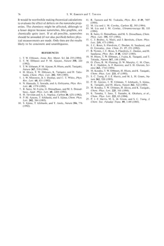
![HELICALLY COILED AND TOROIDAL CAGE FORMS
OF GRAPHITIC CARBON
SIGEOIHARA and SATOSHI
ITOH
Central Research Laboratory, Hitachi Ltd., Kokubunji, Tokyo 185, Japan
(Received 22 August 1994; accepted in revised form 10 February 1995)
Abstract-Toroidal forms for graphitic carbon are classified into five possible prototypes by the ratios
of their inner and outer diameters, and the height of the torus. Present status of research of helical and
toroidal forms, which contain pentagons, hexagons, and heptagons of carbon atoms, are reviewed. By
molecular-dynamics simulations, we studied the length and width dependence of the stability of the elon-
gated toroidal structures derived from torus C240and discuss their relation to nanotubes. The atomic ar-
rangements of the structures of the helically coiled forms of the carbon cage for the single layer, which
are found to be thermodynamically stable, are compared to those of the experimental helically coiled forms
of single- and multi-layered graphitic forms that have recently been experimentally observed.
Key Words-Carbon, molecular dynamics, torus, helix, graphitic forms.
1. INTRODUCTION The toroidal and helical forms that we consider
here are created as such examples; these forms have
Due, in part, to the geometrical uniqueness of their
quite interesting geometrical properties that may lead
cage structure and, in part, to their potentially tech-
to interesting electrical and magnetic properties, as
nological use in various fields, fullerenes have been the
well as nonlinear optical properties. Although the
focus of very intense research[l]. Recently, higher
method of the simulations through which we evaluate
numbers of fullerenes with spherical forms have been
the reality of the structure we have imagined is omit-
available[2]. It is generally recognized that in the ful-
ted, the construction of toroidal forms and their prop-
lerene, C60, which consists of pentagons and hexa-
erties, especially their thermodynamic stability, are
gons formed by carbon atoms, pentagons play an
discussed in detail. Recent experimental results on to-
essential role in creating the convex plane. This fact
roidal and helically coiled forms are compared with
was used in the architecture of the geodesic dome in-
theoretical predictions.
vented by Robert Buckminster Fuller[3], and in tra-
ditional bamboo art[4] (‘toke-zaiku’,# for example).
By wrapping a cylinder with a sheet of graphite, we 2. TOPOLOGY OF TOROIDAL
can obtain a carbon nanotube, as experimentally ob- AND HELICAL FORMS
served by Iijima[S]. Tight binding calculations indicate
that if the wrapping is charged (i.e., the chirality of the 2.1 Tiling rule for cage structure
surface changes), the electrical conductivity changes:
of graphitic carbon
the material can behave as a semiconductor or metal
Because of the sp2 bonding nature of carbon at-
depending on tube diameter and chirality[6].
oms, the atoms on a graphite sheet should be con-
In the study of the growth of the tubes, Iijima nected by the three bonds. Therefore, we consider how
found that heptagons, seven-fold rings of carbon at- to tile the hexagons created by carbon atoms on the
oms, appear in the negatively curved surface. Theo- toroidal surfaces. Of the various bonding lengths that
retically, it is possible to construct a crystal with only can be taken by carbon atoms, we can tile the toroi-
a negatively curved surface, which is called a minimal dal surface using only hexagons. Such examples are
surface[7]. However, such surfaces of carbon atoms
provided by Heilbonner[8] and Miyazakif91.However,
are yet to be synthesized. The positively curved sur- the side lengths of the hexagons vary substantially. If
face is created by insertion of pentagons into a hex- we restrict the side length to be almost constant as in
agonal sheet, and a negatively curved surface is created graphite, we must introduce, at least, pentagons and
by heptagons. Combining these surfaces, one could, heptagons.
in principle, put forward a new form of carbon, hav- Assuming that the surface consists of pentagons,
ing new features of considerable technological inter- hexagons, and heptagons, we apply Euler’s theorem.
est by solving the problem of tiling the surface with Because the number of hexagons is eliminated by a
pentagons, heptagons, and hexagons. kind of cancellation, the relation thus obtained con-
tains only the number of pentagons and heptagons:
#At the Ooishi shrine of Ako in Japan, a geodesic dome fs- f, = 12(1-g), where fsstands for the number of
made of bamboo with three golden balls, which was the sym-
bol called “Umajirushi” used by a general named Mori Mis-
pentagons, f, the number of heptagons, and g is the
aemon’nojyo Yoshinari at the battle of Okehazama in 1560, genius (the number of topological holes) of the
has been kept in custody. (See ref. 141). surface.
77](https://image.slidesharecdn.com/13709313-carbon-nanotubes-120928071547-phpapp01/85/13709313-carbon-nanotubes-90-320.jpg)
![78 S. IHARA and S. ITOH
+
In the spherical forms (Le., g = 0), fs=f7 12. In c540 c576
C60,for example, there are no heptagons (f,= 0), so
that fs = 12. If the torus whose genius ( 8 ) is one,
fs=f7. As we mentioned in the introduction, penta-
gons and heptagons provide Gaussian positive and
negative curvatures, respectively. Therefore, penta-
gons should be located at the outermost region of the
torus and heptagons at the innermost.
Fig. 2. Optimized toroidal structures of Dunlap’s tori: (a)
torus C540 and (b) torus C576; pentagons and heptagons
2.2 Classifications of tori are shaded.
Here, the topological nature of the tori will be dis-
cussed briefly. Figure 1 shows the five possible pro-
totypes of toroidal forms that are considered to be
related to fullerenes. These structures are classified by created by the torus in our case, the properties of the
the ratios of the inner and outer diameters rj and r, , helix strongly depend on the types of the torus.
and the height of the torus, h. (Note that r, is larger
than Ti). As depicted in Fig. 1, if ri = r,, and h < ri, <
3. TOROIDAL FORMS OF GRAPHITIC CARBON
and h = (r, - r j )then the toroidal forms are of type
-
(A). If ri< r,, and r, - h, (thus h ( r , - rj))then the
-
type of the torus is of type (D). If ri - r, h , and 3.1 Construction and properties
h = (r, - rj)then the type of the torus is (B). In these of normal tori
tori, h - ( ro - ri) and we call them normal toroidal 3.1.1 Geometric construction of tori. Possible
forms. However, if h < ( r , - r ; ) ,then the type of the constructions of tori with pentagons, heptagons, and
<
torus is (C). Furthermore, If (ro - r j )<< h, then the hexagons of carbon atoms are given independently by
type of the torus is (E). These are the elongated toroi- Dunlap[lO], Chernozatonskii[ll], and us[12-171. In
dal forms, as we can see from the definition of type ref. [18], the method-of-development map was used
( C ) and (E). to define various structures of tori. For other tori, see
ref. [19].
2.3 Derivation of the helical forms By connecting the sliced parts of tubes, Dunlap
In constructing a helix, the bond lengths of the proposed toroidal structures C540and C576r both of
hexagons substantially vary without the introduction which have six-fold rotational symmetry; both contain
of pentagons and/or heptagons. Thus, to make a gra- twelve pentagon-heptagon pairs in their equators[ 101
phitic form, it may be a good hypothesis that a heli- (See Fig. 2). Dunlap’s construction of the tori connects
cal structure will consist of pentagons, hexagons, and carbon tubules (2L,O)and (L,L)of integer L in his no-
heptagons of carbon atoms. Therefore, a helical struc- tation[lO]. The bird’s eye view of the structures of tori
ture tiled by polygons was topologically constructed Csd0and C576are shown in Fig. 2. This picture is use-
by cutting the torus into small pieces along the toroi- ful for understanding the difference between Dunlap’s
dal direction and replacing them, having the same to- construction and ours. Dunlap’s tori belong to the
roidal direction, but slightly displaced upwards along Type (A) according to the classification proposed in
the axis. The helix thus created contains one torus per section 2.2.
pitch without loss of generality. Because the helix is Recently, we become aware that Chernozatonskii
hypothetically proposed some structures of different
types of toroidal forrns[ll], which belong to type (B)
of our classification. He proposed toroidal forms by
creating suitable joints between tubes. See Fig. 3 of
ref. [9]. He inserts octagons or heptagons into hexa-
gons to create a negatively curved surface, as Dunlap
and we did. His tori C,,, and C440 have five-fold ro-
tational symmetry as our tori, the number of pairs of
pentagons and hexagons is ten. But the pentagons (at
the outer surface) and the heptagons (at the inner sur-
face) are located in the equator of the tori as Dunlap.
Chernozatonskii’s tori may be in the intermediate
structure between Dunlap’s and ours, but two hepta-
gons (a kind of defect) are connected to each other
(which he called an Anna saddle). Since two heptagons
are nearest neighbors, his torus would be energetically
higher and would not be thermodynamically stable, as
Fig. 1. Five possible simple prototypes of the toroidal forms
of graphitic carbon. All cross-sections of the tube are square. the placement of the pentagons follows the isolated
Here ro, r i , and h are the outer and inner radii and height pentagon rule. Other types of toroidal forms, such as
of the torus, respectively. type (C) and (E), are discussed later in section 3.2.2.](https://image.slidesharecdn.com/13709313-carbon-nanotubes-120928071547-phpapp01/85/13709313-carbon-nanotubes-91-320.jpg)
![Helically coiled and toroidal cage forms of graphitic carbon 19
pentagons- heptagons ergies of the tori[12,20,21]. To confirm the thermo-
dynamic stability, simulations at higher temperatures
using a second-order equations-of-motion method
were also performed. For details see ref. [13].
For the tori c 3 6 0 , C240, c 5 4 0 , and C576, the values
of the cohesive energies per atom are -7.41, -7.33,
-7.40, and -7.39 eV, respectively. Because the torus
C240 has the highest ratio of the number of pentagons
and heptagons to hexagons among them, torus C240
affects the distortion caused by the insertion of pent-
Fig. 3. Pentagon-heptagon transformation: (a) five-fold ro-
tational surface of c,; (b) negatively curved surface created agons and heptagons. For tori C240 and c 3 6 0 , the dif-
by pentagon-heptagon transformation; (c) a part of the re- ference between them arises from the shape of the outer
maining surface in creating the C3, torus. surface of these tori, because the inner surfaces of
both are derived from the same surface of a spheri-
cal fullerene Ca with the same pentagon-to-heptagon
replacements. As we raise the temperature up to
Contrary to the previous models, our tori[12,13,
2000K, tori C360, C240, c540, and c 5 7 6 retained their
15-17] were derived from the c 0 fullerene because
6
stability, indicating that they will be viable once they
the inner surface of the tori was obtained by remov-
are formed.
ing the two parallel pentagons in c 6 0 , and replacing
3.1.3 Rotational symmetric properties of
the ten remaining pentagons with heptagons, as shown
tori. We will study the various rotational symmetries
in Fig. 3. The inner surface thus obtained forms arcs
of the tori. The k-rotational symmetric structures were
when cut by a vertical cross-section, and the outer sur-
prepared by cutting the ko symmetric torus along the
face of the torus was constructed by extending the arc
radius of curvature into ko equal pieces, and by con-
until the arc became closed. Because the great circle
tinuously combining the k pieces. Here k can be larger
of c 6 0 consists of ten polygons, the arc of the torus
or smaller than ko. Because torus C240 has five-fold
was also closed by connecting ten polygons (which
symmetry (ko = 9, each piece contains 48 atoms.
consists of a pentagon and a heptagon and eight hexa-
Thus, we generated tori C192, CZs8,c 3 3 6 , and C384for
gons). Finally, gaps were filled by hexagon rings.
k = 4 , 6 , 7 , and 8. For other tori, a similar procedure
Using the guiding condition thatf, =f7, we created tori
was used to generate various rotational symmetric
with 360 carbon atoms and with 240 carbon atoms as
forms[l5].
shown in Fig. 4 (a) and (b), respectively. The torus
The relaxed structures of the various (rotational)
C360[ 12,131 belongs to type (B) and the torus C240[151
symmetric toroidal forms were obtained by steepest
is type (D). As shown in Fig. 4,our tori belongs to the
decent molecular-dynamics simulations[ 151. For the
point group D 5 d . Note that tori c 3 6 0 turns out to be
elongated tori derived from torus C240, the seven-fold
derived from tubules (8, 2) and that none of the
rotational symmetry is found to be the most stable. Ei-
pentagon-heptagon pairs lies on the equator. In refs.
ther five-fold or six-fold rotational symmetry is the
[13] and [15], larger or smaller tori were derived by
most stable for the toroidal forms derived from tori
using the Goldberg transformation, where hexagons
c 3 6 0 and 0, respectively (see Fig. 5 ) .
are inserted into the original torus.
Because the cohesive energy of the fullerene c 6 0 is
3.1.2 Thermodynamicproperties. A molecular-
-7.29 eV/atom and that of the graphite sheet is -7.44
dynamics simulation method (using a steepest decent
eV/atom, the toroidal forms (except torus C192) are
method) with Stillinger-Weber potential is employed
energetically stable (see Fig. 5). Finite temperature
to optimize structures and to obtain the cohesive en-
molecular-dynamics simulations show that all tori (ex-
cept torus CL9Jare thermodynamically stable.
c360 c240
c360
c540
c240
Fig. 4. Optimized toroidal structures: (a) torus C3, and (b)
torus CZm; Pentagons and heptagons are shaded. The diam-
2a L
8 -7.454 5 6 7
eters of the tube of the stable torus C360determined by op- Rotational S y m m et r y
timization using molqcular dynamics with Stillinger-Weber
potential[21], is 8.8 A. The diameter of the hole is 7 . 8 A, Fig. 5 . Dependence of the cohesive energy of tori C360,
which is quite close to the diameter of fullerence CG0. C,,,, and C,,, on the rotational symmetry.](https://image.slidesharecdn.com/13709313-carbon-nanotubes-120928071547-phpapp01/85/13709313-carbon-nanotubes-92-320.jpg)
![80 S. IHARA and S. ITOH
3.1.4 Recent results of electronic calcula- 3.2.2 Elongated tori. The experiments, at the
tions. Total energy calculations or molecular orbital present time, suggest that the torus of type (D) with
calculations are necessary to explore electronic, opti- parallel fringes at a separation of 3.7 A, such as Cm,
cal, and chemical properties of toroidal forms. From is likely to exist. Thus, the type (C) structures having
the ab initio self-consistent field (SCF) calculation height of 3.7 A could exist. See Fig. 6.
[22] for the torus C120, the HOMO-LUMO (highest- If we consider the l / k part of the chain of the cir-
occupied-lowest-unoccupied molecular orbitals) gap, cle, the number of hexagons can be put nl and n2 for
which is responsible for the chemical stability, is 7.5 the outer and inner circle of the upper (or lower) hex-
eV. This is close to that of SCF calculation for C60of agonal chain (see Fig. 6 ) , respectively. Each upper and
7.4 eV. (If the value of the HOMO-LUMO gap is zero, lower hexagonal chain contains n: n + +
: 2 ( n l + n2)
the molecule is chemically active, thus unstable.) In atoms. The number of the hexagons along the height
SCF, the HOMO-LUMO is different from local den- is put L , where L is a positive integer. For torus C240,
sity approximation. For stability, ours is consistent n l = n2 = 3, and L = 1 and k = 5. If we elongate (by
with the result of the all-electron local density approx- putting hexagons for allowed locations) the thickness
imation calculation where the value is 1.0 eV for the of the tube, then ro - r , , nl - n2 increases. On the
HOMO-LUMO gap[23]. Recent tight-binding calcu- other hand, if we elongate the height of the torus, L
lation of the same author[24], indicates that the increases.
HOMO-LUMO gap for C360 is 0.3 eV. These values By inserting a cylindrical tube of hexagons, we
indicate that toroidal structures are chemically stable. stretch the length of the toroidal forms whose heights
The tight-binding calculation of the HOMO-LUMO are larger than the radii, by putting n, = n2 = 3, k =
gap for tori CSwand C576gives 0.04 eV and 0.02 eV, 5 and increasing L . The stretched toroidal forms we
respectively[101. thus obtained[l7], type (D), areCm, C3M), c4809 CW,
Our Huckel-type calculation for isomers of C,[ 161 C7m, CSm. . (See Fig. 7). These forms are links be-
.
indicates that the positions and directions of the poly- tween toroidal forms and short (nanometer-scale)
gons change the electronic structures substantially for length turn-over tubes. The values of the cohesive en-
C240or CzsO. Because of the geometrical complexity ergies for tori C X O ,c 3 6 0 7 C4g0, c600, C720, and c840
of the torus, any simple systematics, as have been are -7.338, -7.339, -7.409, -7.415, -7.419, and
found for the band gaps of the carbon nanotubes[6], -7.420 eV/atom, respectively. Note that their cohe-
could not be derived from our calculations. But, the sive energies decrease with increasing height of the tori
common characteristics of the isomers for C240 with (or L ) (i.e., number of hexagons). Simulations showed
large HOMO-LUMO gaps are that their inner and that these stretched toroidal forms are thermodynam-
outer tubes have the same helicities or that the penta- ically stable.
gons and heptagons are radially aligned. Note that the Using the torus c 2 g g of D 6 h which is derived from
HOMO-LUMO gap of the torus C240, which is shown the torus c240 of , shallow tori, type (D), are gen-
in Fig. 3 (b), is 0.497 eV. erated by putting L = I, k = 6, and n2 = 3, with vary-
ing nl (= 3,4, 5,6,7,8,9). Tori having D6hsymmetry
3.2. Results of the experiments are shown in Fig. 8.
and elongated tori In Table 1, cohesive energies for the tori (of L =
3.2.1 Results of the experiments. Several ex- 1, k = 6) for various n, and n2 are given. The cohe-
perimental groups try to offer support for the exis- sive energy is the lowest for nl - n2 = 0, and also has
tence of the toroidal form of graphitic carbon[25].
Transmission electron microscopy (TEM) images
taken by Iijima, Ajayan, and Ichihashi[26] provided
experimental evidence for the existence of pairs of
pentagons (outer rim) and heptagons (inner rim),
which are essential in creating the toroidal struc-
ture[lO-171, in the turn-over edge (or turn-around
edge[26]) of carbon nanometer-sized tubes. They sug-
gested that the pentagon-heptagon pairs appearing in
the turn-over edge of carbon nanotubes have some
symmetry along the tube axis. They used a six-fold
symmetric case where the number of pentagon-
heptagon pairs is six. This accords with the theoretical
consideration that the five-, six-, seven-fold rotational
symmetric tori are most stable.
Iijima et al. also showed that the parallel fringes
appearing in the turn-over edge of carbon nanotubes
have a separation of 3.4 A[26]. (This value of sepa-
Fig. 6 . Part of the elongated torus: here, n,, n2,and L are
ration in nested tubes is also supported by other au- the number of the hexagons along the inner circle, outer cir-
thors[27].) It is quite close to that of the “elongated” cle, and height of the torus, respectively; this figure is for the
toroidal form of C proposed by us[15].
, case of n , = 12, n2 = 6 , and L = 1.](https://image.slidesharecdn.com/13709313-carbon-nanotubes-120928071547-phpapp01/85/13709313-carbon-nanotubes-93-320.jpg)
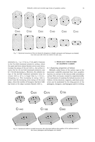
![82 S. IHARA and S. ITOH
Table 1. Cohesive energies of shallow tori; the parameters
n , and n2 are the number of hexagons along the outer and
inner circle, respectively (see Fig. 6). Here N is the number
of atoms in a torus
Energy
"I n2 N (eV/atom)
3 3 288 -7.376
4 3 420 -7.369
5 3 576 -7.375
6 3 756 -7.376
7 3 960 -1.315
8 3 1188 -7.372
9 3 1440 -7.369
4 4 384 -7.378
5 4 540 -7.368
6 4 720 -7.374
7 4 924 -7.374
8 4 1152 -7.372 Fig. 9. Helically coiled form C36g:one pitch contains a
9 4 1404 -7.370 torus C,,,. (a) coil length = 12.9 A and, (b) coil length =
6 6 576 -7.382 13.23 A. The tiling pattern of heptagons in the inner ridge
7 6 780 -7.369 line is changed, though the pattern of pentagons in the outer
8 6 1008 -7.373 ridge line remains upon changing the coil length.
9 6 1260 -7.372
10 6 1536 -7.370
11 6 1836 -7.368
12 6 2160 -7.366 hexagons, and heptagons per 360 and 540 atoms in the
helical structure are the same as in the torus C3h0 and
C,,,[13,14]. By pulling the helix coil, the coil length
for helix C360increases from 12.9 A (pitch angle a =
or twisting[29], in addition to changing the diameters 15.17 degrees, See Fig. 9 (a)) to 13.23 A (a = 19.73
(of the cross-sections) and the degree of helical ar- degrees, Fig. 9 (b)).
rangement as in straight tubes[6]; (2) a variety of ap- Because the second derivative of the cohesive en-
plications are expected because a variety of helical ergy with respect to the coil length provides the spring
structures can be formed; for instance, a helix with a constant, the spring constants of the helical structures
curved axis can form a new helix of higher order, such per pitch were estimated numerically. As shown in
as a super-coil or a super-super coil, as discussed Table 2, the spring constant for helix C360is 25 times
below. larger than that of helix C540. We found that the he-
lix C360is so stiff that the ring pattern changes. Al-
4.2 Properties for the helices derived though the pattern of the pentagons remains the same,
from normal tori the heptagons along the inner ridge line move their po-
The properties of optimized helical structures, sition and their pattern changes discretely with increas-
which were derived from torus C540 and C576rtype ing pitch angle a (from one stable pitch angle to the
(A), (proposed by Dunlap) and torus C360,type (B), other). See Fig. 9 (a) and (b); also see Fig. 3 of ref.
(proposed by us) by molecular dynamics were com- [14]. On the contrary, helix C540is found to be soft
pared. (see Figs. 9 (a) and 10). (Although the torus (i.e., a change in the pitch length does not change the
C576 is thermodynamically stable, helix c 5 7 6 was ring pattern of the surface). Thus, helix C540 can have
found to be thermodynamically unstable[l4]. Hereaf- relatively large values of a,which corresponds to the
ter, we use helix C, to denote a helix consisting of open-coiled form and can easily transform to the
one torus (C,) in one pitch. super-coiled form without changing the ring patterns.
The diameters of the inside and outside circles, the In ref. [14], helix Close was generated from helix C360
pitch length, and the cohesive energy per atom for he- by use of Goldberg transformation, where hexagons
lices are given in Table 2. The number of pentagons, are inserted into the original helix c 3 6 0 . Helix Close
Table 2. Structural parameters, cohesive energies per atom, and spring constant for helices
C,,, and C,,,; here ro and ri are outer and inner diameter of a helix, respectively
diameters
Pitch length Cohesive energy Spring constant
Structure r, (nm) r, (nm) (nm) (eV/atom) (meV/nm)
Helix C360 2.26 0.78 12.9 -7.41 (-7.41 torus) 4.09
Helix C,,, 4.14 2.94 8.5 -7.39 (-7.40 torus) 0.16](https://image.slidesharecdn.com/13709313-carbon-nanotubes-120928071547-phpapp01/85/13709313-carbon-nanotubes-95-320.jpg)
![Helically coiled and toroidal cage forms of graphitic carbon 83
Fig. 12. Elongated helical structures (a) helix C756and (b)
helix C2,60.
helix Cz160 (nl = 12, n2 = 6, L = 1) can be generated
(see Fig. 12). In these cases, the flat part (i.e., the part
Fig. 10. Helically coiled form C,,,: one pitch contains a
resembling the graphite layer) becomes wider and
torus C,,,.
wider with increasing n l . Thus, this type of helical
structure has minimal cohesive energy at n l - n2 =
0,2 as observed in the shallow tori.
was found to be stiffer than helix c360[14]. The dif-
ference in elasticity of the helically coiled forms of he- 4.4 Comparison with experiments
lices may be attributed to the difference in patterns of Ivanov et al.[31] and Van Tendeloo et al.[32] re-
the heptagons; these are sensitive to the geometric ported a synthesis of helically coiled multi-layered
properties, such as the ratio of the radii of the cross- form. They showed that: (1) cobalt on silica is the best
section and the curvature. catalyst-support combination for the production of
Because the tube diameter of the helix CSd0is graphite tubes, such as straight tubes and coiled ones,
small compared to the helix c360, atoms at the open and (2) decreasing temperature from 973 to 873K
ends must bend inwards to cover the open end. The leads to strong decrease in the amorphous carbon pro-
open end is covered with six hexagons, one heptagon, duction. Also, (3) helically coiled carbon tubes were
one square, and one pentagon, see Fig. 11. The elec- obtained with inner and outer diameter of 3-7 and 15-
tronic structure of helices is strongly affected by the 20 nm, respectively, and up to 30 pm in length. The
end pattern of the rings because the end rings of odd size of the helical structure is orders of magnitude
numbers play a scattering center, such as a disclina- smaller than the helix-shaped fibers composed of
tion center as discussed by Tamura and Tsukada[30]. amorphous carbon[28]. Note their sizes are much
The edge effect may lead to adding an exotic electronic larger than that of the theoretical one[l4]. (4) Using
character to the helical structure which is not seen in TEM and the electron diffraction method, they sug-
the straight tubes. gested that the helically coiled tubes consist of a reg-
ularly polygonized structure, where the bend may be
4.3 Helices derived from elongated tori related to pairs of pentagon-hexagon carbon rings in
From elongated tori, such as type (C), type (D), the hexagonal network as suggested by ref. [14]. ( 5 )
and type (E), helical structures are derived. For exam- As shown in Fig. 13, a helix-shaped nanotube with ra-
ple, from the type ( c ) elongated torus of Dbh, men-
tioned in 3.2.2, helix C756(nl = 6, n2 = 3, L = 1) and
--
Fig. 1 1 . Edge of the helix C540:(a) initial state and, (b) Fig. 13. TEM picture of a helix-shaped structure with radius
reconstructed form of the edge; the edge contains a square, of about 18 nm, pitch about 30 nm, containing 10 graphite
heptagon, pentagons and hexagons. tubes (after V. Ivanov et d.).](https://image.slidesharecdn.com/13709313-carbon-nanotubes-120928071547-phpapp01/85/13709313-carbon-nanotubes-96-320.jpg)
![84 S. IHARA and S. ITOH
Fig. 14. TEM picture of a single layered helix-shaped structure: a 1.3-nrn diameter helix coils around the
3.6 nrn tube (after C.H. Kiang ef al.).
dius of about 18 nm, pitch about 30 nm, has ten gra- than those of theoretically predicted ones. However,
phitic layered tubes (diameter of the innermost tube it should be noted that in ref. [14], we have pointed
is about 2.5 nm.). out the existence of the larger helices. We provide an
C.-H. Kiang et a1.[33] reported that the single- example of a large helical form: the helix Close can be
layered coiled tubes were obtained by co-vaporizing generated from helix C3m using the Goldberg algo-
cobalt with carbon in an arc fullerene generator. A rithm, as larger tori were derived from genetic one
single-layered helical structure with radii of curvature such as torus Clzo[ 141.
as small as 20 nm was seen. These helically coiled Zhang et al.[34] also provide a molecular model by
forms tend to bundle together. In the soot obtained connecting tubes at angle 30" bends by introducing the
with sulfur-containing anodes, they also found the required pairs of pentagons and hexagons in the hex-
1.3-nm diameter tube coil around the 3.6 nm tube (see agonal network. Their method is quite similar to Dun-
Fig. 14). This kind of structure was theoretically pro- lap's way of creating torus c 5 4 0 . They combined the
posed in ref. [14]. + + +
(12 9n,0) tube and (7 5n,7 5n) tube in the Dun-
By close analysis of diffraction pattern of catalyst- lap's notation, and also combined (9n,0)tube to
grown coiled tube, X. B. Zhang et a1.[34] reported the ( 5 n , 5 n ) tube to show the feasibility of the multi-
larger angular bends and their number to be about 12 layered helical forms. Combination of these tubes,
per helix turn (the magnitude of angular bends is however, leads to toroidal forms whose connection is
about 30 degrees), and this is the essential in determin- quite similar to that of torus c 5 4 0 . But the tori of
ing the geometry. Their smallest observed helixhas a Zhang et al. (see Fig. 15) can easily be turned into he-
radius of about 8 nm. Thus, their sizes are much larger lices by regularly rotating the azimuth of the succes-
sive lines connecting pentagon and heptagons with
small energy, as helix C540 as shown in ref. [14]. (To-
rus C540 can transform to helix C540without rebond-
ing the carbon atoms on the network with small
energy, as we showed in section 4.2.) See also ref. [35].
Good semi-quantitative agreements are found in
diffraction patterns and proposed models obtained by
molecular-dynamics[141, because the results of the ex-
periments[3 1-34] are consistent with the atomic mod-
els proposed by us[ 141. However, in the present state
of high-resolution electron microscopy, taking into ac-
count, moreover, the number of sheets and the com-
plicated geometry of the helix, it seems unlikely to
directly visualize the pentagon-hexagon pairs.
5. CONCLUSION
We showed the possible existence of various forms
of helically coiled and toroidal structures based on en-
ergetic and thermodynamic stability considerations.
Though the formation process of these structures is
not the subject of this work, the variety of patterns in
the outer and inner surface of the structures indicates
that there exist many different forms of stable cage
carbon structures[l0-19]. The molecules in a one-
I
dimensional chain, or a two-dimensional plane, or a
Fig. 15. Tori of Zhang et al.; a 30-degree connections of three-dimensional supermolecule are possible extended
tubes: a (12,O) segment and a (7,7) segment (After Zhang structures of tori with rich applications.
et al.). Many different coiled forms of stable cage carbon](https://image.slidesharecdn.com/13709313-carbon-nanotubes-120928071547-phpapp01/85/13709313-carbon-nanotubes-97-320.jpg)
![Helically coiled and toroidal cage forms of graphitic carbon 85
structures also exist. In the helically coiled form, coils Phys. Ref. B46, 1941 (1992). W. Y. Ching, Ming-Zhu
may be able to transform into other forms. It would Huang, and Young-nian-Xu, Phys. Rev. B46, 9910
(1992). Ming-Zhu Huang, W. Y. Ching, and T. Lenosky,
be interesting if the proposed structure and its variant
Phys. Rev. B47, 1593 (1992).
forms -combinations of helix with toroidal forms, he- 8. E. Heilbonner, Helv. Chim. Acta 37, 921 (1954).
lical coiling around the tube, nested helical forms, 9. K. Miyazaki, Polyhedra and Architecture (in Japanese),
coiled structure of higher order such as supercoil ob- pp. 270. Shokoku-sha, Tokyo (1979).
served in biological systems- could be constructed in 10. B. I. Dunlap, Phys. Rev. B46, 1933 (1992).
11. L. A. Chernozatonskii, Phys. Lett. A170, 37 (1992).
a controlled manner from the graphitic carbon cage. 12. S. Itoh, S. Ihara, and J. Kitakami, Phys. Rev. B47, 1703
Because the insertion of pentagons and heptagons into (1993).
hexagons changes the electronic structures[26], heli- 13. S. Ihara, S. Itoh, and J. Kitakami, Phys. Rev. B47,
cal and toroidal forms will have interesting electrical 12908 (1993).
and magnetic properties, which could not be seen in 14. S. Ihara, S. Itoh, and J. Kitakami, Phys. Rev. B48,5643
(1993).
the cylindrical tubes by modulation of the periodicity 15. S . Itoh and S. Ihara, Phys. Rev. B48, 8323 (1993).
of the appearance of the pentagon and hexagon 16. S. Itoh and S. Ihara, Phys. Rev. B49, 13970 (1994).
pairs[36]. 17. S. Ihara and S. Itoh, Proceedings of 22nd International
Conference on Physics of Semiconductors (Edited by
Acknowledgements-We are grateful to G. Van Tendeloo D. J. Lockwood), p. 2085. World Sci. Pub., Singapore
and D. S. Bethune for sending us TEM pictures of helically (1995).
coiled graphitic carbon. We are also grateful for the useful 18. M. Fujita, M. Yoshida, and E. Osawa, Fullerene Sei.
discussions with Masaru Tsukada, Ryo Tarnura, Kazuto Tech. (in press).
Akagi, and Jun-ichi Kitakami. We are also grateful for the 19. E. G . Gal'pern, I. V. Stankevich, A. L. Chistyakov, and
useful discussions with Toshiki Tajima, J. C. Greer, and Su- L. A. Chernozatonskii, Fullerene Sei. Technol. 2, 1
mio Iijima. (1994).
20. E H. Stillinger and T. A. Weber, Phys. Rev. B31, 5262
(1985). E H. Stillinger and T. A. Weber, Phys. Rev. B33,
REFERENCES 1451 (1986).
21. F. E Abraham and I. P. Batra, Surf. Sci. 209, L125
1. H. W. Kroto, J. R. Heath, S. C. O'Brieu, R. F. Curl, and (1989).
R. E. Smalley, Nature (London) 318, 162 (1985). W. 22. J. C. Greer, S. Itoh, and S. Ihara, Chem. Phys. Lett.
Kratschmer, L. D. Lamb, K. Fostiroropoulos, and D. R. 222, 621 (1994).
Huffman, Nature 347, 354 (1990). 23. M. R. Pederson, J. K. Johnson, and J. Q. Broughton,
2. F. Diederich, R. L. Whetten, C. Thilgen, R. Ettl, I. Bull. Am. Phys. Soc. 39, 898 (1994).
Chao, and M. M. Alverez, Science 254, 1768 (1991). K. 24. J. K. Johnson, Proceedings Materiuls Research Society
Kikuchi, N. Nakahara, T. Wakabayashi, M. Honda, H. Symposium, Fall, 1993 (to be published).
Matsumiya, T. Moriwaki, S. Suzuki, H. Shiromaru, K. 25. M. Endo (private communication).
Saito, K. Yamauchi, I. Ikemoto, and Y. Achiba, Chem. 26. S. Iijima, P. M. Ajayan, and T. Ichihashi, Phys. Rev.
Phys. Lett. 188, 177 (1992). D. Ugarte, Nature condon) Lett. 69, 3100 (1992). S. Iijima, T. Ichihashi, and Y.
359, 707 (1992). S. Iijima, J. Phys. Chem. 91, 3466 Ando, Nature (London) 356, 776 (1992).
(1987). 27. Y. Saito, T. Yoshikawa, S. Bandow, M. Tomita, and T.
3. R. Buckminster Fuller, US patent No. 2682235 (1954). Hayashi, Phys. Rev. B48, 1907 (1993).
4. Koji Miyazaki, Puraton to Gojyuunotou (Plat0 and Five- 28. H. Iwanaga, M. Kawaguchi, and S. Motojima, Jpn. J.
Storied Pagoda) (in Japanese) pp. 224. Jinbun-shoin, Appl. Phys. 32, 105 (1993). S. Motojirna, M. Kawa-
Kyoto, (1987). Koji Miyazaki, Fivefold Symmetry (Ed- guchi, K. Nozaki, and H. Iwanaga, Carbon 29, 379
ited by I. Hargittai) p. 361. World Sci. Pub, Singapore (1991). M. S. Dresselhaus and G. Dresselhaus, Adv.
( 1992). Phys. 30, 139 (1981).
5. S. Iijima, Nature (London) 354, 56 (1991). T. W. Eb- 29. W. R. Bauer, F. H. C. Crick, and J. H. White, Sci. Am.
besen and P. M. Ajayan, Nature 358, 220 (1992). S. 243, 100 (1980). F. H. C. Crick, Proc. Nati. Acad. Sci.
Iijima and T. Ichihashi, Nature (London) 363, 603 U.S.A. 73, 2639 (1976).
(1993). D. S. Bethune, C. H. Kiang, M. S. de Vries, G. 30. R. Tamura and M. Tsukada, Phys. Rev. B49, 7697
Gorman, R. Savoy, J. Vazquez, and R. Beyers, Nature (1994).
363, 605 (1993). 31. V. Ivanov, J. B. Nagy, Ph. Lambin, X. B. Zhang, X. E
6. J. W. Mintmire, B. I. Dunlap, and C. T. White, Phys. Zhang, D. Bernaerts, G. Van Tendeloo, S. Amelinckx,
Rev. Lett. 68,631 (1992). N. Hamada, S. Sawada, and and J. Van Landuyt, Chem. Phys. Lett. 223,329 (1994).
A. Oshiyama, Phys. Rev. Lett. 68, 1579 (1990). D. H. 32. G. Van Tendeloo, J. Van Landuyt, and S. Amelincx, The
Robenson, D. W . Brenner, and J. W . Mintmire, Phys. Electrochemical Society 185th Meeting, San Francisco,
Rev. B45, 12592 (1992). M. Fujita, M. Saito, G. Dres- California, May (1994).
selhaus, and M. S. Dresselhaus, Phys. Rev. B45, 13834 33. C. H. Kiang, W. A. Goddard 111, R. Beyers, J. R. Sa-
(1992). lem, and D. S. Bethune, J. Phys. chem. 98,6618 (1994).
7. A. L. Mackay and H. Terrones, Nature (London) 352, 34. X. B. Zhang, X. F. Zhang, D. Bernaerts, G. Van Tende-
762 (1991). T. Lenosky, X. Gonze, M. P. Teter, and V. loo, S. Amelinckx, J. Van Landuyt, V. Ivanov, J. B.
Elser, Nature 355, 333 (1992). D. Vanderbilt and J. Ter- Nagy, Ph. Lambin, and A. A. Lucas, Europhys. Lett.
soff, Phys. Rev. Lett. 68, 5 11 (1992). S. J. Townsend, 27, 141 (1994).
T. J. Lenosky, D. A. Muller, C. S. Nichols, and V. Elser, 35. B. I. Dunlap, Phys. Rev. B50, 8134 (1994).
Phys. Rev. Lett. 69, 921 (1992). R. Phillips, D. A. 36. K. Akagi, R. Tamura, M. Tsukada, S. Itoh, and S.
Drabold, T. Lenosky, G. B. Adams, and 0. F. Sankey, Ihara, Phys. Rev. Lett. 74, 2703 (1995).](https://image.slidesharecdn.com/13709313-carbon-nanotubes-120928071547-phpapp01/85/13709313-carbon-nanotubes-98-320.jpg)

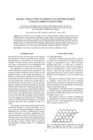
![88 A. FONSECA al.
et
I I
1-
I
-
- 1
1 = 2.46 A d=3a
parallel hexagon unit cell perpendicular hexagon unit cell
(1 for the (L,O) tubules) (d for the (L',L') tubules)
a = side of the hexagon in graphite
1 = width of the hexagon in graphite = a 6
Fig. 2. Building blocks for the construction of (L,O)and (L',L')tubules.
2.2 Connecting a ( L ,0) to a (L',L') tubule by As distinct from the ideal connection of Dunlap,
means of a knee we now describe the series of nanotubule knees
Dunlap describes the connection between (L,O) (9n,0)-(5n,5n),with n an integer. We call this series
and (L',L') tubules by means of knees. A knee is the perfectly graphitizable carbon nanotubules because
formed by the presence of a pentagon on the convex the difference of diameter between the two connected
and of a heptagon on the concave side of the knee. segments of each knee is constant for all knees of the
An example is illustrated in Fig. 3(a). The (12,O)-( 7,7) series (Fig. 4). The two straight tubules connected to
knee is chosen for illustration because it connects form the n = 1 knee of that series are directly related
two tubules whose diameters differ by only 1%. The to C60, the most perfect fullerene[15], as shown by
bent tubule obtained by that connection was called the fact that the (9,O)tubule can be closed by 1/2 C60
ideal by Dunlap[ 12,131. cut at the equatorial plane perpendicular to its three-
If one attempts to build a second coaxial knee fold rotation symmetry axis, while the ( 5 3 ) tubule
around the ideal (12,O)-(7,7) knee at an interlayer can be closed by 1/2 C60 cut at the equatorial plane
distance of 3.46A, the second layer requires a perpendicular to its fivefold rotation symmetry axis
(21,O)-( 12,12) knee. In this case, the axis going [Fig. 5(a)].
through the centers of the heptagon and of the As a general rule, any knee of the series
pentagon of each tubule are not aligned. Moreover, (9n,0)-(5n,5n) can be closed by 1/2 of the fullerene
the difference of diameter between the two connected C(60,n~). that, for this multilayer series, there is
Note
segments of each knee is not the same for the two a single axis going through the middle of the hepta-
knees [Fig. 3(b)]. gons and pentagons of any arbitrary number of
Fig. 3. (a) Model structure of the (12,O)-(7,7) knee, shown along the 5-7 ring diameter, (b) model
structure of the (21,O)-( 12,12) knee (ADiam, + l%), separated from the (12,O)-(7,7) knee (ADiam. - 1%)
= =
by the graphite interplanar distance (3.46 A).](https://image.slidesharecdn.com/13709313-carbon-nanotubes-120928071547-phpapp01/85/13709313-carbon-nanotubes-101-320.jpg)
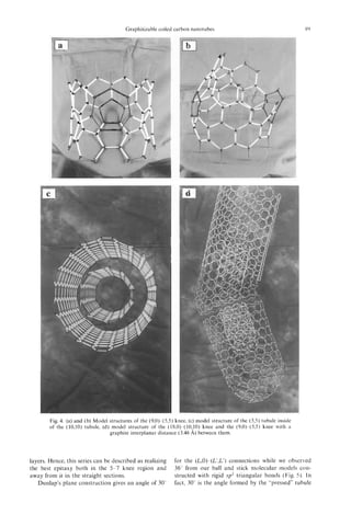
![90 A. FONSECAal.
et
Fig. 5. Model structure of the (9,O)-(5,5) curved nanotubule ended by two half C,, caps (a) and of the
(12,O)-(7,7) curved nanotubule (b). A knee angle of 36” is observed in both models.
knee if the five and seven membered rings are nanotubule series,-the diameter of the graphite layer
removed. By folding the knee to its three-dimensional n is equal to 6.9n0A,within 2%, so that the interlayer
shape, the real angle expands to 36”. At the present distance is 3.46 A. For this interlayer distance, the
time, it is not known whether this discrepancy is an smallest possible knee is (5,O)-( 3,3), with a diameter
artefact of the ball and stick model based on sp2 of 3.99 A (Table l ) , because the two smaller ones
bonds or whether strain relaxation around the knee could not give layers at the graphitic distance. Note
demands the 6” angle increase. Electron diffraction that all the n=O tubules are probably unstable due
and imaging data[8-101 have not so far allowed to their excessive strain energy[ 161.
assessment of the true value of the knee angle in The nanotube connections whose diameter differ-
polygonized nanotubes. ences are different from the 3.8% value characteristic
The diameters (D,) of the perfectly graphitized to the (9n,0)-( 5n,5n) series, will tend to that value
series are Dnl= 15naln. and D n , , = 9 n u f i / x , respec- with increasing the graphite layer order n.
tively, for the “perpendicular” and “parallel” straight The inner (outer) diameter of the observed curved
segments. D,,, is 3.8% larger than DnL.This diameter or coiled nanotubules produced j y the catalytic
method[8] varies from 20 to 100 A (150 to 200 A),
difference is larger than the 1% characterising the
which corresponds to the graphite layer order
(12,O)-(7,7) ideal connection of Dunlap[ 12,131, but
3 1 n 1 1 5 (Table 1).
it is independent of n. A few percent diameter differ-
ence can easily be accommodated by bond relaxation 2.3 Description of a perfectly graphitizable chiral
over some distance away from the knee. tubule knee series
Table 1 gives the characteristics of classes of Among all the chiral nanotubules connectable by
+ +
bent tubules built on ( 9 n + x , 0)-(5n y, 5n y) knee a knee, the series (8n,n)-(6n,4n), with n an integer, is
connections. In these classes, y = ( x / 2 ) f1, and the perfectly graphitizable. For that series, the diameter
integers x and y are selected to give small relative of the graphite layer of order n is equal to 6.7% 4,
diameter differences, so that within 1%, so that the interlayer distance is 3.38 A.
Moreover, the two chiral tubules are connected by a
barn. -Dnl)lDn//, Dnl= ( 5n +Y)3
=(Dn// 4 ~ pentagon-heptagon knee, with the equatorial plane
and Dn,,=(9n+x)u$/n. passing through the pentagon and heptagon as for
the (9n,0)-( 5n,5n) series. On the plane graphene con-
The first layers of the connections leading to the struction, the two chiral tubules are connected at an
minimum diameter difference are also described in angle of 30”. As for the (9n,O)-(Sn,Sn) series, 36” is
Table 1. For the general case, contrary to the observed from our ball and stick molecular model
(9n,O)-(Sn,Sn) knees, the largest side of the knee is constructed with rigid sp2 triangular bonds (Fig. 6).
not always the parallel side ( 9 n + x , 0). As seen in
Table 1, the connections (7,O)-(4,4) and (14,O)-(8,s) 2.4 Constructing a torus with (9n,0)-(5n,5n)
are, from the diameter difference point of view, as knees
ideal as the (12,O)-(7,7) described by Dunlap[ 12,131. Building up a torus using the (9,O)-( $5) knee
For the perfectly graphitizable (9n,0)-( 5n,5n) [Fig. 7(a)] is compatible with the 36” knee angle.](https://image.slidesharecdn.com/13709313-carbon-nanotubes-120928071547-phpapp01/85/13709313-carbon-nanotubes-103-320.jpg)
![Graphitizable coiled carbon nanotubes 91
Table 1. Characteristics of some knees with minimal diameter difference
0 3 2 - 15.5 2.53
0 4 2 13.4 2.92
0 5 3 - 3.9 3.99
0 6 3 13.4 4.38
0 7 4 1.o 5.45
0 8 5 - 8.2 6.52
1 0 0 3.8 6.914
1 1 1 - 3.9 7.98
1 2 1 5.5 8.38
1 3 2 - 1.0 9.44
1 4 3 - 6.6 10.51
1 5 3 1.o 10.91
1 6 4 - 3.9 11.98
1 7 4 2.6 12.37
1 8 5 - 1.9 13.44
2 0 0 3.8 13.83
Fig. 6. Model structure of the (8,l)-(6,4) knee extended by two straight chiral tubule segments.
This torus contains 520 carbon atoms and 10 knees The (9,O)-( 5,s) torus represented in Fig. 7( b) con-
with the heptagons on the inner side forming abutting tains 10 straight segments of 38 atoms each joining
pairs. It has a fivefold rotation symmetry axis and if at 10 knees. The sides of each knee have been
it is disconnected at an arbitrary cross section, all the elongated by the addition of hexagonal rings. (The
carbons remain at their position because there is no picture of that torus and of the derived helices are
strain. This is also the case for the C9,,,, torus presented given in the literature[ 111.) The corresponding gen-
in Fig. 7(b), where each segment is elongated by two eral formula giving the number of atoms in such
circumferential rings. At each knee, the orientation elongated knees is:
of the hexagons changes from parallel to perpendicu-
lar and vice versa. N,,== N , + cn (2)
The number of atoms forming the smallest n = l The constant c [equal to 38 for the torus of Fig. 7 (b)]
knee of the (9n,0)-(5n,5n) series is 57 and it leads to gives the length of the straight segment desired, with
the C520 torus having adjacent heptagons. The +
c =20(Hex,) 18(Hexii) where, Hex, and Hexi, are
number of atoms of any knee of that series is given the numbers of hexagonal rings extending the knee
by: in the appropriate direction. The smallest N , knee
[Fig. 8(a) for n = l ] , and the way of constructing
+
N , = 24n2 33n (1) prolonged N,,c knees [Fig. 8(b) for n = 1 and c = 381
As the N , knee can have n - 1 inner concentric knees, are represented in Fig. 8. In that plane or “pressed
all of them separated by approximately the graphite tubule” figure, only one half of the knee is shown.
interplanar distance, n is called the “graphite layer For symmetry reasons, the median plane of the N,,c
order”. In fact, the number of atoms of the torus n is knees crosses the knee at the same position as the
given by 10(24n2+33n-5n) because 10n atoms are limits of the corresponding knee does on a planar
common for adjacent knees at the (5n,5n)-( 5n,5n) representation (Fig. 8). The dotted bonds are the
connection (see below, Section 2.5). borders between the knee and the next nanotubes or](https://image.slidesharecdn.com/13709313-carbon-nanotubes-120928071547-phpapp01/85/13709313-carbon-nanotubes-104-320.jpg)
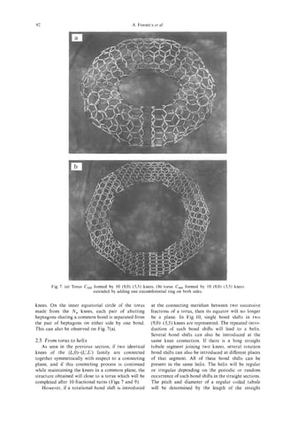
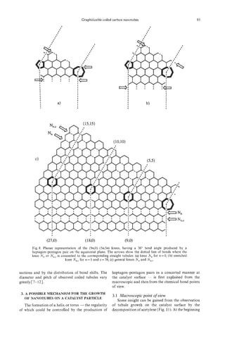
![94 A. FONSECAal.
et
(9,O) to (9,O) parallel connection
(53)to ( 5 3 ) perpendicular connection
(9,O) parallel connection
( 5 3 ) to ( 5 5 ) perpendicular connection
Fig. 9. Planar representation of (9,O) to (9,O) and (5,5) to ( 5 3 ) connections of (9,O)-(5,5) knees leading
to a torus. The arrows indicate the location of the connections between the Nn,cknees.
of the tubule production by the catalytic method, this leads to the tightly wound helices already
many straight nanotubes are produced in all direc- observed [4,5].
tions, rapidly leading to covering of the catalyst However, if there is a second obstacle to tubule
surface. After this initial stage, a large amount of growth [B in Fig. 12(f)-(h)], forcing the tubule to
already started nanotubes will stop growing, probably rotate at the catalyst particle, the median planes of
owing to the misfeeding of their active sites with two successive knees will be different and the resulting
acetylene or to steric hindrance. The latter reason is tubule will be a regular helix. Note that the catalyst
in agreement with the mechanism already suggested particle itself could act as the second obstacle B. The
by Amelinckx et aL[10], whereby the tubule grows obstacles A and B of Fig. 12 axe hence considered as
by extrusion out of the immobilized catalyst particle. the bending driving forces in Fig. 11, with A regulat-
It is also interesting to point out that in Fig. 11 there ing the length of the straight segments (9n,0)and
is no difference between the diameters of young (5n,5n) and B controlling the rotation angle or
[Fig. ll(a)] and old [Fig. ll(c)] nanotubes. number of rotational bond shifts (Fig. 10).
Since regular helices with the inner layer matching From the observation of the early stage of nano-
the catalyst particle size have been observed[4,5], tube production by the catalytic decomposition of
we propose a steric hindrance model to explain the acetylene, it is concluded that steric hindrance arising
possible formation of regular and tightly wound from the surrounding nanotubes, graphite, amor-
helices. phous carbon, catalyst support and catalyst particle
If a growing straight tubule is blocked at its itself could force bending of the growing tubules.
extremity, one way for growth to continue is by
forming a knee at the surface of the catalyst, as
sketched in Fig. 12. Starting from the growing tubule 3.2 Chemical bond point of view
represented in Fig. 12(a), after blockage by obstacle To form straight cylindrical carbon nanotubes,
A [Fig. 12(b)], elastic bending can first occur one possibility is for the carbon hexagons to be
[Fig. 12(c)]. Beyond a certain limit, a knee will appear “bonded” to the catalyst surface during the growth
close to the catalyst particle, relaxing the strain and process. In that “normal” case, one of the edges of
freeing the tubule for further growth [Fig. 12(d)]. If the growing hexagons remains parallel to the catalyst
there is a single obstacle to tubule growth (A in surface during growth (Fig. 13). This requires that
Fig. 12), the tubule will continue turning at regular for every tubule - single or multilayered nanotube -
intervals [Fig. 12(e) and (f)] but as it is impossible with one or more (5n,5n)-(9n,O) knees, the catalyst
to complete a torus because of the catalyst particle, should offer successive active perimeters differing by](https://image.slidesharecdn.com/13709313-carbon-nanotubes-120928071547-phpapp01/85/13709313-carbon-nanotubes-107-320.jpg)
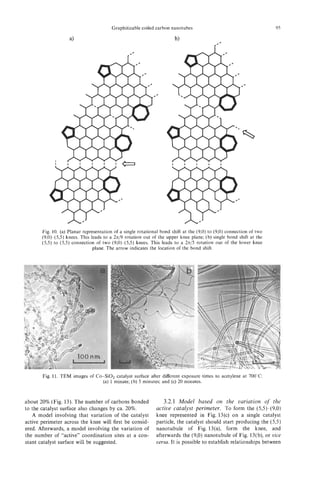
![96 A. FONSECAal.
et
Fig. 12. Explanation of the growth mechanism leading to tori (a)-(e) and to regular helices (a)-(h). (a)
Growing nanotubule on an immobilized catalyst particle; (b) the tube reaches obstacle A, (c) elastic
bending of the growing tubule caused by its blockage at the obstacle A; (d) after the formation of the
knee, a second growing stage can occur; (e) second blockage of the growing nanotubule by the obstacle
A, ( f ) after the formation of the second knee, a new growing stage can occur; (g) the tube reaches obstacle
B (h) formation of the regular helicity in the growing tubules by the obstacle B.
i Perimeter=15ak
Fig. 13. Model of the growth of a nanotubule “bonded” to the catalyst surface. (a) Growth of a straight
( 5 3 ) nanotubule on a catalyst particle, with perimeter 15ak; (b) growth of a straight (9,O) nanotubule on
a catalyst particle whose perimeter is 18ak (k is a constant and the grey ellipsoids of (a) and (b) represent
catalyst particles, the perimeters of which are equal to 15ak and 18ak, respectively); (c) (5,5)-(9,O) knee,
the two sides should grow optimally on catalyst particles having perimeters differing by ca. 20%.
the catalyst particle perimeter and the nature of the - If the active perimeter of the catalyst particle has a
tubules produced: dimension between 15nak and 18nak, - i.e.
15nak < active perimeter < 18nak - the two differ-
- When the active perimeter of the catalyst particle ent tubules can still be produced, but under stress.
matches perfectly the values 15nak or 18nak (where - The production of heptagon-pentagon pairs
n is the layer order, a is the side of the hexagon in among these hexagonal tubular structures leads to
graphite and k is a constant), the corresponding the formation of regular or tightly wound helices.
straight nanotubules (5n,5n) or (9n,O) will be pro- Each knee provides a switch between the tubule
duced, respectively [Fig. 13(a) and (b)] . formation of Fig. 13(a) and (b) [Fig. 13(c)].](https://image.slidesharecdn.com/13709313-carbon-nanotubes-120928071547-phpapp01/85/13709313-carbon-nanotubes-109-320.jpg)
![Graphitizable coiled carbon nanotubes 97
According to Amelinckx et al.[9], this switch could
be a consequence of the rotation of an ovoid
catalyst particle. However, from this model, during
the production of the parallel hexagons, a complete
“catalyst-tubule bonds rearrangement” must occur
after each hexagonal layer is produced. Otherwise,
as seen from the translation of the catalyst particle
in a direction perpendicular to its median plane,
the catalyst would get completely out of the
growing tubule. Since a mechanism involving this
“catalyst-tubule bonds rearrangement” is not very
likely, we shall now try to explain the growth of
a coiled tubule using a model based on the
variation of the number of active coordination
sites at a constant catalyst surface by a model
which does not involve “catalyst-tubule bonds
rearrangement”.
3.2.2 Model based on the variation o thef
number o “active” coordination sites at the cata-
f
lyst surface. The growth of tubules during the
decomposition of acetylene can be explained in three
steps, which are the decomposition of acetylene, the
initiation reaction and the propagation reaction. This
is illustrated in Fig. 14 by the model of a (5,5) tubule
growing on a catalyst particle:
--.
- First, dehydrogenative bonding of acetylene to the
catalyst surface will free hydrogen and produce C2
moieties bonded to the catalyst coordination sites.
These C, units are assumed to be the building
blocks for the tubules. C,H2 flow
- Secondly, at an initial stage, the first layer of C,
units diffusing out of the catalyst remains at a Van Fig. 14. Schematic representation of a ( 5 , s ) tubule growing
on the corresponding catalyst particle. The decomposition
der Waals distance from the C2 layer coordinated of acetylene on the same catalyst particle is also represented.
to the catalyst surface. Then, if the C, units of that The catalyst contains many active sites but only those
outer layer bind to one another, this will lead to a symbolized by grey circles are directly involved in the ( 5 , s )
half fullerene. Depending on whether the central tubule growth.
axis of that half fullerene is a threefold or a fivefold
rotation axis, a (9n,0) or a (5n,5n) tubule will start
growing, respectively. The half fullerene can also 3.2.2.1 Growth mechanism of a (5n,5n)
grow to completion instead of starting a nanotu- tubule, over 20n coordination sites o the catalyst.
f
bule[17]. This assumption is reinforced by the fact The growth of a general (5n,5n) tubule on the catalyst
that we have detected, by HPLC and mass spec- surface is illustrated by that of the (5,5) tubule in
trometry, the presence of fullerenes C,,, C,,, ... Figs 14 and 15. The external circles of the Schlegel
CIg6in the toluene extract of the crude nanotubules diagrams in Fig. 15(a)-(c) represent half c0 cut at
6
produced by the catalytic decomposition of the equatorial plane perpendicular to its fivefold
acetylene. rotational symmetry axis or the end of a (5,5) tubule.
- Third, the C2 units are inserted between the catalyst The equatorial carbons bearing a vacant bond are
coordination sites and the growing nanotubule bonded to the catalyst coordinatively [Fig. 15(a)
(Fig. 14). The last C2 unit introduced will still be and (a’)].
bonded to the catalyst coordination sites. From For the sake of clarity, ten coordination sites are
the catalyst surface, a new C, unit will again drawn a little further away from the surface of the
displace the previous one, which becomes part of particle in Fig. 15(a)-(c). These sites are real surface
the growing tubule, and so on. sites and the formal link is shown by a solid line. In
this way the different C, units are easily distinguished
We shall now attempt to explain, from the chemi- in the figure and the formation of six-membered
cal bond point of view, the propagation reaction at rings is obvious. The planar tubule representations
the basis of tubule growth. A growth mechanism for of Fig. 15(a‘)-(c’) are equivalent to those in
the (5n,5n) tubule, the (9n,0) tubule and the Fig. 15(a)-(c), respectively. The former figures allow
(9n,0)-( 5n,5n) knee, which are the three fundamental a better understanding of tubule growth. Arriving C2
tubule building blocks, is also suggested. units are first coordinated to the catalyst coordination](https://image.slidesharecdn.com/13709313-carbon-nanotubes-120928071547-phpapp01/85/13709313-carbon-nanotubes-110-320.jpg)
![98 A. FONSECAal.
et
Fig. 15. Growth of a (5n,5n) tubule on the catalyst surface, illustrated by that of the (5,5) tubule. The
central grey circle represents the catalyst particle with 10 coordination sites, and the small grey circles
represent the other 10 catalyst coordination sites. The normal and bold lines represent single and double
bonds, respectively, while coordinative bonds are represented by dotted lines [(a), (b) and (c)]; (a'), ( b )
and (c') are the corresponding planar representations.
sites already coordinated to the growing tubule and, Further arriving C2 units will behave as the latter
finally, they are inserted between the tubule and the one did, and so on [Fig. 15(c) and (c')].
catalyst coordination sites Fig. 15(b) and (b)]. This From Fig. 15, it can be seen that 20 coordination
leads to the formation of the first additional crown sites of the catalyst are involved in the growth of the
of perpendicular six membered rings to the growing (5,5) tubule, and in general, 20n coordination sites
tubule. In this growing structure, the C2 units arrive will be involved in the growth of the ( 5 4 5 4 tubule.
and are inserted perpendicularly to the tubule axis. It is obvious that the related catalyst particle must](https://image.slidesharecdn.com/13709313-carbon-nanotubes-120928071547-phpapp01/85/13709313-carbon-nanotubes-111-320.jpg)
![Graphitizable coiled carbon nanotubes 99
have more than the 20 coordination sites used, at As can be seen from Fig. 16, 24 coordination sites
least for the decomposition of acetylene. of the catalyst are involved in the growth of the (9,O)
3.2.2.2 Growth mechanism o a (9n,0) tubule,
f tubule and, in general, 24n coordination sites will be
over 24n coordination sites o the catalyst. The
f involved in the growth of the (9n,0) tubule.
growth of a general (9n,O) tubule on the catalyst 3.2.2.3 Growth mechanism o a (9n,0)-
f
surface is illustrated by that of the (9,O) tubule in (5n,5n) knee, involtiing from ,7411 20n coordi-
to
Fig. 16 which shows the "unsaturated" end of a (9,O) nation sites of the catalyst. Across the knee, the
tubule in a planar representation. At that end, the growth of the tubule starts as explained for the (9n,0)
carbons bearing a vacant bond are coordinatively tubule (Fig. 16) and must end as explained for the
bonded to the catalyst (grey circles) or to a growing (5n,5n) tubule (Fig. 15) or eice versa.
cis-polyacetylene chain (oblique bold lines in Fig. 16). As a starting point, a growing (9,O) tubule on the
The vacant bonds of the six cis-polyacetylene chains catalyst surface is illustrated in Fig. 17(a). In that
involved are taken to be coordinatively bonded to growing structure, the C, units arrive and are inserted
the catalyst [Fig. 16(b)]. These polyacetylene chains parallel to the tubule axis. If there is enough space~
are continuously extruded from the catalyst particle probably thanks to the distortion caused by the
where they are formed by polymerization of C2 units elastic folding of the growing tubule [Fig. 12(b)] -
assisted by the catalyst coordination sites. Note that two carbons (1") can be inserted instead of one
in order to reduce the number of representations of between a pair of coordination sites [Fig. 17(b)]. The
important steps, Fig. 16(b)includes nine new C2 units knee is started by the arrival of a C, unit perpendicu-
with respect to Fig. 16(a). lar to the tubule axis, each carbon of which has a
The 12 catalyst coordination sites -drawn further vacant bond for coordination. These two carbons
away from the surface of the particle (closer to the (instead of the carbon with two vacant bonds usually
tubule) - are acting in pairs, each pair being always involved) displace one carbon from a pair of coordi-
coordinatively bonded to one carbon of an inserted nation sites. This perpendicular C, unit constitutes
(1") or of a to-be-inserted (2") C, unit and to two the basis of the future seven-membered ring. Note
other carbons which are members of two neighbour- again that nine new C, units are shown in Fig. 17(b)
ing cis-polyacetylene chains (3"). It should be empha- as compared with Fig. 17(a).
sized that, as against the (5n,5n) tubule growth, the Among the three C, units arriving together, two
C, units extruded from the catalyst particle are are parallel to the tubule axis (2') and one is ortho-
positioned in this case parallel to the tubule axis gonal to the tubule axis [I" in Fig. 17(b)]. First, only
before their jnsertion. the parallel units are inserted into the tubule structure
Two coordinative bonds of two neighbouring cis- [Fig. 17(c)]. These two inserted C, units (2') were
polyacetylene chains of the growing tubule are speci- displaced by the arrival of two orthogonal C, units
fically displaced from a pair of catalyst coordination (3") and all further arriving C, units will be ortho-
sites by the insertion of one carbon of a C2 unit [2" gonal to the tubule axis.
in Fig. 16(b)]. The second carbon of that C, unit is Meanwhile, the coordinative bonding of the two
still1 bonded to the pair of coordination sites. It will C2 units within the pairs of coordinative sites forces
later be displaced from that pair of coordination sites the occupied sites to spread. As a result, in the
by the srrival of the next two C, segments of the two direction opposite to the place where the first ortho-
growing cis-polyacetylene chains considered [3" in gonal C , unit arrived, there is only enough room for
Fig. 16(c)]. The C, unit and cis-polyacetylene C2 a single site (") instead of for a pair of sites
segments are hence inserted into the growing tubule. [Fig. 17(c)]. That site now coordinates the two cis-
The further arriving C, units or cis-polyacetylene C2 polyacetylene C , segments, but without the possibility
segments will act as the latter one did, and so on of inserting a new C, unit. The displacement of that
[Fig. 16(c)]. site from the growing nanotubule leads to the closure
I I
I 10
I
I
I
I
t
I
1 I
I I
I I
Fig. 16. Growth of a (9n,O) tubule on the catalyst surface illustrated by that of the (9,O) tubule. The
normal and bold lines represent single and double bonds, respectively.](https://image.slidesharecdn.com/13709313-carbon-nanotubes-120928071547-phpapp01/85/13709313-carbon-nanotubes-112-320.jpg)
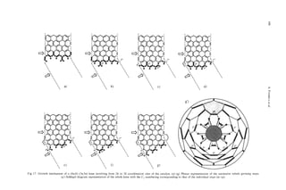
![Graphitizable coiled carbon nanotubes 101
of the five-membered ring [Fig. 17(d)]. Note also in Fig. 18(f)] leads to positioning of the seven-
that only six new C, units are shown in Fig. 17(c) membered ring. The closure of that ring, during a
with respect to Fig. 17(b). normal (9n,O) tubule growing step [Fig. 19(g) and
Once the pair of sites is disconnected from the (g')], completes the knee and the following steps will
growing tubule [Fig. 17(d)], an orthogonal C2 unit be the growth of the (9n,O) tubule proceeding as
is inserted below the five membered ring [4" in explained in Fig. 16. Figure 18(g') is a Schlegel
Fig. 17(e)]. The latter inserted C2unit and the remain- diagram of the (5,5)-(9,O) knee, equivalent to Fig.
ing two cis-polyacetylene C2 segments are finally 18(g). In that diagram it is possible to identify the
displaced by the arrival two orthogonal C2 units C, units introduced at the different growing steps
[Y in Fig. 18(f)]. [Fig. lS(a)-(g)] by their numbering.
The carbon atoms linked to the remaining twenty An important conclusion obtained from the model
coordination sites have now finished to rearrange to based on the variation of the number of coordination
a fivefold symmetry [Fig. 17(f)]. Consecutive inser- sites at the catalyst surface is that all double bonds
tion of the five orthogonal C2 units [lo,3" and 5") can be localized on the (9n,0)-(5n,5n) knee and
displaced from the catalyst by the arrival of five new connected nanotubes. In fact, in that model, only
Orthogonal C, units closes the seven-membered ring single C-C bonds are formed and there is no double
and completes the knee [Fig. 17(g) and (g')]. Further bond formation during the nanotubule growth. All
growth will yield a (5n,5n) tubule. It will proceed of the double bonds are already localized on the C,
as already explained in Fig. 15. Figure 17(g') is a units or on the inserted cis-polyacetylene chains. As
Schlegel diagram explanation of the (9,O)-( 5,5) knee, seen from Figs 17 and 18, there is no double bond
equivalent to Fig. 17(g). In that diagram it is possible on the sides of the five membered ring and there is
to identify the C, units introduced at the different only one double bond on the seven membered ring.
steps [Fig. 17(a)-(g)] by their numbering. It should also be pointed out that localizing the
3.2.2.4 Growth mechanism of a (5n,5n)- double bonds on the (9n,0)-(5n,5n) knee and con-
( 9 ~ 0 knee, involving from 20n to 24n coordina- nected tubules was a very difficult task before the
)
tion sites o the catalyst. The explanation given establishment of this model. Once the double bonds
f
here to pass from a (9n,0) tubule to a (5n,5n) tubule are localized, after replacing the vacant bonds of the
can also be used backwards to pass from a (5n,5n) (9n,0)-( 5n,5n) knee of Fig. 17(g') by hydrogens, it is
tubule to a (9n,O) tubule. The progressive steps are possible to have a three dimensional view of the knee
illustrated in Fig. 18. The starting point of the knee (Fig. 19). The introduction of the parameters of
is again the blockage of tubule growth at the seven- Fig. 19 into a more sophisticated program can also
membered ring [1"in Fig. lX(a)J. The later formation be used in order to minimize the energy and simulate
of the five-membered ring is only a consequence of the real knee angle[18,19].
tubule growth blockage at the seven-membered ring. Concerning the multi-shell tubules, the graphitic
Secondly, probably because of the large space created layers of the growing nanotubule described are sup-
on the other side of the tubule by the elastic bending posed to grow on the same catalyst particle, at the
[Fig. 12(b)] after tubule blockage, a cis-butadiene same time as the inner layer does. This is in agreement
[2" in Fig. 18(b)] can be inserted instead of the usual with the observations of Fig. 11, where it is possible
orthogonal 6,units. This cis-butadiene arriving with to see that the diameter range of the young tubes (1
four new coordination sites [black points on minute) is about the same as that of the old ones (20
Fig. 18(b)] will be the head of two cis-polyacetylene minutes). Moreover, it has also been observed that
chains C3" in Fig. 18(c)]. (The freshly arrived C, during a long exposure time (5 hours) of the tubules
segments of the cis-polyacetylene chain, not yet to the reaction conditions, only amorphous carbon
inserted in the tubule, are represented by dotted lines is deposited on the outer layer[4,5], and no tubes
for the sake of clarity.) These two chains are started with larger diameters were observed.
at the five-membered ring [Fig. 18(e)]. The insertion As the diameter of the catalyst particle is supposed
of that cis-butadiene also disturbs the other coordina- to be close to that of the single-shell tubule[20], or
tion sites, so that four other cis-polyacetylene chains to that of the inner tubule[8], the number of graphitic
[4" and 5" in Fig. 18(c)] are also inserted into the layers might depend on the flow rate of acetylene at
growing tubule. The other logical growing steps of the catalyst particle. The graphitic layers are supposed
the (53-(9,O) knee are very close to the mechanism to be formed by the Cz units formed on the catalyst
explained for the (9n,0) tubule. The insertion of the particle, exceeding those needed for the growth of the
first cis-polyacetylene units [3" in Figs 18(c) and (d)] multi-shell tubule inner layer. This generalisation to
and the coordination of the first parallel C2units [6" multi-layer tubules is just a hypothesis, since we do
in Fig. 18(d)], followed by the insertion of the cis- not have any experimental proof yet.
polyacetylene units [4O in Figs 18(d) and (e)] and the
coordination of parallel C2 units [7" in Fig. 18(e)] 4. CONCLUSIONS
leads to positioning of the five membered ring. The
closure of that ring, followed by the insertion of the The building of knees, tori and helices is described
cis-polyacetylene units [5" and 8" in Figs 18(e) and bv a simple formalism.
(f)] and coordination of three parallel C, units [So Relationships are established between the tubules](https://image.slidesharecdn.com/13709313-carbon-nanotubes-120928071547-phpapp01/85/13709313-carbon-nanotubes-114-320.jpg)
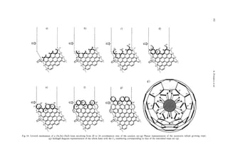
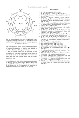

![HEMI-TOROIDAL NETWORKS IN PYROLYTIC
CARBON NANOTUBES
A. SARKAR, W. KROTO
H.
School of Chemistry and Molecular Science, University of Sussex, Brighton, BN1 9QJ U.K.
and
M. ENDO
Department of Engineering, Shinshu University, Nagano, Japan
(Received 26 May 1994; accepted in revised form 16 August 1994)
Abstract-Evidence for the formation of an archetypal hemi-toroidal link structure between adjacent
concentric walls in pyrolytic carbon nanotubes is presented. The observed and simulated TEM images for
such structures are in excellent agreement. This study suggests that double-walled carbon nanotubes, in
which the inner and outer tubes are linked by such hemi-toroidal seals, may be one viable way of over-
coming the reactivity at the graphene edges of open-ended tubes to engineer stable and useful graphene
nanostructures.
Key Words-Nanotubes, pyrolytic carbon nanotubes, hemi-toroidal nanostructures.
1 INTRODUCTION
. During the course of a detailed study of the struc-
The discovery by Iijima[ 11 that carbon nanotubes ture and growth of pyrolyticcarbon nanotubes (F'CNTs)
form in a Kratschmer-Huffman fullerene generator[2], we have found that complex graphitisation processes
and the subsequent development of techniques by occur during a second stage of heat treatment of these
Ebbeson and Ajayan[3] and others to produce them materials[20,21]. In particular, we here draw attention
in viable quantities, promise to have important impli- to evidence that hemi-toroidal graphite surfaces occur
cations for future nanotechnology. The tubes are es- regularly during nanotube production. In this commu-
sentially elongated fuIlerenes[4] and, thus, description nication we present evidence for the formation of single-
(in particular structural characterisation) in terms of layered hemi-toroid structures, within bulk multi-walled
fullerene chemistry/physics principles is appropriate material during PCNT graphitisation. The structures
and useful. A growth mechanism has been proposed occur in material prepared by pyrolysis of hydrocar-
for the primary tube growth phase[4] which involves bons at ca. 1000°C and subjected to secondary heat
ingestion of carbon fragments (e.g., atoms and chain treatment at 2800°C. The structures have been studied
molecules) at the reactive hemi-fuuerene closed end- experimentally by high resolution transmission electror,
caps of the tubes. An open-ended growth mechanism microscopy (HRTEM)[20] and the resulting images
has also been proposed[5]. A closed-end growth mech- compared with simulations. The simulated structures
anism is consistent with the--observations of Ulmer were generated from hypothetica1 fullerene related
et a . and McElvany et al. [7], that fullerenes can
l [6] hemi-toroidal networks, which were constructed on
grow by ingestion of carbon fragments into their com- the basis of feasible graphene topologies relaxed by
pletely closed networks. Both growth schemes also are molecular mechanics. During the course of the present
consistent with Iijima's observation that, in general, study of PCNTs, Iijima et al. [5] have obtained TEM
the tubes appear to have their hexagons helically dis- images showing related structures in arc-formed car-
posed in the tube walIs[l]. bon nanotubes (ACNTs).
The discovery that carbon generates closed-cage
fullerenes spontaneousIy[2,8] as well as nanotubes[l,3] 2. OBSERVATIONS
has stimulated the question of whether other topolog-
ically accessible networks are feasible. Predictions on The PCNTs obtained by decomposition of benzene
the possibility of both small fullerenes[9] and giant ful- at ca. 1000-1070°C on a ceramic substrate were gath-
lerenes[lQ,ll] appear to have been vindicated[l2,13]. ered using a toothpick and heat treated at a tempera-
As well as general closed-cage structures, extended ture of 2800°C for 15 minutes[21]. The heat-treated
repeat-pattern networks involving seven- and other- PCNTs were then mounted on a porous amorphous
membered rings have been considered by Terrones and carbon electron microscope grid (so-called carbon
MacKay[l4,l5] and Lenosky et al.1161. Other struc- ultra-microgrid). HRTEM observations were made
tures have been considered and, in particular, Cher- using a LaB6 filament operating at an accelerating
nozatonskii[l.7] and Ihara et a1.[18,19] have discussed voltage of 300 kV. The special aberration coefficient
toroidal structure. C , = 2.0 mm and lambda = 0.0197 A. The under-focus
105](https://image.slidesharecdn.com/13709313-carbon-nanotubes-120928071547-phpapp01/85/13709313-carbon-nanotubes-118-320.jpg)
![106 et
A. SARKAR al.
value was chosen deltaf = 65 nm, where the sin(x) ary growth showed no regular structure in the HRTEM
transfer function has a large plateau at sin(x) ca. -1 images (Fig. l), suggesting that it might consist largely
against the interlayer spacing of carbon in the range of some form of “amorphous” carbon. After the sec-
5.0-2.8 A. These conditions were optimum for observ- ond stage of heat treatment, at 28OO0C, the amor-
ing high-contrast 002 lattice fringes form the PCNTs. phous sheaths graphitise to a very large degree,
The simulations were carried out on a Silicon producing multi-walled graphite nanotubes which tend
Graphics Iris Indigo workstation using the CERIUS to be sealed off at points where the spindle-like for-
molecular modeling and the associated HRTEM mod- mations are thinnest. The sealed-off end region of one
ule. The multislice simulation technique was applied such PCNT is shown in Fig. 1.
using the following parameters: electron energy 400 The detailed analysis of the way in which the over-
kV (lambda = 0.016 A); C, (aberration coefficient) = all and internal structure of PCNTs apparently arise
2.7 mm; focus value deltaf = 66 nm; beam spread = is discussed elsewhere[20]. Here, we draw attention to
0.30 mrad. some particularly interesting and unusual structures
In Fig. 1 is shown a HRTEM image of part of which occur in the body of the nanotubes. An expan-
the end of a PCNT. The initial material consisted of sion of the section of the central core which lies ca. f
carbon nanotubes upon which bi-conical spindle-like below the tip of the nanotube in Fig. 1 is shown in
secondary growth had deposited[21], apparently by in- Fig. 2. Loop structures occur at points a-d and a‘-d‘
homogeneous deposition of aromatic carbonaceous, in the walls in directly opposing pairs. This parallel be-
presumably disordered, layers on the primary substrate haviour must, on the basis of statistical arguments, be
nanotube. Prior to further heat treatment, the second- related and we interpret the patterns as evidence for
a hemi-toroidal connection between the inner and
outer adjacent concentric graphene tubes (Le., turn-
overs similar to a rolled-over sock). That the loops,
seen in the HRTEM, are evidence for very narrow
single-walled closed-ended tubes trapped within the
walls can be discounted, also on statistical grounds.
Perhaps the most important features in the images
are the dark line images that interconnect adjacent
loops. We particularly draw attention to the structure
b-b‘ in the expanded image in Fig. 2. Here, the adja-
cent loops are fairly distinct and well matched on ei-
Fig. 2. Expanded image of part of the annealed PCNT of
Fig. 1 showing several regions (a/a’-d/d‘), in detail, where
complex looped images appear to be associated with graph-
ite turnover structures. The clearest eliptical image can be
Fig. 1 . The sealed-off tip of an annealed PCNT seen between markers b and b’.](https://image.slidesharecdn.com/13709313-carbon-nanotubes-120928071547-phpapp01/85/13709313-carbon-nanotubes-119-320.jpg)
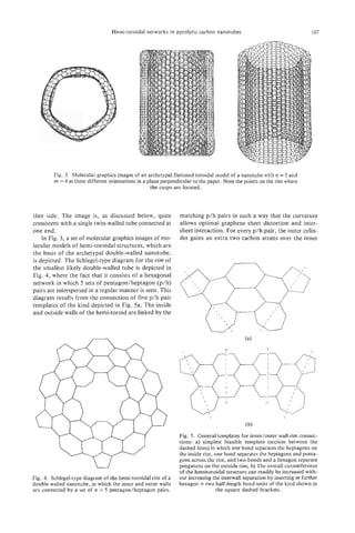
![I08 et
A. SARKAR al.
one. The number of p/h pairs determines the wall sep- workstation operating the Cerius Molecular Mechan-
aration and, for five such pairs, the circumference of ics Programme. The results, at a series of angles (0, 5,
the outer wall gains 10 extra atoms and the difference 10, and 15') to the normal in a plane perpendicular to
in the radius increases by ca. 3.5 A-very close to the the paper, are shown diagrammatically in Fig. 6a. The
optimum graphite interlayer spacing. Furthermore, if associated simulated TEM images for the analogous
a particular template is bisected and further hexago- angles to the electron beam are depicted in Fig. 6b.
nal network inserted at the dashed line, as indicated The model has inner/outer radii of ca. 1.75/2.10 nm
in Fig. 5 , then the radii of the connected concentric (Le., 5 x and 6 x the diameter of waist of C7,J. The
cylinders are easily increased without increasing the structure depicted in the experimentally observed
interwall spacing, which will remain approximately HRTEM image is ca. 3.50/3.85 (Le., ca. l o x and l l x
0.35 nm, as required for graphite. A structure results c70)*
such as that shown in Fig. 3. These templates gener- As the tube orientation changes, we note that the
ate non-helical structures; however, modified versions interference pattern associated with the rim changes
readily generate helical forms of the kind observed[24]. from a line to an ellipse and the loop structures at the
There is, of course, yet another degree of freedom in apices remain quite distinct. The oval patterns in the
this simple template pattern, which involves splitting observed (Fig. 2) and simulated (Fig. 6) HRTEM im-
the template along an arc connecting the midpoints of ages are perfectly consistent with one another. For this
the bonds between the h/p pairs. This procedure results preliminary investigation, a symmetric wall configu-
in larger inter-wall spacings[24]; the resulting struc- ration was used for simplicity. Hemi-toroid connec-
tures are not considered here. tion of inner and outer tubes with helical structured
We note that in the HRTEM images (Figs. 1 and 2) walls requires somewhat more complicated disposi-
the points b and b' lie at the apices of the long axis of tions of 5/6/7 rings in the lip region[24]. The general
an elliptical line-like image. Our study suggests that validity of the conclusions drawn here is, however, not
this pattern is the HRTEM fingerprint of a hemi- affected. Initial studies of this problem[24] indicate
toroidal link structure joining two concentric graph- that linking between the inner and outer walls is also
ite cylinders, whose radii differ by the graphite not hindered in general.
interlayers separation (ca. 0.35 nm). If the number of The toroids show an interesting change in overall
p/h pairs, n = 5 and the number of insertions m = 4 morphology as they become larger, at least at the
(according to Fig. 4), then the structure shown in Fig. 3 1ip.The hypothetical small toroid shown in Fig. 3a is
is generated. The basic topologically generated struc- actually quite smooth and essentially a fairly rounded
ture was relaxed interactively using a Silicon Graphics structure. As the structures become larger, the strain
- -
I
i
Fig. 6. above) Molecular graphics images of an archetypal flattened toroidal model of a nanotube with
n = 5 and rn = 4 at three different orientations ( 0 , 5 , 10, 15") in a plane perpendicular to the paper. below)
Resulting simulated TEM images of the nanotube at the above orientations to the electron beam; note that
even the spring onion-like bulges at the ends are reproduced.](https://image.slidesharecdn.com/13709313-carbon-nanotubes-120928071547-phpapp01/85/13709313-carbon-nanotubes-121-320.jpg)
![Hemi-toroidal networks in pyrolytic carbon nanotubes 109
becomes focused in the regions where the pentagons are unlikely to form very often under the conditions
and heptagons lie, producing localised cusps and sad- discussed here. However, the present results do sug-
dle points that can be seen relatively clearly in Fig. 3. gest that, in the future, nanoscale engineering tech-
Fascinating toroidal structures with Dohand Dndsym- niques may be developed in which the graphene edges
metry are produced, depending on whether the p/h of open-ended double-walled tubes, produced by con-
pairs at opposite ends of the tube are directly aligned trolled oxidation or otherwise, may be cauterised by
o are offset by 27r/2n. In Fig. 3 the symmetry is DSh.
r rim-seals which link the inner and outer tubes; this
Chiral structures are produced by off-setting the pent- may be one viable way of overcoming any dangling
agon from the heptagons[24]. In a D5dstructure, the bond reactivity that would otherwise preclude the use
walls are fluted between heptagons at opposite ends of these structures in nanoscale devices. In this way,
of the inner tube and the pentagons of the outer walls. a long (or high) fully toroidal structure might be
It is interesting to note that, in the computer images, formed.
the cusps give rise to variations in the smoothness of
the more-or-less elliptical image generated by the rim
Acknowledgement-We thank Raz Abeysinghe, Lawrence
when viewed at an angle. The observed image (b-b’) Dunne, Thomas Ebbeson, Mauricio Terrones, and David
exhibits variations consistent with the localised cusp- Walton for their help. We are also grateful to the SERC and
ing that our model predicts will occur. the Royal Society for financial support.
3. DISCUSSION REFERENCES
In this study, we note that epitaxial graphitisation
is achieved by heat treatment of the apparently mainly 1. S. Iijima, Nature 354, 56 (1991).
amorphous material which surrounds a nanotube[20]. 2. W . Kratschmer, L. Lamb, K. Fostiropoulos, and D.
Huffman, Nature 347, 354 (1990).
As well as bulk graphitisation, localised hemi-toroidal 3. T. W. Ebbeson and P. M. Ajayan, Nature 358, 220
structures that connect adjacent walls appear to form (1992).
readily. This type of structure may be important as it 4. M. Endo and H. W. Kroto, L Phys. Chem. 96, 6941
suggests that double-walled, closed structures may be ( 1992).
5. S. Iijima, P. M. Ajayan, and T. Ichihashi, Phys. Rev.
produced by heat treatment, so forming stable nano- Letts. 69, 3100 (1992).
scale graphite tubes in which dangling bonds have 6 . G. Ulmer, E. E. B. Cambell, R. Kuhnle, H-G. Busmann,
been eliminated. It wl be most interesting to probe
il and I. V. Hertel, Chem. Phys. Letts. 182, 114 (1991).
the relative reactivity of these structures for the future 7. S. W . McElvany, M. M. Ross, N. S. Goroff, and E
Diederich, Science 259, 1594 (1993).
of nanoscale devices, such as quantum wire supports.
8. H. W. Kroto, J. R. Heath, S. C. O’Brien, R. E Curl, and
Although the curvatures of the rims appear to be quite R. E. Smalley, Nature 354, 359 (1985).
tight, it is clear from the loop images that the occur- 9. H. W. Kroto, Nature 329, 529 (1977).
rence of turnovers between concentric cylinders with 10. H. W. Kroto and K. G . McKay, Nature 331, 328 (1988).
a gap spacing of the standard graphite interlayer spac- 1 1 . H. W. Kroto, Chem. Brit. 26, 40 (1990).
12. T. Guo, M. D. Diener, Y. Chai, M. J. Alford, R. E.
ing is relatively common. Interestingly, the edges of Haufler, S. M. McClure, T. Ohno, J. H. Weaver, G . E.
the rims appear to be readily visible and this has al- Scuseria, and R. E. Smalley, Science 257, 1661 (1992).
lowed us to confirm the relationship between oppos- 13. L. D. Lamb, D. R. Huffman, R. K. Workman, S. How-
ing loops. Bulges in the loops of the kind observed at ells, T. Chen, D. Sarid, and R. F. Ziolo, Science 255,
d’ in Fig. 2 are simulated theoretically as indicated in 1413 (1991).
14. H. Terrones and A. L. Mackay, In The Fuilerenes (Ed-
Fig. 6 . ited by H. W. Kroto, J. E. Fischer, and D. E. Cox), pp.
During the course of the study on the simplest ar- 113-122. Pergamon, Oxford (1993).
chetypal twin-walled structures in PCNT material de- 15. A. L. Mackay and H. Terrones, In TheFullerenes (Ed-
scribed here, the observation of Iijima et al.[5] on ited by H. W. Kroto and D. R. M. Walton), Cambridge
University Press (1993).
related multi-walled hemi-toroidal structures in ACNTs 16. T. Lenosky, X. Gonze, M. P. Teter, and V. Elser, Na-
appeared. It will be most interesting to probe the dif- ture 355, 333 (1992).
ferences in the formation process involved. 17. L. A. Chernozatonskii, Phys. Letts. A . 170, 37 (1992).
The question might be addressed as to whether the 18. S. Ihara, S. Itoh, and Y. Kitakami, Phys. Rev. B 47,
13908 (1993).
hemispheroidal structures observed here may provide 19. S. Itoh, S. Ihara, and Y. Kitakami, Phys. Rev. B 47,
an indication that complete toroids may be formed 1703 (1993).
from graphite. The structures appear to form as a re- 20. A. Sarkar, H. W. Kroto, and M. Endo, in prep.
sult of optimal graphitisation of two adjacent concen- 21. M. Endo, K. Takeuchi, S. Igarishi, M. Shiraishi, and
tric graphene tubes, when further extension growth is H. W. Kroto, J. Phys. Chem. Solids 54, 1841 (1993).
22. S. Iijima, Phys. Rev. Letts. 21, 3100 (1992).
no longer feasible (Lea,as in the case shown in Fig. 2 23. S. Iijima, Mat. Sci. and Eng. B19, 172 (1993).
a t b-b‘ where a four-walled tube section must reduce 24. U. Heinen, H. W. Kroto, A. Sarkar, and M. Terrones,
to a two-walled one.) This suggests that perfect toroids in prep.](https://image.slidesharecdn.com/13709313-carbon-nanotubes-120928071547-phpapp01/85/13709313-carbon-nanotubes-122-320.jpg)

![PROPERTIES OF BUCKYTUBES AND DERIVATIVES
X. K. WANG,X. W. LIN, S. N. SONG, P. DRAVID, B. KETTERSON,
V. J.
and R. P. H. CHANG*
Materials Research Center, Northwestern University, Evanston, IL 60208, U.S.A.
(Received 25 July 1994; accepted 10 February 1995)
Abstract-The structural, magnetic, and transport properties of bundles of buckytubes (buckybundles)
have been studied. High-resolution electron microscopy (HREM) images have revealed the detailed struc-
tural properties and the growth pattern of buckytubes and their derivatives. The magnetic susceptibility
of a bulk sample of buckybundles is -10.75 x lop6 emu/g for the magnetic field parallel to the bundle
axes, which is approximately 1. I times the perpendicular value and 3 times larger than that of C,. The
0
magnetoresistance (MR) and Hall coefficient measurements on the buckybundles show a negative MR at
low temperature and a positive MR at a temperature above 60 K and a nearly linear increase in conduc-
tivity with temperature. The results show that a buckybundle may best be described as a semimetal. Using
a stable glow discharge, buckybundles with remarkably large diameters (up to 200 pm) have been synthe-
sized. These bundles are evenly spaced, parallel, and occupy the entire central region of a deposited rod.
HREM images revealed higher yield and improved quality buckytubes produced by this technique com-
pared to those produced by a conventional arc discharge.
Key Words-Buckytubes, buckybundle, glow discharge, magnetic properties, transport properties.
1. INTRODUCTION the range of 3000 K to 4000 K. [ l l ] After arcing for an
hour, a deposited carbon rod 165 mm in length and
Since the initial discovery[l,2] and subsequent devel-
16 mm in diameter was built up on the end of the cath-
opment of large-scale synthesis of buckytubes[3], var-
ode. The deposition rate was 46 pm/sec.
ious methods for their synthesis, characterization, and
potential applications have been pursued[4-121. Par-
2.2 Structural measurements by
allel to these experimental efforts, theoreticians have
electroIt r icroscopy
n
predicted that buckytubes may exhibit a variation in
Most of the HREM observations were made by
their electronic structure ranging from metallic to
scraping the transition region between the “black ring”
semiconducting, depending on the diameter of the
material and the outer shell, and then dispersing the
tubes and the degree of helical arrangement[l3-161.
powder onto a holey carbon TEM grid. Additional ex-
Thus, careful characterization of buckytubes and their
periments were conducted by preparing cross-sections
derivatives is essential for understanding the electronic
of the rod, such that the rod was electron-transparent
properties of buckytubes.
and roughly parallel to the electron beam. HREM ob-
In this article, we describe and summarize our stud-
servations were performed using an HF-2000 TEM,
ies on the structural, magnetic,and transport proper-
equipped with a cold field emission gun (c FEG) op-
ties of buckytubes. In addition, we describe how a
erated at 200 keV, an Oxford Pentafet X-ray detector,
conventional arc discharge can be modified into a sta-
and a Gatan 666 parallel EELS spectrometer.
ble glow discharge for the efficient synthesis of well-
aligned buckytubes.
2.3 Magnetic susceptibility measurements
Magnetic susceptibility measurements were per-
2. EXPERIMENTAL formed using a magnetic property measurement sys-
tem (Quantum Designs Model MPMS). This system
2.1 Synthesis of buckytubes has a differential sensitivity of emu in magnetic
Bundles of buckytubes were grown, based on an fields ranging from -5.5 T to +5.5 T over a tem-
arc method similar to that of Ebbesen and Ajayan[3]. perature range of 1.9 K-400 K. The materiz$s studied
The arc was generated by a direct current (50-300 A, included: three buckybundle samples of 0.07 12 g,
10-30 V) in a He atmosphere at a pressure of 500 Torr. 0.0437 g, and 0.0346 g; 0.0490 g of C60 powder,
Two graphite electrode rods with different diameters 0.1100 g of gray-shell material, 0.1413 g of polycrys-
were employed. The feed rod (anode) was nominally talline graphite anode, and a 0.0416-g graphite single
12.7 mm in diameter and 305 mm long; the cathode crystal. Measurements were performed at temperatures
rod was 25.4 mm in diameter and 100 mm long (it re- from 2 K to 300 K and.in magnetic fields ranging from
mained largely uneroded as the feed rod was con- 0.005 T to 4 T. The susceptibility of buckytubes was
sumed). Typical rod temperature near the arc was in measured with the magnetic field (H) either parallel
to (x!) or perpendicular to (xk)the buckybundle
axis. All samples used in this work were enclosed in
*Author to whom correspondence should be addressed. gelatin capsules, and the background of the container
111](https://image.slidesharecdn.com/13709313-carbon-nanotubes-120928071547-phpapp01/85/13709313-carbon-nanotubes-124-320.jpg)
![112 X. K . WANGet al.
was subtracted from the data. The absolute accuracy
of the mass susceptibility relative to the “standard”
value of the graphite crystal was about 1070.
2.4 Transport property measurements
The transport properties were measured using stan-
dard dc (for the Hall effect) and ac (for MR) four-
terminal techniques. The instrument used in this study
was the same one we employed for the measurements
of magnetic properties. The contact configuration is
shown schematically by the inset in Fig. 6 (a). The I-V
characteristic was measured to ensure Ohmic behav-
ior so that no hot electron effects were present. The
magnetic field was applied perpendicular to the tube
axis. The measured MR and apparent Hall coefficient
showed essentially the same temperature and field de-
pendence, regardless of the samples used and the dis-
tance between the potential contacts, implying that the
samples were homogeneous. For example, the resid-
ual resistivity ratio, R(300 K)/R(5 K), measured on
different single buckybundles agreed with each other
within 1%.In what follows we present the data taken
on a single buckybundle having a diameter of 60 pm,
the distance between the two potential contacts being
350 pm.
Fig. 1 . (a) A cross-sectional TEM image of a bundle of
buckytubes; (b) an HREM image of a single bundle of bucky-
3. RESULTS AND DISCUSSIONS tubes with their axes parallel to the bundle axis.
3.1 Structural properties
Buckytubes were observed for the first time by has been suggested[l7] that the growth pattern, as well
HREM[ 1,2] and their structural properties were sub- as many properties of buckytubes, are intimately re-
sequently characterized. In this section, we will briefly lated to their helicacy. Here, we present the visible ob-
describe observations of the structure of a bundle of servations of frozen growth stage of buckytubes and
buckytubes, evidence for a helical growth of bucky- derivatives suggesting a helical growth mechanism.
tubes and their derivatives, and the single-shell Figure 2 shows two HREM images of buckytubes
structures. seen end-on (i.e., the axis of the tube being parallel
3.1.1 The structure of buckybundles. Both to the electron beam). The hollow center region is ap-
cross-sectional and high-resolution electron micros- parent, indicating the obvious tubular nature of the
copy images of a single bundle are shown in Fig. 1 (a) tubes. Strain contrast was evident in all these images,
(end-on-view) and 1 (b) (side view of a single bundle). which is reminiscent of disclination type defects[l8, 191.
The end-on view shows that the tubes are composed If we follow the individual inner-shell graphitic sheets
of concentric graphitic sheets. The spacing between the around, shown in Fig. 2 (a), we observe that the ter-
adjacent graphitic sheets is about 0.34 nm. The thin- mination is incomplete; that is, one extra graphitic
nest tube in this specimen, consisting of 8 carbon- sheet is associated with one portion of the inner shell
hexagon sheets, has an outside diameter of 8 nm. The compared with its opposite side. Figure 2 (b) shows
largest one, consisting of 48 sheets, has an outside di- that six graphitic sheets are seen to wrap around a
ameter of about 30 nm. It is worth noting that al- thicker buckytube. In other words, the tubes are more
though the tubes have a wide range of diameters, they of a rolled carpet geometry rather than the Russian
tend to be packed closely together. The side view of Doll-type structure in our sample.
the sing16 bundle directly reveals that the bundle con- We also observed that the rounded particulates in
sists of closely packed buckytubes running parallel to the transition region between the “black ring” and the
one another, these images clearly demonstrate that the outer shell of the deposited rod are a collection of
bundle is actually a bundle of buckytubes. Since the completely closed graphitic sheets with a helical pat-
valence requirements of all atoms in a buckytube (with tern of inner shells. Figure 3 shows a larger buckyfoot-
two sealed ends) are satisfied, the interaction among ball containing smaller inner footballs that seem to
buckytubes should be Van der Waals in nature. There- grow inside the larger one. The inner footballs clearly
fore, it is energetically favorable for buckytubes packed display extra unterminated graphitic sheets, indicative
closely together to form a “buckybundle.” of helical growth. These observations strongly suggest
3.1.2 The helicacy of buckytubes. The heli- that Fig. 3 represents buckyfootballs that form through
cacy of buckytubes is an interesting phenomenon. It a helical growth of the sheets analogous to that of](https://image.slidesharecdn.com/13709313-carbon-nanotubes-120928071547-phpapp01/85/13709313-carbon-nanotubes-125-320.jpg)
![Properties of buckytubes and derivatives 113
multilayer buckytubes. Because the insertion of pent-
agons and heptagons produced positive and negative
curvature of the hexagonal network, respectively, the
complicated morphologies of single-shell buckytubes
were probably a result of the insertion of pentagons,
heptagons, or various combinations into the single-
shell buckytube. We believe that it is much easier to in-
corporate pentagonal and heptagonal defects in these
single-shell structures than in multilayer buckytubes.
3.2 Magnetic properties
In the first paper reporting the observation of c60,
Kroto et al. suggested that the molecule was aromatic-
like with its inner and outer surfaces covered with a
“sea” of a-electrons[ 181. Accordingly, Cm should ex-
hibit a large diamagnetic susceptibility associated with
a a-electron ring current. This suggestion appeared to
be supported by NMR chemical shift measurements
[ 19,231. Theoretical calculations of the magnetic sus-
ceptibility of c 0 performed by various groups were
6
not consistent; some authors predicted a vanishingly
small diamagnetism[24-261 and others predicted strong
diamagnetism (as in an aromatic system)[27,28]. Sus-
ceptibility measurements on C60and C,o showed that
the value for C,,, was about twice that of c60, but
that both were very sma11[25,29]. Another theoretical
calculation by Ajiki & Ando[30] showed that the cal-
culated magnetic susceptibility for the magnetic field
perpendicular to the carbon nanotube axis was about
three orders of magnitude larger than the parallel
value. It is, then, of interest to extend the measure-
ments to buckytubes.
With the availability of bulk samples of carbon
nanotubes (bundles of buckytubes), a systematic study
of the magnetic properties became possible. A cylin-
drical bulk deposit, with a diameter of 10 mm, con-
sisting of an inner core and an outer cladding, was
Fig. 2. Two HREM images of frozen growth of buckytubes formed on the graphite cathode during the arc process.
seen end-on.
The outer cladding, a gray shell, was composed mainly
of amorphous carbon and buckydoughnuts[3 11. The
inner core, with a diameter of 8 mm, consisted of an
single-crystal growth through a screw dislocation array of rather evenly spaced, parallel, and closely
mechanism[2]. packed bundles approximately 50 micrometers in di-
3.1.3 The structure of single-shell bucky- ameter. HREM revealed that the buckybundles in our
tubes. Single-shell buckytubes were first synthesized best sample were comprised of buckytubes running
by Iijima and Ichihashi[20] and Bethune et al. [21]. parallel to one another[32]. A buckytube in each bun-
Unlike their reports, where the single-shell buckytubes dle could be pictured as a rolled-up graphitic sheet
were found on the chamber wall, we found a large with a diameter ranging from 8 A to 300 A and a
number of monolayer buckytubes in a deposited rod length of a few microns. The tube was capped by sur-
which built up on the cathode of the dc arc[22]. The faces involving 6 pentagons (per layer) on each
synthesis of the single-shell buckytubes used in this end[l,2]. The purity of the bulk sample was examined
study was similar to that described in the experimen- by energy dispersive X-ray analysis. No elements
tal section. However, instead of using a monolithic heavier than carbon were observed. The C60powder
graphite anode, we utilized a composite anode consist- was extracted from the soot formed in the same cham-
ing of copper rods inserted inside a graphite anode in ber employed for production of the buckytubes. The
a variety of ways. The single-shellbuckytubes assumed purity of the c 0 powder used in this study was bet-
6
a large variety of shapes (shown in Fig. 4), such as ter than 99% as examined by high-performance liq-
buckytents, buckydomes, and giant fullerenes, and uid chromatography.
much shorter tubes than in previous reports. Protru- The measured mass susceptibility values for bucky-
sions, indentations, and bending were quite common, bundle (both x and xi), C6,,, the gray-shell mate-
:
unlike the faceted or smooth-faceted morphologies of rial, the polycrystalline graphite anode, and the](https://image.slidesharecdn.com/13709313-carbon-nanotubes-120928071547-phpapp01/85/13709313-carbon-nanotubes-126-320.jpg)
![I14 X. K . WANCet al.
_- . I .
. .
. .
5'n m
.. , .
Fig. 3. Three small buckyfootballs appear to grow inside a large buckyfootball.
graphite crystal are shown in Table 1. The measured emu/g, which is near the literature value (implying the
mass susceptibility of -0.35 x emu/g for c 0 is
6 behaviors of the remtiining materials do not involve
consistent with the literature value[29], and is 30 times impurities arising from the source material). The mea-
smaller than that of buckytubes. The c 0 powder
6 sured susceptibility of the gray-shell material, which
shows the strongest magnetic field dependence of the consists of amorphous carbon mixed with fragments
susceptibility and does not exhibit diamagnetism un- of buckytubes and buckydoughnuts, is close to (but
til H is greater than 0.5 T; saturation is observed for larger than) that of the source rod.
fields greater than 3 T. The c0 results, involving a
6 The measured magnetic susceptibility of multilayer
very small diamagnetic susceptibility and a strong buckytubes for xkis approximately half x; of graph-
magnetic field dependence, appear to support the ite. This can be interpreted as follows. We recall that
Elser-Haddon result where a cancellation occurs be- crystalline graphite is a semimetal with a small band
tween the diamagnetic and paramagnetic contribu- overlap and a low density of carriers (lO-l8/cm3)[33,
tions[26]. The small measured susceptibilityof C sug-
, 341; the in-plane effective mass is small ( m* mo). -&
gests that if it (or possibly other fullerenes) is present The bending of the graphite planes necessary to form
as a contaminant in the buckybundle matrix (which is a buckytube changes the band parameters. The rele-
likely at some level) its contribution will be small. vant dimensionless parameter is the ratio a/R, where
From Table 1, we see that the measured suscepti- a (=3.4 A) is the lattice constant and R is the bucky-
bility of the polycrystalline graphite anode (used to tube radius. For R = 20 A,the shift is expected to
produce the fullerenes measured here) is 6.50 x alter the nature of the conductivity[l3-161. In our
buckybundle samples, most of material involves
A
buckytubes with R > 100 confirmed by statistical
analysis of TEM data, and we assume that the elec-
Table 1. Measured room-temperature susceptibilities
SusceDtibilitv
Material Symbol x emu/g
Buckybundle: axis parallel
I
to H XB -10.75
Buckybundle: axis
perpendicular to H -9.60
Gray-shell material - -7.60
Graphite: c-axis parallel to H xk -21.10
Graphite: c-axis perpendicular
to H Xc' -0.50
Fig. 4. Various morphologies of single-shell buckytubes.](https://image.slidesharecdn.com/13709313-carbon-nanotubes-120928071547-phpapp01/85/13709313-carbon-nanotubes-127-320.jpg)
![Properties of buckytubes and derivatives 115
tronic properties are close to those of a graphite plane. The above discussion ignores all paramagnetic ef-
The study of electron energy loss spectra (EELS) sup- fects including band paramagnetism. Evidence for a
ports this model[19]. We can identify three relevant Curie-like contribution is seen at low temperatures in
energy scales. First, the quantizing effect of the cylin- some of the curves displayed in Fig. 5 and could arise,
drical geometry involves an energy AE = h2/2mR2= in part, from paramagnetic impurities (see below).
0.7 x lop2 eV. Second, there is the Fermi energy Ei, The anisotropic susceptibility of buckytubes is gov-
which is 1.2 x lop2 eV. Third, there is the thermal en- erned by various geometrical and structural factors
ergy, which at room temperature (the highest temper- (such as the aspect ratio and degree of perfection of
ature studied) is about 2.5 x eV. We see that all its structure). In the direction perpendicular to the
three of these energy scales are of the same order. If buckybundle axis, we d o not expect xi to be larger
we consider a higher temperature, where the carriers than 0.5 x However, in the direction parallel to the
.
:
are Boltzmann particles (with a small inelastic mean buckybundle axis x: might be much larger for a high-
free path !,)> and the magnetic field (-tesla) is a quality sample of buckytubes, as discussed above. The
small perturbation on the particle motion, the mag- measured anisotropy factor in this work (approxi-
neric susceptibility would be due to small quantum mately 1.1 at room temperature and increasing with
corrections to the energy of the system. For this quasi- falling temperature) likely represents a value smaller
classical case., the quantizing action of the geometry than that achievable with a highly ordered structure.
is not important; the response of the system to the per- The small value may be caused by imperfectly aligned
turbation may be considered as a sum over small pla- buckytubes in the buckybundle.
quettes of the size I , . (This additivity is hidden by the The magnetic susceptibility data for buckytubes,
effect of a non-gauge-invariant formalism[35]; never- amorphous graphite, crystalline graphite, the gray-
theless, it is a general physical property, and the in- shell material, and C,, as a function of temperatures
elastic mean free path is the correlation radius of a are shown in Fig. 5. Paramagnetic upturns were ob-
local magnetization.) Therefore, at high temperatures served (for all of the curves) at temperatures lower
a buckytube with R > I, may be considered as a than 10 K. Amorphous graphite and C,, show no ob-
rolied-up graphitic sheet (or concentric tubes). We use servable temperature dependence at temperatures
this model to calculate the susceptibility, xk, for the ranging from 10 K to 300 K, whereas the buckytube
field perpendicular to the buckybundle axis. We write sample exhibits a large increase in diamagnetic suscep-
the susceptibility tensor of single crystal graphite as tibility with falling temperature.
A plot of xpl vs T for C6, was used to estimate a
Curie constant of 8.6 x lO-’/mole, which corre-
sponds to 1.7 x lo-* electron spins per carbon atom
in C,,. It is possible that the paramagnetic upturn is
caused by a small amount of 0, within the sample.
To examine this point, we sealed a Cs0 sample under
a vacuum of 2 x lo-’ Torr in a chamber located at
To obtain the magnetic susceptibility of a buckytube
for the magnetic field perpendicular to the buckybun-
dle axis, xk,
we have to average the magnetic energy
E = 0.5 xjJH, Hj over the cylindrical geometry of the
buckytube (over a plane containing the a and c axes):
dE = 0 . 5 [ ~H 2 cos2 a
& + (6H 2 sin2 a ]da (2)
or
E = O.5H2[x&cos2 a + x& sin2 a ]d a
= 0.5H2(0.5x& + 0.5xk); (3)
Thus
Because x& = 41x&, this argument predicts
Temperature (K)
xg 0.5~; (5)
Fig. 5 . Temperature dependence of the magnetic suscepti-
bilities measured in a magnetic field of 2 T: (a) C,, powder,
This is consistent with our experimental results, which (b) polycrystalline graphite anode, (c) gray-shell material, (d)
strongly Suggest the existence of delocalized buckybundle: axis perpendicular to H , and (e) buckybundle:
Discussion of (L can be found in reference[36]. axis parallel to H .](https://image.slidesharecdn.com/13709313-carbon-nanotubes-120928071547-phpapp01/85/13709313-carbon-nanotubes-128-320.jpg)
![116 X. K. WANCet al.
the center of a quartz tube (holder). No susceptibil- the MR is negative at low fields followed by an upturn
ity difference between the c0 sealed in vacuum and
6 at another characteristic field that depends on temper-
unsealed samples was observed. Cm is a large band- ature. Our low-temperature MR data has two striking
gap (1.4 eV) semiconductor[29,37], and the paramag- features. First, at low temperatures and low fields
netic upturn at very low temperature is probably due A p / p o depends logarithmically on temperature and
to a very small concentration of foreign paramagnetic Bright’s model predicts a VTdependence at low fields.
impurities. Clearly, the data cannot be described by 1D WL
We conclude this section stating that buckytubes in theory. Second, from Fig. 6 (b), we see that the char-
a bundle have a large diamagnetic susceptibility for H acteristic magnetic field at which the MR exhibits an
both parallel to and perpendicular to the buckybun- upturn is smaller for lower temperatures. On the con-
dle axis. We attribute the large susceptibility of the trary, the transverse MR at different temperatures for
buckytubes to delocalized electrons in the graphite the pyrocarbon exhibits quite a different behavior[40]:
sheet[38]. The increase in the diamagnetism at low the upturn field decreases with temperature. With in-
temperature is attributed to an increasing mean free creasing temperature, the Ap/po vs B curves shift up-
path. C70, which is formed by 12 pentagons and 25 ward regularly and there is no crossover between the
hexagons, exhibits a larger diamagnetic susceptibility curves measured at different temperatures. All these
than that of c 0 which consists of 12 pentagons and
6 , facts indicate that the buckytubes show 2D WL behav-
20 hexagons. This suggests that the diamagnetic sus- ior at low temperatures.
ceptibility of fullerenes may increase with an increas- It is also seen that above 60 K the MR is positive;
ing fraction of hexagons. The susceptibility of the it increases with temperature and tends to saturate at
buckytubes is likely the largest in this family. a characteristic magnetic field that is smaller at lower
temperatures. Based on a simple two-band model, this
3.3 Transport properties means that unequal numbers of electrons and holes are
Theory predicts that buckytubes can either be met- present and that the difference in electron and hole
als, semimetals, or semiconductors, depending on di- concentrations decreases with increasing tempera-
ameter and degree of helicacy. The purpose of our ture[41]. The temperature dependence of the conduc-
study is to give a preliminary answer to this question. tance (shown by the right scale in Fig. 7) cannot be
A detailed analysis has been published elsewheret391. described by thermal excitation (over an energy gap)
In this section, we present mainly experimental results. or variable range hopping. Instead, above 60 K con-
The transverse magnetoresistance data, p/po ( A p = ductance, u ( T ) ,increases approximately linearly with
p ( B ) - p o ) , measured at different temperatures, are temperature. The absence of an exponential or a vari-
shown in Fig. 6. It is seen that, at low temperatures, able range-hopping-type temperature dependence in
-
the conductivity indicates that the system is semimetal-
lic and that the hopping between the tubes within the
bundle is not the dominant transport mechanism.
40 From our transport measurements, we can con-
(a)
35 - clude that at low temperatures, the conductivity of the
bundle of buckytubes shows two-dimensional weak lo-
calization behavior and the MR is negative; above
25
3
Y
60 K the MR is positive and increases approximately
a 20
-
-.
..
8 15
10
5 1.20 , I I I 1 I i 0.14
0
E 1.00 h
0.12 -i
0 E c
-1
2 0.80 Y
J 0.10
-
e
-2
5 0.60 8
C
.
v
&s -3 m rd
0.08 5
8 -4 v
0.40 3
0
-5
E 0.20
= 0.06
-6 0
-7
0 50
I I ?
100 150 200 250 300
I
1 0.04
Fig. 6 . The magnetic field dependence of the high- and low-
T (K)
temperature MR, respectively; the solid lines are calculated. Fig. 7. The Hall coefficient (left scale) and conductance
The inset shows a schematic of the contact configuration for (right scale) vs temperature. R was determined using the
,
the transport measurements. measured sample dimensions without any correction.](https://image.slidesharecdn.com/13709313-carbon-nanotubes-120928071547-phpapp01/85/13709313-carbon-nanotubes-129-320.jpg)
![Properties of buckytubes and derivatives 117
linearly with temperate, which is mainly due to an in- creased. Under an appropriate dc current at a He gas
crease in the carrier concentration. The results show pressure of 500 Torr, the glow discharge was self-
that the bundle of buckytubes may best be described sustained without the necessity of feeding in the graph-
as a semimetal. ite anode. In practice, the rate at which the anode was
consumed was equal to the growth rate of the depos-
3.4 The use of a stable glow discharge for ited rod, thus keeping the electrode spacing and the
the synthesis of carbon nanotubes discharge characteristics constant.
Although the generation of carbon nanotubes by The time dependence of the current across the gap
vapor-phase growth[42], catalytic growth[43,44], and for both the arc discharge and the glow discharge were
corona discharge[45] has been reported, to our knowl- measured during the deposition of buckytubes. The
edge carbon nanotubes in macroscopic quantities are current of the discharge as a function of time was re-
produced only by a carbon-arc discharge in a helium corded using a Hewlett-Packard 7090A Measurement
gas atmosphere. Unfortunately, carbon nanotubes Plotting System. The resultant spectrum for the glow
synthesized by the conventional arc discharge always discharge, shown in Fig. 8 (a), shows no observable
coexist with carbonaceous nanoparticles, possess un- current fluctuation, which demonstrates that the glow
defined morphologies, and have a variety of de- discharge is a continuous process. However, the resul-
fects[46]. One of the serious problems associated with tant plot for the conventional arc discharge, shown in
this technique is that the conventional arc discharge Fig. 8 (b), indicates that the arc current fluctuates with
is a discontinuous, inhomogeneous, and unstable pro- time. An average arc-jump frequency of about 8 Hz
cess. An inhomogeneity of the eIectric field distribution was observed. These results unambiguously demon-
or a discontinuity of the current flow may correlate strate that the conventional arc discharge is a transient
with the incorporation of pentagons and other defects process.
during growth[2]. A natural question is whether the Photographs of the cross-section o f two deposited
plasma and current flow can be stabilized to grow rods produced by consuming graphite rods with the
high-quality buckytubes. same diameter ( $ inches) at the same dc current
Here, we iintroduce the use of a stable glow dis- (100 A, 20 V) in a He atmosphere at the same pres-
charge for synthesis o f carbon nanotubes. It greatly sure (500 Torr) are shown in Fig. 9. Photos (a) and (b)
overcomes many of the problems mentioned above were taken from deposited rods synthesized in the
and allows the synthesis of high-quality carbon nano- glow mode and the arc mode, respectively. The two
tubes. The fullerene generator used in this study is photos clearly indicate that the deposited rod pro-
basically the same chamber we employed for the pro- duced in the glow mode has a more homogeneous
duction of buckyballs and buckytubes described earlier. black core, consisting of an array of bundles of bucky-
However, a modification was made with incorporat- tubes[32], and only a thin cladding. The glow mode
ing a high-voltage feedthrough and a tungsten wire. produced a higher yield of buckytubes than the con-
The wire acted as an extension of the Tesla coil, with its ventional arc mode.
free end pointing toward the arc region. Two graphite Figure 10 shows scanning electron microscopy
rods, with the same diameter of inches, were em- (SEM) micrographs of a cross-section of the deposited
ployed as electrodes. The two electrodes with well- rod synthesized in the glow mode. In Fig. 10 the up-
polished ends were positioned very close to each other per left corner of the micrographs corresponds to the
initially. The glow discharge was stimulated by a co- center of the cross-section of the deposited rod. The
rona discharge triggered by the Tesla coil rather than micrograph shows an evenly distributed array of par-
by striking the anode against the cathode to generate allel bundles of buckytubes from the black region of
a conventional arc discharge. After a plasma was gen- the deposited rod. The thickest bundles with diameters
erated gently over the smooth ends of two electrodes, up to 200 pm were observed for the first time at the
the spacing between the electrodes was slowly in- central region of the deposited rod. It is interesting to
m
+,
.rl
E
3
0 0
Time (sec)
Fig. 8. (a) The current of the glow discharge as a function of time; (b) the current of the arc discharge
as a function of time.](https://image.slidesharecdn.com/13709313-carbon-nanotubes-120928071547-phpapp01/85/13709313-carbon-nanotubes-130-320.jpg)
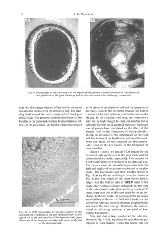
![Properties of buckytubes and derivatives 119
Fig. 11. (a) and (b) are HREM images of the deposited rods produced by the glow discharge and by the
conventional arc discharge, respectively.
polygonal and cone-shaped caps are formed by incor- nanoparticles. An effort to promote the growth of car-
porating pentagons into the hexagonal network. H e bon nanotubes and eliminate the formation of carbon
speculated that the formation of the pentagons may nanoparticles is presently underway.
result from a depletion of carbon in plasma near the
end of cathode[2]. Our experimental results offer ev-
4. CONCLUSIONS
idence for the above speculation. Fluctuations of car-
bon species caused by a discontinuous arc discharge In this article, we have reported the structural,
may be responsible for the formation of short tubes magnetic, and transport properties of bundles of
with the caps, consisting of pentagons and other buckytubes produced by an arc discharge. By adjust-
defects. ing the arc mode into a stable glow discharge, evenly
Based on these experimental results, one can spec- spaced and parallel buckybundles with diameters up to
ulate on the influence of the arc mode on the yield and 200 pm have been synthesized. The magnetic suscep-
distribution of the bundles. For the glow discharge, tibility of a bulk sample of buckybundles is -10.75 x
the plasma is continuous, homogeneous, and stable. emu/g for the magnetic field parallel to the bun-
In other words, the temperature distribution, the elec- dle axes, which is approximately 1.1 times the perpen-
tric field which keeps growing tube tips open[47], and dicular value and 30 times larger than that of c60.
the availability of carbon species (atoms, ions, and The magnetoresistance (MR) and Hall coefficient mea-
radicals) are continuous, homogeneous, and stable surements on the buckybundles show a negative MR
over the entire central region of the cathode. Accord- at low temperature, a positive MR at a temperature
ingly, a high yield and better quality buckytubes above 6 0 K , and a conductivity which increases ap-
should occur over the entire central region of the cath- proximately linearly with temperature. Our results
ode. These are consistent with what we observed in show that a buckybundle may best be described as a
Fig. 9 (a), Fig. 10, and Fig. 11 (a). For the conven- semimetal.
tional arc discharge, we can speculate that the arc
starts at a sharp edge near the point of closest ap- Acknowledgements-We are grateful to A. Patashinski for
proach, and after vaporizing this region it jumps to useful discussions. This work was performed under the sup-
what then becomes the next point of closest approach port of NSF grant #9320520 and DMR-9357513 (NYI award
(usually within about a radius of the arc area), and so for VPD). The use of MRC central facilities supported by
NSF is gratefully acknowledged.
on. The arc wanders around on the surface of the end
of the anode, leading, on the average, t o a discontin-
uous evaporation process and an instability of the elec- REFERENCES
tric field. This kind of violent, randomly jumping arc
discharge is responsible for the low yield and the low 1. S. Iijima, Nature 354, 56 (1993).
2. S. Iijima, T. Ichihashi, and Y. Ando, Nature 356, 776
quality of the deposited buckytubes. This is, again,
( 1992).
consistent with what we showed in Fig. 9 ( b ) and 3. T. W. Ebbesen and P. M. Ajayan, Nature 358, 220
Fig. 11 (b). Note also from Fig. 11 that carbon nano- (1992).
tubes and nanoparticles coexist in both samples. The 4. Y. Ando and S. Iijima, Jpn. J. Appl. Phys. 32, L107
coexistence of these two carbonaceous products may (1993).
5. T. W. Ebbesen, H. Hiura, J. Fujita, Y. Ochiai, S. Mat-
suggest that some formation conditions, such as the sui, and K. Tanigaki, Chem. Phys. Lett. 209, 83 (1993).
temperature and the density of the various carbon spe- 6. Y. Saito, T. Yoshikawa, M. Inagaki, M. Tomita, and T.
cies, are almost the same for the nanotubes and the Nayashi, Chem. Phys. Lett. 204, 277 (1993).](https://image.slidesharecdn.com/13709313-carbon-nanotubes-120928071547-phpapp01/85/13709313-carbon-nanotubes-132-320.jpg)
![ELECTRONIC PROPERTIES OF CARBON NANOTUBES:
EXPERIMENTAL RESULTS
J.-P. ISSI,’ L. LANGER,’ HEREMANS? C. H.
J. and QLK~
‘Unite PCPM, Universitt Catholique de Louvain, Louvain-la-Neuve, Belgium
2General Motors Research and Development Center, Warren, MI 48090, U.S.A.
(Received 6 February 1995, accepted 10 February 1995)
Abstract-Band structure calculations show that carbon nanotubes exist as either metals or semiconduc-
tors, depending on diameter and degree of helicity. When the diameters of the nanotubes become com-
parable to the electron wavelength, the band structure becomes noticeably one-dimensional. Scanning
tunneling microscopy and spectroscopy data on nanotubes with outer diameters from 2 to 10 nm show
evidence of onedimensional behavior: the current-voltage characteristics are consistent with the functional
energy dependence of the density-of-states in 1D systems. The measured energy gap values vary linearly
with the inverse nanotube diameter. Electrical resistivity and magnetoresistance measurements have been
reported for larger bundles, and the temperature dependence of the electrical resistance of z single micro-
bundle was found t o be similar to that of graphite and its magnetoresistance was consistent with the for-
mation of Landau levels. Magnetic susceptibility data taken on bundles of similar tubes reveal a mostly
diamagnetic behavior. The susceptibility at fields above the value at which the magnetic length equals the
tube diameter has a graphite-like dependence on temperature and field. At low fields, where electrons sari.-
ple the effect of the Finite tube diameter, the susceptibility has a much more pronounced temperature
dependence.
Key W70rds--Carbon nanotubes, scanning tunneling microscopy, spectroscopy, magnetoresistance, elec-
trical resistivity, magnetic susceptibility.
1. INTRODUCTION perimental challenges result from the fact that tubes
are often produced in bundles, so that obtaining data
The existence of carbon nanotubes with diameters on single, well-characterized tubes has not yet been
small compared to the de Broglie wavelength has been achieved. We review here some experimental observa-
described by Iijima[l,2,3] and others[4,5]. The energy tions relevant to the electronic structure of individ-
band structures for carbon nanotubes have been cal- ual nanotubes or on bundles of nanotubes: combined
culated by a number of authors and the results are scanning tunneling microscopy and spectroscopy,
summarized in this issue by M.S. Dresselhaus, 6.Dres- temperature-dependent resistivity, magnetoresistance
selhaus, and R. Saito. In short, the tubules can be (MR), and magnetic susceptibility.
either metallic or semiconducting, depending on the
tubule diameter and chirality[6,7,8]. The calculated
2. SCANNING TUNNELING
density of states[8] shows I/(KEj)’’’ singularities
SPECTROSCOPY STUDIES
characteristic of one-dimensional (1D) systems. The
separation between the singularities around the Fermi Scanning tunneling spectroscopy (STS) can, in prin-
energy is the energy gap for the tubes that are semi- ciple, probe the electronic density of states of a single-
conducting, and scales linearly with the inverse of the wall nanotube, or the outermost cylinder of a multi-wall
tube outer diameter[7,8]. This contrasts with the case tubule, or of a bundle of tubules. With this technique,
of a rod-shaped quantum wire, for which the gap is it is further possible to carry out both STS and scan-
expected to scale with the inverse square of the diam- ning tunneling microscopy (STM) measurements at the
eter. The relevant energy scale for the gap in carbon same location on the same tubule and, therefore, to
nanotubes is the nearest-neighbor overlap integral in measure the tubule diameter concurrently with the STS
graphite (3.14 eV)[9]. This makes room-temperature spectrum. No reports have yet been made of a deter-
observation of the quantum size effects, in principle, mination of the chiral angle of a tubule with the STM
possible in nanotubes with diameters in the nm range, technique. Several groups have, thus far, attempted
because the sublevel energy separations are of the or- STS studies of individual tubules.
der of 1 eV. The first report of current-voltage (I-V) measure-
Experimental measurements to test these remark- ments by Zhang and Lieber[lO] suggested a gap in the
able theoretical predictions of the electronic structure density of states below about 200 MeV and semicon-
of carbon nanotubes are difficult to carry out because ducting behavior in the smallest of their nanotubes
of the strong dependence of the predicted properties (6 nm diameter). The study that provides the most de-
on tubule diameter and chirality. Ideally, electronic or tailed test of the theory for the electronic properties
optical measurements should be made on individual of the 1D carbon nanotubes, thus far, is the combined
single-wall nanotubes that have been characterized STM/STS study by Olk and Heremans[111, even though
with regard to diameter and chiral angle. Further ex- it is still preliminary. In this study, more than nine
121](https://image.slidesharecdn.com/13709313-carbon-nanotubes-120928071547-phpapp01/85/13709313-carbon-nanotubes-134-320.jpg)
![122 J.-P. ISSI et ul.
Fig. 1. Topographic STM scan of a bundle of nanotubes. STS data were collected at points (I), (2), and
(3), on tubes with diameters of 8.7, 4.0,and 1.7 nm, respectively. The diameters were determined from
image cross-sections of the variations in height in a direction perpendicular to the tubes (adapted from
Olk et u/.[ll]).
individual multilayer tubules with diameters ranging bules (trace 2 for a tubule with diameter = 4.0 nm, and
from 2 to 10 nm, prepared by the standard carbon-arc trace 3 for a tubule with diameter = 1.7 nm) show pla-
technique, were examined. STM measurements were teaus in the I/V characteristics at zero current. This
taken first, and a topographic STM scan of a bundle rectifying behavior is the signature of semiconducting
of nanotubes is shown in Fig. 1. The exponential re- tubules. The dI/dV plot in the inset crudely mimics a
lation between the tunneling current and the tip-to- 1D density of states, the peaks in the dI/dV plot be-
tubule distance was experimentally verified to confirm
that the tunneling measurements pertain to the tubule
and not to contamination on the tubule surface. From
these relations, barrier heights were measured to estab-
lish the range in which the current-voltage character-
istics can be taken for further STS studies. The image
in Fig. 1 is used to determine the diameter of the in-
dividual tubule on which the STS scans are carried
out. During brief interruptions in the STM scans, the
instrument was rapidly switched to the STS mode of
operation, and I-V plots were made on the same re-
gion of the same tubule as was characterized for its di-
ameter by the STM measurement. The I-V plots for
three typical tubules, identified (1)-(3), are shown in
Fig. 2. The regions (1)-(3) correspond to interruptions
in the STM scans at the locations identified by crosses
in the topographic scan, Fig. 1. Although acquisition
of spectroscopic data in air can be complicated by
contamination-mediated effects on the tunneling gap,
several studies on a wide variety of surfaces have been
Fig. 2. Current-voltage characteristics taken at points (l), (2),
reported[l2]. Trace (1) in Fig. 2 , taken on a tube with and (3) in Fig. 3. The top insert shows the conductance versus
8.7 nm diameter, has an ohmic behavior, providing ev- voltage plot, for the data taken at point (3) (adapted from
idence for the metallic nature of that tubule. Two tu- Olk et ul.[ll]).](https://image.slidesharecdn.com/13709313-carbon-nanotubes-120928071547-phpapp01/85/13709313-carbon-nanotubes-135-320.jpg)
![Electronic properties of carbon nanotubes 123
ing attributed to [I/(&, - E)’”] -type singularities in diameter and a few pm length. Second, this sample
the 1D density of states seen in the density of states with its contacts must be characterized to determine
versus energy diagrams calculated in[8]. Several I-V its exact diameter and helicity. To take up this chal-
curves were collected along the length of each tube. lenge it is necessary to resort to nanotechnologies.
Reproducible spectra were obtained on 9 tubes with Before reviewing the results of different measure-
different diameters. ments, we need to first briefly describe the nature of
The energy gap of the semiconducting tubes was es- the deposit formed during the carbon-arc experiment
timated around V = 0 V by drawing two tangents at the in a way first proposed by EbbesentS]. He suggested
points of maximum slope nearest zero in the I-V spec- that the carbon nanotubes produced by classical car-
tra, and measuring the voltage difference between the bon arc-discharge present a fractal-like organization.
intercepts of these tangents with the abscissa. A plot of The deposit on the negative electrode consists of a
these energy gaps versus inverse tube diameter for all hard gray outer shell and a soft black fibrous core con-
samples studied is shown in Fig. 3[11]. Surface contam- taining the carbon nanotubes. If we examine in detail
ination may account for the scatter in the data points, this core material by scanning electron microscopy, we
though the correlation between Egand the inverse di- observe a fractal-like structure. This means that the
ameter shown in Fig. 3 is illustrated by the dashed line. black core is made of fiber-like entities that are, in re-
The data in Fig. 3 is consistent with the predicted de- ality, bundles of smaller fiber-like systems. These
pendence on the inverse diameter[ 131. The experimen- smaller systems are, in turn, formed of smaller bundles,
tally measured values of the bandgaps are, however, and so on. The micro-bundle, which is the smallest
about a factor of two greater than the theoretically bundle, consists of a few perfectly aligned nanotubes
estimated ones on the basis of a tight binding calcu- of almost equal lengths. Finally, each of these individ-
lation (full line in Fig. 3)[7,13]. Further experimental ual nanotubes is generally formed of several concen-
and theoretical work is needed to reach a detailed un- tric single-shell nanotubes.
derstanding of these phenomena. The fractal-like organization led, therefore, to con-
ductivity measurements at three different scales: (1)
the macroscopic, mm-size core of nanotube contain-
3. ELECTRICAL RESISTIVITY AND
ing material, (2) a large (60 pm) bundle of nanotubes
MAGNETORESISTANCE
and, (3) a single microbundle, 50 nm in diameter.
The remarkable theoretical predictions mentioned These measurements, though they do not allow direct
above are even more difficult to verify by experimen- insights on the electronic properties of an individuai
tal measurements in the case of electrical conductivity. tube give, nevertheless, at a different scale and within
Ideally, one has to solve two experimental problems. certain limits fairly useful information on these
First, one has to realize a four-point measurement on properties.
an individual nanotube. That means four contacts on Ebbesen[4] was the first to estimate a conductiv-
a sample with typical dimensions of the order of a nm ity of the order of Qm for the black core bulk
material existing in two thirds of tubes and one third
of nanoparticles. From this observation, it may nat-
urally be inferred that the carbon arc deposit must
1.6 contain material that is electricaliy conducting. An
analysis of the temperature dependence of the zero-
field resistivity of similar bulk materials[ 14,151 indi-
cated that the absolute values of the conductivity were
1.2 very sample dependent.
Song et al. [16] reported results relative to a four-
n point resistivity measurement on a large bundle of car-
3
-0.8
bon nanotubes (60 pm diameter and 350 pm in length
between the two potential contacts). They explained
their resistivity, magnetoresistance, and Hall effect re-
sults in terms of a conductor that could be modeled
as a semimetal. Figures 4 (a) and (b) show the mag-
netic field dependence they observed on the high- and
low-temperature MR, respectively.
At high temperature, the conductivity was found
to increase linearly with temperature and the observed
high-temperature MR was positive. In fact, by fitting
the data using a simple two-band model[l7] the au-
thors obtained the theoretical curve in Fig. 4 (a). The
Fig. 3. Energy gap versus inverse nanotube diameter, for the fitting parameters showed that the ratio u,/a,, where
nine nanotubes studied; the dashed line is a regression
through the points, the full line is a calculation for semicon- up and a are the partial conductivities of holes and
,
ducting zigzag nanotubes[7,13] (adapted from Olk et aL[ll]). electrons, respectively, decreases with increasing tem-](https://image.slidesharecdn.com/13709313-carbon-nanotubes-120928071547-phpapp01/85/13709313-carbon-nanotubes-136-320.jpg)
![124 J.-P. ISSI et al.
nanotube structures like microbundles, or even better,
single nanotubes. A rather sophisticated technique,
namely submicronic lithographic patterning of gold
films with a scanning tunneling microscope[ 181, was
developed by Langer et al. [ 191 to attach two electri-
cal contacts to a single microbundle. This direct elec-
trical resistance measurement on this quasi-1D system
excludes the errors that may result from the situations
described in (2) and (4) in the last paragraph. The re-
ported temperature dependence measured from 300 K
down to 0.3 K by Langer et al. [19] is shown in Fig. 5.
Above 2 K, some interesting information was obtained
by fitting the experimental zero-field resistance data
to a simple two-band (STB) model successfullyapplied
by Klein[20-22] to semimetallic graphite. In this STB-
model, the electron and hole densities, n andp, respec-
tively, can be expressed by:
p = C,k,Tln[l + exp[(A - EF)/kBTII (2)
Fig. 4. (a) Magnetic field dependence of the high- and low-
temperature MR, respectively. The solid lines are calculated
using a simple two-band model for (a) and the 2D weak 500 I , , , , . 1 1
localization theory for (b) (after Song et a/.[16]). I
perature implying that, as the temperature increases
the Fermi level shifts closer to the conduction band.
, +
The increase in total conductivity, a up,with tem-
400
perature was attributed to an increase in electron con-
centration. Song et al. [16] attributed the fact that
above 60 K the conductivity increases almost linearly 1
with temperature, as opposed to an exponential or
variable range hopping-type temperature dependence, - I11 I1
to a semimetallic behavior.
At low temperature and low field, the observed MR
8
Y
was found to be negative, Fig. 4 (b), while positive MR
contributions were increasingly important for higher 2
fields. While 1D weak localization (WL) was found by
Song et al. [lq to be inadequate to describe the data,
they claimed that 2D WL fit the experimental results
for the temperature dependence of the resistivity and
the MR at low temperature and low fields. They esti- '
8
mated a resistivity of 0.65 x lop4 Qm at 300 K and 0%
1.6 x Om at 5 K. However, the actual resistivity I
w
of the metallic tubules along their axis should be much
lower than these values for many reasons: (1) as pre-
dicted by the theory described in [7], only one third
of the tubules are conducting; (2) the filling factor of
a large bundle like the measured one is less than 1; (3)
when the tubes are not single-walled, the cross-section
of the nanotubes where conduction occurs is unknown
and affected by their inner structure and, finally, (4)
the nanotube is anisotropic.
To avoid the problems described above relative to
the interpretation of the results, it is necessary to work
at a lower scale. In other words, modern nanotech-
nology must be used to contact electrically smaller](https://image.slidesharecdn.com/13709313-carbon-nanotubes-120928071547-phpapp01/85/13709313-carbon-nanotubes-137-320.jpg)
![Electronic properties of carbon nanotubes 125
where Ef is the Fermi energy and A is the band over- these results are not consistent with WL. In the frame-
lap. C, and C, are the fitting parameters. The results work of WL, the observed temperature independent
of this fit, which is shown in Fig. 5, is obtained for MR below 10 K and down to 1 K could only be ex-
A = 3.7 MeV and with the Fermi energy right in the plained in the presence of large amounts of magnetic
middle of the overlap. Ideally, an overlap of the or- impurities, as is the case for some pyrocarbons[25].
der of 40 MeV is expected for the case of multilayered However, in the present case, the spectrographic anal-
nanotubes[23] with an interlayer configuration simi- ysis performed by Heremans et al. [26] excludes the
lar to that of crystalline graphite. For real nanotubes presence of magnetic impurities.
instead, a turbostratic stacking of the adjacent layers Below 2 K, an unexpected temperature dependence
would reduce drastically the interlayer interactions, as of the resistance and MR is observed. As shown in
in disordered graphite, and so it is not surprising to Fig. 5, the resistance presents, after an initial increase,
find a band overlap 10 times smaller than in crystalline a saturation or a broad maximum and an unexplained
graphite. This implies also that, within the frame of sharp drop when a magnetic field is applied (see Fig. 6).
the STB model, the carrier density is 10 times smaller. Further theoretical work is needed to get a better un-
The apparent electrical resistivity (4 x Om) mea- derstanding of these striking physical observations. Fi-
sured at low temperature is certainly still higher than nally, it is interesting to note that Whitesides and
the resistivity of a single nanotube. In fact, the con- Weisbecker[27] developed a technique to estimate the
ductance of the system is dominated by that of the conductivity of single nanotubes by dispersing nano-
nanotubes with the highest conductance (Le., the semi- tubes onto lithographicallydefined gold contacts to re-
metallic nanotubes). All these nanotubes are not nec- alize a 'nano-wire' circuit. From this 2-point resistance
essarily in contact with the measuring probes. Finally, measurement and, after measuring the diameter of the
the inner structure of each individual nanotube in this single nanotubes by non-contact AFM, they estimated
microbundle remains unknown. the room-temperature electrical resistivity along the
By applying a magnetic field normal to the tube nanotube axis to be 9.5 x low5 Qm. This is consistent
axis, Langer et a . I191 observed a MR (Fig. 6) which,
i with the values obtained for a microbundle by Langer
in contrast to the case of graphite, remains negative et a/. 1191.
at all fields. The negative MR was found consistent The most promising way to study the electrical con-
with the formation of Landau levels. Ajiki and Ando[24] ductivity of a single nanotube is, thus, tightly depen-
have predicted that a magnetic field applied perpen- dent on the development or/and the adaptation of
dicularly to the sample axis should introduce a Lan- modern nanolithographic techniques. The goal to
dau level at the crossing of the valence and conduction achieve is within reach and a detailed study of the elec-
bands. It results in an increase of the density of states tronic properties with reference to helicity and diam-
at the Fermi level and, hence, a reduction of the re- eter will provide instrumental information about these
sistance, which is in agreement with the experimental fascinating materials.
data. Moreover, the theory predicts a MR that is tem-
perature independent at low temperature and decreas- 4. MAGNETIC SUSCEPTIBILITY
ing when kBTbecomes larger than the Landau level.
This is also what was experimentally observed. Thus, The presence of aromatic-like electrons strongly de-
in contrast to what was reported by Song et a/.[16], termines the magnetic susceptibility of the diverse
forms of carbons. The susceptibility of diamond
(-4.9 x emu/g) is ascribed to diamagnetic con-
tributions from core and valence electrons, and a Van
Vleck paramagnetic term[28]. Graphite has an aniso-
tropic diamagnetic susceptibility[29]. The susceptibil-
ity of graphite[29,30] parallel to the planes is about
equal to the free atom susceptibility of -5 x
emu/g, but when the magnetic field is aligned paral-
lel to the c-axis, the susceptibility of graphite (-30 X
lop6 emu/g below loOK) is due mainly to free elec-
tron contributions and is much larger. The magnetic
susceptibility of C60 (-3.5 x emulg) and C70
(-5.9 x 1 0 - ~emu/g) is small again[31,32], as a result
of a cancellation between a diamagnetic and a para-
-0.35 '
0
' ' '
4
I
8 12 16
magnetic term.
In the light of these results, it is not surprising that
a very large anisotropy has been calculated[24] to ex-
MAGNETIC FIELD [TI ist in the magnetic susceptibility of nanotubes. The
susceptibility with the field parallel to the tube axis is
Fig. 6. The magnetic field dependence of the magnetoresis-
tance at different temperature for the same microbundle mea- predicted to be as much as 3 orders of magnitude
sured in Fig. 5 (after Langer et n1.[19]). smaller than that with the field perpendicular. Again,](https://image.slidesharecdn.com/13709313-carbon-nanotubes-120928071547-phpapp01/85/13709313-carbon-nanotubes-138-320.jpg)
![126 J.-P. ISSI et al.
measurements on individual single-wall well-charac-
-
terized tubes have not been published to date. Exper- 0.0
iments usually involve gathering nanotube material
from several growths, to obtain quantities of material (r
-0.2
on the order of tens of mg. A measurement on ori- 2
ented bundles of tubes[30] at 0.5 T as a function of E
a,
temperature gives evidence for anisotropy. Such a "-0.4
measurement is, however, easily affected by a small CI
c
misalignment of the sample. It is, therefore, possible a
that the data reported for the case where the field is
E -0.6
0
parallel to the tube axis are, in fact, dominated by con- r
tributions from the perpendicular susceptibility. -0.8
A second study [33] on samples that contain a mix-
ture of nanotubes, together with several percent
-1 .o
"buckyonion"-type structures, was carried out at tem- 0 20000 40000 60000
peratures between 4.5 and 300 K, and fields between Magnetic Field (Oe)
0 and 5.5 T. The moment M i s plotted as a function
of field in Fig. 7, for the low-field range, and in Fig. 8 at the temperatures shown atthe moment of carbon nanotubes
Fig. 8. Field dependence of
high magnetic fields (after Here-
for the high-field range. The field dependence is mans et al. [26]).
clearly non-linear, unlike that of graphite, in which
both the basal plane and the c-axis moments are lin-
ear in field, except for the pronounced de Haas-van the tube diameter. The sample, however, consists of a
Alphen oscillations at low temperature. mixture of semiconducting and metallic tubes. The
The a.c. susceptibility (x = dM/dH, where M i s the
component of x perpendicular to the tube axis domi-
moment), measured at 5,0.4, and 0.04 T, is shown as
nates the measured susceptibility, and the value is ex-
a function of temperature in Fig. 9. Three regimes of
pected to scale with 1/EF[24]. The electrical resistivity
magnetic fields are identified in ref. [33]. The high-
data show that, even in the metallic samples, the en-
field susceptibility (at 5 T) has a temperature depen- ergy gap is on the order of a few MeV[19]. At room
dence similar to that of graphite, but a magnitude temperature kBT> EF for both metallic and semicon-
reduced by a factor of 2. In this regime, the magnetic
ducting samples. Thus, a thermally activated behavior
radius (hb/eB)"' becomes shorter than the tube diam-
is expected for the average susceptibility. Furthermore,
eter. The electronic diamagnetism is then a local probe
carriers may be scattered at a temperature-dependent
of the graphene planes, and its value is expected to be
rate, for instance by acoustic phonons. These two
the geometrical average of that of rolled-up graphene.
mechanisms are consistent with the much more pro-
Because with the field in the basal plane, x is much
nounced temperature dependence of the low-field
smaller than along the c-axis, this geometrical average
susceptibility of nanotubes than of graphite. More
comes out to be about +[30].The low-field susceptibil-
quantitative models remain to be developed. In the in-
ity (at 0.04 T) is a better probe of the finite size effects
of the tubes, because the magnetic length is larger than
L' ' " ' " ' "' " ' " ' " I ' " ' " '"# " ' " ' " '4
0.00
m
cn
>
E -0.04
a,
W
4
S
?
4 -0.08
45
.
-0.12
0 1000 2000 3000 4000 5000 6000
Magnetic Field (Oe)
Fig. 7. Field dependence of the moment of carbon nanotubes Fig. 9. Susceptibility of carbon nanotubes versus tempera-
at the temperatures shown at low magnetic fields (after Here- ture at the different fields identified in the figure (after Here-
mans et al.[26]). mans el a/.[26]).](https://image.slidesharecdn.com/13709313-carbon-nanotubes-120928071547-phpapp01/85/13709313-carbon-nanotubes-139-320.jpg)
![Electronic properties of carbon nanotubes 127
termediate field regime (around 0.5 T), x is probably model developed by Ajiki and Ando[%]. From the tem-
sensitive to the fact that the sample consists of a mix- perature dependence of the electrical resistance of this
ture of semiconducting and metallic tubes. Further- microbundle, it appears that the measured nanotubes
more, the tubes in that mixture have different diameters are semimetallic and behave like rolled-up graphene
and, thus, go from the low-field to the high-field re- sheets. Below 1 K, the results are puzzling and yet un-
gime at different fields. Figure 10 shows a summary explained. Susceptibility was measured on 20-mg sam-
of the a.c. susceptibilitiesof various forms of carbon, ples containing a large variety of tubes. Free carrier
as an easy ready reference. The values for diamond contributes to the diamagnetic behavior of nanotubes,
and the basal plane of graphite represent the atomic which is similar to that of graphite when the magnetic
contributions, and the c-axis of graphite and the sus- length is smaller than the tube diameter. The low-field
ceptibilities of nanotubes are dominated by free car- diamagnetism contains more information about the
rier contributions. specific band structure of the tubes.
5. CONCLUSIONS Acknowledgements-The authors gratefully acknowledge
much help from M.S. Dresselhaus and G . Dresselhaus in the
The purpose of this work is to review experimen- preparation of this article.
tal data on the electronic properties of carbon nano-
tubes. Although most of the theoretical work has been
focused on single-walled individual tubes, performing REFERENCES
transport and other measurements on such entities is
extremely difficult and remains unachieved. Combined 1. S. Iijima, Nature (London) 354, 56 (1991).
2. S. Iijima, Mater. Sci. Eng. B19, 172 (1993).
STM and STS measurements access single tubes within 3. S. Iijima, T. Ichihashi, and Y. Ando, Nature (London)
bundles containing a few a tubes. They provide exper- 356, 776 (1992).
imental evidence that graphite nanotubes behave as 4. T. W. Ebbesen and P. M. Ajayan, Nature (London) 358,
nanowires, with a density of states and an energy gap 220 (1992).
5. T. W. Ebbesen, H. Hiura, J. Fujita, Y. Ochiai, S. Mat-
dependence on inverse diameter as predicted. Studies sui, and K. Tanigaki, Chem. Phys. Lett. 209, 83 (1993).
in ultra-high vacuum are needed to provide more quan- 6. J. C. Charlier and J. P. Michenaud, Phys. Rev. Lett. 70,
titative data on the dependence of the gap on diameter. 1858 (1993). J. C. Charlier, Carbon Nunotubes and Ful-
No electrical resistance measurements are currently lerenes. PhD thesis, Catholic University of Louvain, May
1994.
available on a well-characterized single nanotube. 7. C. T. White, D. H. Roberston, and J. W. Mintmire,
However, electrical resistivity measurements performed Phys. Rev. B 47, 5485 (1993).
at low temperature on a large nanotube bundle were 8. R. Saito, G. Dresselhaus, and M. S. Dresselhaus, J.
interpreted in terms of a 2D WL. On the other hand, Appl. Phys. 73, 494 (1993). M. S. Dresselhaus, G. Dres-
MR data obtained for a single microbundle were con- selhaus, and R. Saito, Solid State Commun. 84, 201
(1992).
sistent with the formation of Landau levels using the 9. R. Saito, M. Fujita, G. Dresselhaus, and M. S. Dressel-
haus, In Electrical, Optical and Magnetic Properties of
Organic Solid State Materials, MRS Symposia Proceed-
ings, Boston (Edited by L. Y. Chiang, A. E Garito, and
D. J. Sandman), vol. 247, page 333. Materials Research
Society Press, Pittsburgh, PA (1992).
10. 2. Zhang and C. M. Lieber, Appl. Phys. Lett. 62,2792
(1993).
11. C. H. Olk and J. P. Heremans, J. Mater. Res. 9, 259
(1994).
12. N. Venkateswaran, K. Sattler, U. Muller, B. Kaiser, 6.
J
Raina, and J. Xhie, J. Vac. Sci. Technol.B9, 1052 (1991).
M. Jobin, R. Emch, F. Zenhausern, S. Steinemann, and
P. Descouts, J. Vac. Sci. Technol. B9, 1263 (1991). 2.
Zhang, C. M. Lieber, D. S. Ginley, R. J. Baughman, and
B. Morosin, J. Vac. Sci. Technol. B9, 1009 (1991). H.
4- -
Enomoto, H. Ozaki, M. Suzuki, T. Pujii, and M.
I Grappite, H in-plane Yamaguchi, J. Vac. Sci. Technol. B9, 1022 (1991).
7-
) 0-0 -0-
13. M. S. Dresselhaus, R. A. Jishi, G. Dresselhaus, and Ri-
k*+++ ichiro Saito, Fullerenes (1994). St. Petersburg, Russia
Diamond’ - Fullerene workshop, October 1993.
I I I I **,,,
<-C60 , 14. R. Heyd, A. Charlier, J. F. Marechi, E. McRae, and
10 100 1000 0. V. Zharikov, Solid State Commun. 89, 989 (1994).
Temperature (K) 15. R. Seshardi, H. N. Aiyer, A. Govindaraj, and C. N.
Rao, Solid State Commun. 91, 195 (1994).
Fig. 10. Temperature dependence of the magnetic suscepti- 16. S. N. Song, X. K. Wang, R. P. H. Chang, and J. B. Ket-
bility of various carbon-based materials. The data on HOPG terson, Phys. Rev. Lett. 12, 697 (1994).
(H//c) are taken at 200 Oe. The data reported for nanotubes, 17. K. Noto and T. Tsuzuku, Jpn. J. Appl. Phys. 14, 46
graphite (H in-plane), and diamond, were taken at 4 kOe, (1975).
those on diamond at 8 kOe. The ordinate axis is negative (af- 18. L. Stockman, G. Neuttiens, C. Van Haesendonck, and
ter Heremans et ai. [26]). Y. Bruynseraede, Appl. phys. Lett. 62, 2935 (1993).](https://image.slidesharecdn.com/13709313-carbon-nanotubes-120928071547-phpapp01/85/13709313-carbon-nanotubes-140-320.jpg)

![VIBRATIONAL MODES OF CARBON NANOTUBES;
SPECTROSCOPY AND THEORY
and
P. C . EKLUND,’ M. HOLDEN,’ R. A. JISHI*
J.
’Department of Physics and Astronomy and Center for Applied Energy Research,
University of Kentucky, Lexington, KY 40506, U.S.A.
’Department of Physics, Massachusetts Institute of Technology, Cambridge, MA 02139, U.S.A.;
Department of Physics, California State University, Los Angeles, CA 90032, U S A .
(Received 9 February 1995; accepted in revised form 21 February 1995)
Abstract-Experimental and theoretical studies of the vibrational modes of carbon nanotubes are reviewed.
The closing of a 2D graphene sheet into a tubule is found to lead to several new infrared (1R)- and Raman-
active modes. The number of these modes is found to depend on the tubule symmetry and not on the di-
ameter. Their diameter-dependent frequencies are calculated using a zone-folding model. Results of Raman
scattering studies on arc-derived carbons containing nested or single-wall nanotubes are discussed. They
are compared to theory and to that observed for other sp2 carbons also present in the sample.
Key Words-Vibrations, infrared, Raman, disordered carbons, carbon nanotubes, normal modes.
1. INTRODUCTION 2. OVERVIEW OF RAMAN SCATTERING
FROM SP2 CARBONS
In this paper, we review progress in the experimental
detection and theoretical modeling of the normal modes Because a single carbon nanotube may be thought
of vibration of carbon nanotubes. Insofar as the theo- of as a graphene sheet rolled up to form a tube, car-
retical calculations are concerned, a carbon nanotube bon nanotubes should be expected to have many prop-
is assumed to be an infinitely long cylinder with a mono- erties derived from the energy bands and lattice
layer of hexagonally ordered carbon atoms in the tube dynamics of graphite. For the very smallest tubule di-
wall. A carbon nanotube is, therefore, a one-dimensional ameters, however, one might anticipate new effects
system in which the cyclic boundary condition around stemming from the curvature of the tube wall and the
the tube wall, as well as the periodic structure along closing of the graphene sheet into a cylinder. A natu-
the tube axis, determine the degeneracies and symmetry ral starting point for the discussion of the vibrational
classes of the one-dimensional vibrational branches modes of carbon nanotubes is, therefore, an overview
i1-31 and the eIectronic energy bands[4-12]. of the vibrational properties of sp2 carbons, includ-
Nanotube samples synthesized in the laboratory are ing carbon nanoparticles, disordered sp2 carbon, and
typically not this perfect, which has led to some confu- graphite. This is also important because these forms
sion in the interpretation of the experimental vibrational of carbon are also often present in tubule samples as
spectra. Unfortunately, other carbonaceous material “impurity phases.”
(e.g., graphitic carbons, carbon nanoparticles, and In Fig. la, the phonon dispersion relations for 3D
amorphous carbon coatings on the tubules) are also graphite calculated from a Born-von Karman lattice-
generally present in the samples, and this material dynamical model are plotted along the high symmetry
may contribute artifacts to the vibrational spectrum. directions of the Brillouin zone (BZ). For comparison,
Defects in ithe wall (e.g., the inclusion of pentagons we show, in Fig. lb, the results of a similar calcula-
and heptagons) should also lead to disorder-induced tion[29] for a 2D infinite graphene sheet. Interactions
features in the spectra. Samples containing concentric, up to fourth nearest neighbors were considered, and
coaxial, “nested” nanotubes with inner diameters the force constants were adjusted to fit relevant exper-
-8 nm and outer diameters -80 nm have been syn- imental data in both of these calculations. Note that
thesized using carbon arc methods[l3,14], combustion there is little dispersion in the k, (I? to A ) direction
fllames[l5], and using small Ni or Co catalytic parti- due to the weak interplanar interaction in 3D graphite
cles in hydrocarbon vapors[lb-201. Single-wall nano- (Fig. IC). To the right of each dispersion plot is the
tubes (diameter 1-2 nm) have been synthesized by calculated one-phonon density of states. On the energy
adding metal catalysts to the carbon electrodes in a dc scale of these plots, very little difference is detected
arc[21,22] To date, several Raman scattering stud-
~
between the structure of the 2D and 3D one-phonon
ies[23-281 of nested and single-wall carbon nanotube density of states. This is due to the weak interplanar
samples have appeared. coupling in graphite. The eigenvectors for the optically
129](https://image.slidesharecdn.com/13709313-carbon-nanotubes-120928071547-phpapp01/85/13709313-carbon-nanotubes-142-320.jpg)
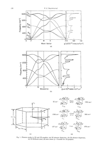
![Vibrational modes of carbon nanotubes 131
allowed r-point vibrations for graphite (3D) are shown
in Fig. Id, which consist of two, doubly degenerate,
Raman-active modes (E;;) at 42 cm-', E;:' at 1582
cm-I), a doubly degenerate, infrared-active El, mode
at 1588 cm-' , a nondegenerate, infrared-active A Z u
mode at 868 cm-', and two doubly degenerate Bzg
modes (127 cm-', 870 cm-') that are neither Raman-
nor infrared-active. The lower frequency Bii) mode
has been observed by neutron scattering, and the other
is predicted at 870 cm-'. Note the I'-point E l , and
15;;) modes have the same intralayer motion, but dif-
fer in the relative phase of their C-atom displacements
in adjacent layers. Thus, it is seen that the interlayer
interaction in graphite induces only an -6 cm-' split-
(2)
ting between these modes ( w ( E l , ) - @ ( E z ,) = 6
cm-')). Furthermore, the frequency of the rigid-layer,
=
shear mode (o(E2;)) 42 cm-') provides a second
spectroscopic measure of the interlayer interaction be-
cause, in the limit of zero interlayer coupling, we must
have w (E;:) ) + 0.
The Raman spectrum (300 cm-' I I w 3300 cm-')
for highly oriented pyrolytic graphite (HOPG)' is
shown in Fig. 2a, together with spectra (Fig. 2b-e) for
several other forms of sp2 bonded carbons with vary-
ing degrees of intralayer and interlayer disorder. For
HOPG, a sharp first-order line at 1582 cm-' is ob-
served, corresponding to the Raman-active E;:) mode
observed in single crystal graphite at the same fre-
quency[3 I]. The first- and second-order mode fre-
quencies of graphite, disordered sp2 carbons and
carbon nanotubes, are collected in Table 1.
Graphite exhibits strong second-order Raman-
active features. These features are expected and ob- Fig. 2. Raman spectra (T = 300 K) from various sp2 car-
served in carbon tubules, as well. Momentum and bons using Ar-ion laser excitation: (a) highly ordered pyro-
energy conservation, and the phonon density of states lytic graphite (HOPG), (b) boron-doped pyrolytic graphite
determine, to a large extent, the second-order spectra. (BHOPG), (c) carbon nanoparticles (dia. 20 nm) derived
+
By conservation of energy: Aw = Awl hw,, where o from the pyrolysis of benzene and graphitized at 282OoC,
(d) as-synthesized carbon nanoparticles (-85OoC), (e) glassy
and wi ( i = 1,2) are, respectively, the frequencies of carbon (after ref. [24]).
the incoming photon and those of the simultaneously
excited normal modes. There is also a crystal momen-
tum selection rule: hk = Aq, + Aq,, where k and qi
( i = 1.2) are, respectively, the wavevectors of the in- the c-axis (i.e., along the k, direction) is small. Also,
coming photon and the two simultaneously excited there is little in-plane dispersion of the optic branches
normal modes. Because k << qe, where q B is a typical and acoustic branches near the zone corners and edges
wavevector on the boundary of the BZ, it follows that ( M to K ) . This low dispersion enhances the peaks
q l = -q2. For a second-order process, the strength of in the one-phonon density of states, g, ( w )(Fig. la).
the IR lattice absorption or Raman scattering is pro- Therefore, relatively sharp second-order features are
portional to IM(w)12g2(o), where g 2 ( w ) = gl(wl). observed in the Raman spectrum of graphite, which
g,(a,)is the two-phonon density of states subject to correspond to characteristic combination (wl + w2)
the condition that q1 = -q2, and where g,( w ) is the and overtone (2w) frequencies associated with these
one-phonon density of states and IM(w)I2is the ef- low-dispersion (high one-phonon density of states) re-
fective two-phonon Raman matrix element. In cova- gions in the BZ. For example, a second-order Raman
lently bonded solids, the second-order spectra1 features feature is detected at 3248 cm-', which is close to
are generally broad, consistent with the strong disper- 2(1582 cm-') = 3164 cm-', but significantly upshifted
sion (or wide bandwidth) of both the optical and due to the 3D dispersion of the uppermost phonon
acoustic phonon branches. branch in graphite. The most prominent feature in
However, in graphite, consistent with the weak in- the graphite second-order spectrum is a peak close to
terlayer interaction, the phonon dispersion parallel to 2(1360 cm-') = 2720 cm-' with a shoulder at 2698
cm-' ,where the lineshape reflects the density of two-
'HOPG is a synthetic polycrystalline form of graphite phonon states in 3D graphite. Similarly, for a 2D
produced by Union Carbide[30]. The c-axes of each grain graphene sheet, in-plane dispersion (Fig. Ib) of the
(dia; -1 pm) are aligned to -1". optic branches at the zone center and in the acoustic](https://image.slidesharecdn.com/13709313-carbon-nanotubes-120928071547-phpapp01/85/13709313-carbon-nanotubes-144-320.jpg)
![132 P . C. EKLUND ul.
et
Table 1. Table of frequencies for graphitic carbons and nanotubes
Single-wall tubules Nested tubules
Mode Planar graphite Holden$ Holden Chandrabhas Bacsa Kastner
assignment* t et ul. [27] et ul. [28] Hiura et ul.[24] et al. [26] et ul. [25]
(tube dia.) HOPG[31] BHOPG[31] (1-2 nm) (1-2 nm) et ul.[23] (15-50 nm) (8-30 nm) (20-80 nm)
-
42' 49, 58'
127h
86Sg -9mc -700' 86V
870' -900'
1582' 1585' 1 566c'd 1568' 1574' 1583' 158Ia 1582e
1577= 1591e 1592C,d 1594'
158Sg 1575g
1350' 1367' 1341' 1340a 1353' 1356a variesf
1365e 1380'
1620' 1620a
2441' 2450' 2450' 24Sa 2455' 2450' 2455e
2440e
2722' 2122c 2681C*d 2680' 2687' 2709' 2734'
2746e 2153e
2950' 2925' 2925e
2974e
3247' 3240' 31 3180' 3250a 3250a 3252=
3246e 3242e
*Activity: R = Raman-active, ir = infrared-active, S = optically silent, observed in neutron scattering.
?Carbon atom displacement II or I to e.
$Peaks in "difference spectrum" (see section 4.3).
a-eExcitationwavelength: a742 nm, b532 nm, '514 nm, d488 nm, "458 nm; resonance Raman scattering study; 5 r -
absorption study; hfrom neutron scattering; 'predicted.
branches near the zone comers and edges is weak, giv- pend weakly on the laser excitation wavelength[32].
ing rise to peaks in the one-phonon density of states. This unusual effect arises from a resonant coupling of
One anticipates, therefore, that similar second-order the excitation laser with electronic states associated
features will also be observed in carbon nanotubes. with the disordered graphitic material. Small basal
This is because the zone folding (c.f., section 4) pre- plane crystallite size (L,) has also been shown[33] to
serves in the tubule the essential character of the in- activate disorder-induced scattering in the D-band.
plane dispersion of a graphene sheet for q parallel The high frequency E$:)(q = 0) mode has also been
to the tube axis. However, in small-diameter carbon investigated in a wide variety of graphitic materials
nanotubes, the cyclic boundary conditions around the that have various degrees of in-plane and stacking dis-
tube wall activate many new first-order Raman- and order[32], The frequency, strength, and line-width of
IR-active modes, as discussed below. this mode is also found to be a function of the degree
Figure 2b shows the Raman spectrum of Boron- of the disorder, but the peak position depends much
doped, highly oriented pyrolytic-graphite (BHOPG) less strongly on the excitation frequency.
according to Wang et. aZ[32]. Although the BHOPG The Raman spectrum of a strongly disordered sp2
spectrum is similar to that of HOPG, the effect of the carbon material, "glassy" carbon, is shown in Fig. 2e.
0.5"/0 substitutional boron doping is to create in-plane The Eii'-derived band is observed at 1600 cm-' and
disorder, without disrupting the overall AB stacking is broadened along with the D-band at 1359 cm-'.
of the layers or the honeycomb arrangement of the re- The similarityof the spectrum of glassy carbon (Fig. 2e)
maining C-atoms in the graphitic planes. However, the to the one-phonon density of states of graphite (Fig. la)
boron doping relaxes the q = 0 optical selection rule is apparent, indicating that despite the disorder, there
for single-phonon scattering, enhancing the Raman ac- is still a significant degree of sp2 short-range order in
tivity of the graphitic one- and two-phonon density the glassy carbon. The strongest second-order feature
of states. Values for the peak frequencies of the first- is located at 2973 cm-', near a combination band
and second-order bands in BHOPG are tabulated in (wl + w 2 ) expected in graphite at D (1359 m-I) +
Table 1. Significant disorder-induced Raman activity E' (1620 cm-') = 2979 cm-', where the Eig (1620
2g-
in the graphitic one-phonon density of states is ob- cm I ) frequency is associated with a mid-zone max-
served near 1367 cm-', similar to that observed in imum of the uppermost optical branch in graphite
other disordered sp2 bonded carbons, where features (Fig. la).
in the range -1360-1365 cm-' are detected. This The carbon black studied here was prepared by a
band is referred to in the literature as the "D-band," C 0 2 laser-driven pyrolysis of a mixture of benzene,
and the position of this band has been shown to de- ethylene, and iron carbonyI[34]. As synthesized, TEM](https://image.slidesharecdn.com/13709313-carbon-nanotubes-120928071547-phpapp01/85/13709313-carbon-nanotubes-145-320.jpg)
![Vibrational modes of carbon nanotubes 133
images show that this carbon nanosoot consists of dis- tube specified by ( n ,m ) is obtained. If n = m, the re-
ordered sp2 carbon particles with an average particle sulting nanotube is referred to as an “armchair”
diameter of -200 A. The Raman spectrum (Fig. 2d) tubule, while if n = 0 or m = 0, it is referred to as a
of the “as synthesized” carbon black is very similar to “zigzag” tubule; otherwise ( n # m # 0)it is known as
that of glassy carbon (Fig. 2e) and has broad disorder- a “chiral” tubule. There is no loss of generality if it is
induced peaks in the first-order Raman spectrum at assumed that n > m.
1359 and 1600 cm-’, and a broad second-order fea- The electronic properties of single-walled carbon
ture near 2950 cm-’. Additional weak features are nanotubes have been studied theoretically using dif-
observed in the second-order spectrum at 2711 and ferent methods[4-121. It is found that if n - m is a
3200 cm-’ , similar to values in HOPG, but appear- multiple of 3, the nanotube will be metallic; otherwise,
ing closer to 2(1359 CI’I-) = 2718 cm-’ and 2(1600 it w l exhibit a semiconducting behavior. Calculations
il
cm-I) = 3200 cm-’ , indicative of somewhat weaker on a 2D array of identical armchair nanotubes with
3D phonon dispersion, perhaps due to weaker cou- parallel tube axes within the local density approxi-
pling between planes in the nanoparticles than found mation framework indicate that a crystal with a hex-
in HQPG. TEM images[34] show that the heat treat- agonal packing of the tubes is most stable, and that
ment of the laser pyrolysis-derived carbon nanosoot intertubule interactions render the system semicon-
to a temperature THT= 2820°C graphitizes the nano- ducting with a zero energy gap[35].
particles (Le., carbon layers spaced by -3.5 A are
aligned parallel to facets on hollow polygonal parti- 3.1 Symmetry groups of nanotubes
cles). As indicated in Fig. 2c, the Raman spectrum of
A cylindrical carbon nanotube, specified by ( n , m ) ,
this heat-treated carbon black is much more “gra- can be considered a one-dimensional crystal with a
phitic” (similar to Fig. 2a) and, therefore, a decrease
fundamental lattice vector T, along the direction of the
in the integrated intensity of the disorder-induced band tube axis, of length given by[1,3]
at 1360 cm-’ and a narrowing of the 1580 cm-’ band
is observed. Note that heat treatment allows a shoul-
der associated with a maximum in the mid-BZ density
of states to be resolved at 1620 cm-I, and dramati-
cally enhances and sharpens the second-order features. where
dR= d if n - rn # 3dr
3. THEORY OF VIBRATIONS IN
CARBON NANOTUBFS = 3d if n - m = 3dr (3)
A single-,wall carbon nanotube can be visualized by
where Cis the length of the vector in eqn (l), d is the
referring to Fig. 3, which shows a 2D graphene sheet
greatest common divisor of n and m, and r is any in-
with lattice vectors a1 and a2, and a vector C given by
teger. The number of atoms per unit cell is 2 N such
that
where n and m are integers. By rolling the sheet such
N = 2(n2 + m2 + nm)/dR. (4)
that the tip and tail of C coincide, a cylindrical nano-
For a chiral nanotube specified by ( n ,m ) , the cylin-
der is divided into d identical sections; consequently
a rotation about the tube axis by the angle 2u/d con-
stitutes a symmetry operation. Another symmetry op-
eration, R = ($, 7) consists of a rotation by an angle
$ given by
s2
$=27r-
Nd
followed by a translation 7, along the direction of the
tube axis, given by
d
s=T-.
N
The quantity s2 that appears in eqn (5) is expressed in
terms of n and m by the relation
Fig. 3. Translation vectors used to define the symmetry of
a carbon nanotube (see text). The vectors a, and a2 define
the 2D primitive cell. s2 = ( p ( m + 2n) + q ( n + 2m)I ( d / d R ) (7)](https://image.slidesharecdn.com/13709313-carbon-nanotubes-120928071547-phpapp01/85/13709313-carbon-nanotubes-146-320.jpg)
![134 P. C . EKLUND ai.
et
where p and q are integers that are uniquely deter- zag nanotubes, however, have other symmetry oper-
mined by the eqn ations, such as inversion and reflection in planes
parallel to the tube axis. Thus, the symmetry group,
rnp - nq = d, (8) assuming an infinitely long nanotube with no caps, is
given by
subject to the conditions q < m/d and p < n/d.
For the case d = 1, the symmetry group of a chi-
ral nanotube specified by (n, )is a cyclic group of
m
order N given by
Thus e = 6)2,h in these cases. The choice of a,,,or
Dnhin eqn (16) is made to insure that inversion is a
symmetry operation of the nanotube. Even though we
where E is the identity element, and (RNjn = ( 2( W N ) , neglect the caps in calculating the vibrational frequen-
~
T/N)) . For the general case when d # 1, the cylinder cies, their existence, nevertheless, reduces the symme-
is divided into d equivalent sections. Consequently, it try to either B n d or B n h .
follows that the symmetry group of the nanotube is Of course, whether the symmetry groups for arm-
given by chair and zigzag tubules are taken to be d)& (or a , )
,,
or a)2nh, the calculated vibrational frequencies will be
the same; the symmetry assignments for these modes,
however, will be different. It is, thus, expected that
where modes that are Raman or IR-active under a n d or TInh
but are optically silent under BZnh only show a
will
weak activity resulting from the fact that the existence
of caps lowers the symmetry that would exist for a
and nanotube of infinite length.
3.2 Model calculations of phonon modes
Here the operation e d represents a rotation by 2n/d The BZ of a nanotube is a line segment along the
about the tube axis; the angles of rotation in (!?hd/fi tube direction, of length 2a/T. The rectangle formed
are defined modulo 2?r/d, and the symmetry element by vectors C and T, in Fig. 3, has an area N times
( R N d / n = (2~(fi/Nd),Td/N)). larger than the area of the unit cell of a graphene sheet
The irreducible representations of the symmetry formed by vectors al and a2, and gives rise to a rect-
group C? are given by A , B, E l ,E2,. . . ,E N / Z - , . The A angular BZ than is Ntimes smaller than the hexago-
representation is completely symmetric, while in the nal BZ of a graphene sheet. Approximate values for
B representation, the characters for the operations c d the vibrational frequencies of the nanotubes can be
and 6 i N d / Q are obtained from those of a graphene sheet by the
method of zone folding, which in this case implies that
and
In the E, irreducible representation, the character of
any symmetry operation corresponding to a rotation In the above eqn, 1D refers to the nanotubes whereas
by an angle is given by 2D refers to the graphene sheet, k is the 1D wave vec-
e
tor, and ?and are unit vectors along the tubule axis
and vector C, respectively, and p labels the tubule pho-
non branch.
The phonon frequencies of a 2D graphene sheet,
for carbon displacements both parallel and perpendic-
Equations (13-15) completely determine the character ular to the sheet, are obtained[l] using a Born-Von
table of the symmetry group e for a chiral nanotube. Karman model similar to that applied successfully to
Applying the above symmetry formulation to arm- 3D graphite. C-C interactions up to the fourth nearest
chair ( n = m )and zigzag ( m= 0) nanotubes, we find in-plane neighbors were included. For a 2D graphene
that such nanotubes have a symmetry group given by sheet, starting from the previously published force-
the product of the cyclic group e, and where constant model of 3 D graphite, we set all the force
e;, consists of only two symmetry operations: the constants connecting atoms in adjacent layers to zero,
identity, and a rotation by 21r/2n about the tube axis and we modified the in-plane force constants slightly
followed by a translation by T/2. Armchair and zig- to describe accurately the results of electron energy loss](https://image.slidesharecdn.com/13709313-carbon-nanotubes-120928071547-phpapp01/85/13709313-carbon-nanotubes-147-320.jpg)
![Vibrational modes of carbon nanotubes 135
spectroscopic measurements, which yield the phonon der the assumption that the hybridization between the
dispersion curves along the M direction in the BZ. The sp2 and p z orbitals is small. For example, in the arm-
dispersion curves are somewhat different near M, and chair nanotube based on CG0, with a diameter of ap-
along M-K, than the 2D calculations shown in Fig. Ib. proximately 0.7 nm, the three bond angles are readily
The lattice dynamical model for 3D graphite produces calculated and they are found to be 120.00", 118.35',
dispersion curves q ( q ) that are in good agreement and 118.35'. Because the deviation of these angles
with experimental results from inelastic neutron scat- from 120" is very small, the effect of curvature on the
tering, Raman scattering, and IR spectroscopy. force constants might be expected to be small. Based
The zone-folding scheme has two shortcomings. on a calculation using the semi-empirical interatomic
First, in a 2D graphene sheet, there are three modes Tersoff potential, Bacsa et al. [26,36] estimate consid-
with vanishing frequencies as q + 0; they correspond erable mode softening with decreasing diameter. For
to two translational modes with in-plane C-atom dis- tubes of diameter greater than -10 nm, however, they
placements and one mode with out-of-plane C-atom predict tube wall curvature has negligible effect on the
displacements. Upon rolling the sheet into a cylinder, mode frequencies.
the translational mode in which atoms move perpen-
dicular to the plane will now correspond to the breath- 3.3 Raman- and infrared-active modes
ing mode of the cylinder for which the atoms vibrate The frequencies of the tubule phonon modes at the
along the radial direction. This breathing mode has a r-point, or BZ center, are obtained from eqn (17) by
nonzero frequency, but the value cannot be obtained setting k = 0. At this point, we can classify the modes
by zone folding; rather, it must be calculated analyt- according to the irreducible representations of the
ically. The frequency of the breathing mode w,d is symmetry group that describes the nanotube. We be-
readily calculated and is found to be[l,2] gin by showing how the classification works in the case
of chiral tubules. The nanotube modes obtained from
the zone-folding eqn by setting p = 0 correspond to
t-he I'-point modes of the 2D graphene sheet. For these
modes, atoms connected by any lattice vector of the
2D sheet have the same displacement. Such atoms, un-
der the symmetry operations of the nanotubes, trans-
where a = 2.46 A is the lattice constant of a graphene form into each other; consequently, the nanotubes
sheet, ro is the tubule radius, mc is the mass of a car- modes obtained by setting 1.1 = 0 are completely sym-
bon atom, and )+ is the bond stretching force con-
: metric and they transform according to the A irreduc-
stant between an atom and its ithnearest neighbor. It ible representation.
should be noted that the breathing mode frequency is Next, we consider the r-point nanotube modes ob-
found to be independent of n and m, and that it is in- tained by setting k = 0 and p = N/2 in eqn (17). The
versely proportional to the tubule radius. The value modes correspond to 2D graphene sheet modes at the
of = 300 cmp' for r, = 3.5 A, the radius that cor- point k = ( M r / C ) ein the hexagonal BZ. We consider
responds to a nanotube capped by a C60hemisphere. how such modes transform under the symmetry op-
Second, the zone-folding scheme cannot give rise erations of the groups edand C3hd/,.Under the ac-
to the two zero-frequency tubule modes that corre- tion of the symmetry element C,, an atom in the 2D
spond to the translational motion of the atoms in the graphene sheet is carried into another atom separated
two directions perpendicular to the tubule axis. That from it by the vector
is to say, there are no normal modes in the 2D graph-
ene sheet for which the atomic displacements are such
that if the sheet is rolled into a cylinder, these displace-
ments would then correspond to either of the rigid tu- The displacements of two such atoms at the point
bule translations in the directions perpendicular to the k = ( N r / C ) Chave a phase difference given by
cylinder axis. To convert these two translational modes
into eigenvectors of the tubule dynamical matrix, a
N
perturbation matrix must be added to the dynamical - k . r l = 27r(n2
2
+ m 2 + nm)/(dciR) (20)
matrix. As will be discussed later, these translational
modes transform according to the El irreducible rep-
resentation; consequently, the perturbation should be which is an integral multiple of 2n. Thus, the displace-
constructed so that it will cause a mixing of the El ments of the two atoms are equal and it follows that
modes, but should have no effect in first order on
modes with other symmetries. The perturbation ma-
trix turns out to cause the frequencies of the E l
modes with lowest frequency to vanish, affecting the
The symmetry operation RNd,, carries an atom
other El modes only slightly.
into another one separated from it by the vector
Finally, it should be noted that in the zone-folding
scheme, the effect of curvature on the force constants
has been neglected. We make this approximation un-](https://image.slidesharecdn.com/13709313-carbon-nanotubes-120928071547-phpapp01/85/13709313-carbon-nanotubes-148-320.jpg)
![136 P. c. EKI:UND et al.
wherep and q are the integers uniquely determined by tically active modes with nonzero frequencies; thus
eqn (8). The atoms in the 2D graphene sheet have dis- there are 15 Raman- and 7 IR-active modes.
placements, at the point k = (Nr/C)&,that are com-
pletely out of phase. This follows from the observation 3.4 Mode frequency dependence
that on tubule diameter
In Figs. 4-6, we display the calculated tubule fre-
quencies as a function of tubule diameter. The results
are based on the zone-folding model of a 2D graph-
ene sheet, discussed above. IR-active (a) and Raman-
and that Wd is an odd integer; consequently active (b) modes appear separately for chiral tubules
(Fig. 4), armchair tubules (Fig. 5) and zig-zag tubules
(Fig. 6). For the chiral tubules, results for the repre-
sentative (n,m),indicated to the left in the figure, are
displaced vertically according to their calculated diam-
From the above, we therefore conclude that the nano- eter, which is indicated on the right. Similar to modes
tube modes obtained by setting p = N/2, transform in a Ca molecule, the lower and higher frequency
according to the B irreducible representation of the modes are expected, respectively, to have radial and
chiral symmetry group e. tangential character. By comparison of the model cal-
Similarly, it can be shown that the nanotube modes culation results in Figs. 4-6 for the three tube types
at the I?-point obtained from the zone-folding eqn by (armchair, chiral, and zig-zag) a common general be-
setting p = 9 , where 0 < 9 < N/2, transform accord- havior is observed for both the IR-active (a) and
ing to the Ev irreducible representation of the symme- Raman-active (b) modes. The highest frequency
try group e. Thus, the vibrational modes at the modes exhibit much less frequency dependence on di-
F-point of a chiral nanotube can be decomposed ac- ameter than the lowest frequency modes. Taking the
cording to the following eqn large-diameter tube frequencies as our reference, we
see that the four lowest modes stiffen dramatically
(150-400 cm-') as the tube diameter approaches -1
nm. Conversely, the modes above -800 cm-' in the
Modes with A , E , , or E2 symmetry are Raman ac- large-diameter tubules are seen to be relatively less sen-
tive, while only A and El modes are infrared active. sitive to tube diameter: one Raman-active mode stiff-
The A modes are nondegenerate and the E modes are ens with increasing tubule diameter (armchair), and a
doubly degenerate. According to the discussion in the few modes in all the three tube types soften (100-200
previous section, two A modes and one of the E , cm-'), with decreasing tube diameter. It should also
modes have vanishing frequencies; consequently, for be noted that, in contrast to armchair and zig-zag tu-
a chiral nanotube there are 15 Raman- and 9 IR-active bules, the mode frequencies in chiral tubules are
modes, the IR-active modes being also Raman-active. grouped near 850 cm-' and 1590 cm-'.
It should be noted that the number of Raman- and IR- All carbon nanotube samples studied to date have
active modes is independent of the nanotube diameter. been undoubtedly composed of tubules with a distri-
For a given chirality, as the diameter of the nanotube bution of diameters and chiralities. Therefore, whether
increases, the number of phonon modes at the BZ cen- one is referring to nanotube samples comprised of
ter also increases. Nevertheless, the number of the single-wall tubules or nested tubules, the results in
modes that transform according to the A , E , , or E2 Figs. 4-6 indicate one should expect inhomogeneous
irreducible representations does not change. Since only broadening of the IR- and Raman-active bands, par-
modes with these symmetries will exhibit optical activ- ticularly if the range of tube diameter encompasses the
ity, the number of Raman or IR modes does not in- 1-2 nm range. Nested tubule samples must have a
crease with increasing diameter. This, perhaps unantic- broad diameter distribution and, so, they should ex-
ipated, result greatly simplifies the data analysis. The hibit broader spectral features due to inhomogeneous
symmetry classification of the phonon modes in arm- broadening.
chair and zigzag tubules have been studied in ref. [2,3]
under the assumption that the symmetry group of
4. SYNTHESIS AND RAMAN SPECTROSCOPY
these tubules is isomorphic with either Dndor Bnh,
OF CARBON NANOTUBES
depending on whether n is odd or even. As noted ear-
lier, if one considers an infinite tubule with no caps, We next address selected Raman scattering data
the relevant symmetry group for armchair and zigzag collected on nanotubes, both in our laboratory and
tubules would be the group 6)2nh.For armchair tu- elsewhere. The particular method of tubule synthesis
bules described by the Dnd group there are, among may also produce other carbonceous matter that is
others, 3A1,, 6E1,, 6E2,, 2A2,, and SEI, optically both difficult to separate from the tubules and also ex-
active modes with nonzero frequencies; consequently, hibits potentially interfering spectral features. With
there are 15 Raman- and 7 IR-active modes. All zig- this in mind, we first digress briefly to discuss synthe-
zag tubules, under Dnd or Bnhsymmetry group have, sis and purification techniques used to prepare nano-
among others, 3A1,, 6E,,, 6E2,, 2A2,, and 5E,, op- tube samples.](https://image.slidesharecdn.com/13709313-carbon-nanotubes-120928071547-phpapp01/85/13709313-carbon-nanotubes-149-320.jpg)
![Vibrational modes of carbon nanotubes 137
I I 1 I I I I I ,
(32.12) IRI I 31.0
(28,16) 1 1 1 1 1 I 30.4
n
(24,9)I 111 I I 23.3
I I I ni 22.8 ~
0
Y
II I I II Ill1 15.5
II I I U III 15.2 -2
n
I I
1 I I II I1
11 1.12
/ I l l I I
1 11111 1.55
I I I I I L - L
0 400 800 1200 1600
Frequency (cm-l)
(a)
I I I I I I I I
I1
I I 3.
10
111 I 30.4
R
I
III
I
I
n
I
23.3
22.8
0
s
n
h
Q)
u
I 1
I
I II
II
II
15.5
1.
52
i
.z
n
I II II I II 7.72
I I1 II 111 1.55
I I I I I I I I
400 800 1200 1600
Frequency (cm-I)
(b)
Fig. 4. Diameter dependence of the first order (a) IR-active and, (b) Raman-active mode frequencies for
“chiral” nanotubes.
4.1 Synthesis and purification as discussed in section 2. It is very desirable, therefore,
Nested carbon nanotubes, consisting of closed con- to remove as much of these impurity carbon phases as
centric, cylindrical tubes were first observed by Iijima possible. Successful purification schemes that exploit
by TEM[37]. Later TEM studies[38] showed that the the greater oxidation resistance of carbon nanotubes
tubule ends were capped by the inclusion of pentagons have been investigated [40-421. Thermogravimetric
and that the tube walls were separated by -3.4 A. A analyses reveal weight loss rate maxima at 420”C,
dc carbon-arc discharge technique for large-scale syn- 585°C) and 645°C associated with oxidation (in air)
thesis of nested nanotubes was subsequently reported of fullerenes, amorphous carbon soot, and graphite,
[39]. In this technique, a dc arc is struck between two respectively, to form volatile CO and/or COz. Nano-
graphite electrodes under an inert helium atmosphere, tubes and onion-like nanoparticles were found to lose
as i s done in fullerene generation. Carbon vaporized weight rapidly at higher temperatures around 695°C.
from the anode condenses on the cathode to form a Evidently, the concentration of these other forms of
hard, glassy outer core of fused carbon and a soft, carbon can be lowered by oxidation. However, the
black inner core containing a high concentration of abundant carbon nanoparticles, which are expected to
nanotubes and nanoparticles. Each nanotube typically have a Raman spectrum similar to that shown in Figs. Id
contains between 10 and 100 concentric tubes that are or IC are more difficult to remove in this way. Never-
grouped in “microbundles” oriented axially within the theless, Ebbesen et al. [43] found that, by heating core
core[l4]. material to 700°C in air until more than 99% of the
These nested nanotubes may be harvested from the starting material had been removed by oxidation, the
core by grinding and sonication; nevertheless, substan- remaining material consisted solely of open-ended,
tial fractions of other types of carbon remain, all of nested nanotubes. The oxidation was found to initiate
which are capable of producing strong Raman bands at the reactive end caps and progress toward the cen-](https://image.slidesharecdn.com/13709313-carbon-nanotubes-120928071547-phpapp01/85/13709313-carbon-nanotubes-150-320.jpg)
![ter only at the open ends[42]. The inner tubules ap- nickel and iron[21]) is introduced into the arc synthe-
pear to be protected by the outer layers and survive sis as a mixture of graphite and pure metal powders
the purification process. pressed into a hole bored in the center of the graph-
Similar results were found by Bacsa et a/. [26] for ite anode. The cathode is translated to maintain a
cathode core material. Raman scattering spectra were fixed gap and stable current as the anode is vaporized
reported by these authors for material shown in these in a helium atmosphere. In the case of nickel and iron,
figures, and these results are discussed below. Their methane is added to the otherwise inert helium atmo-
HRTEM images showed that heating core material in sphere. Nanotubes are found in carbonaceous mate-
air induces a clear reduction in the relative abundance rial condensed on the water-cooled walls and also in
of the carbon nanoparticles. The Raman spectrum of cobweb-like structures that form throughout the arc
these nanoparticles would be expected to resemble an chamber. Bright-field TEM images (100,000~) the of
intermediate between a strongly disordered carbon Co-catalyzed, arc-derived carbon material reveal nu-
black synthesized at -850°C (Fig. 2d) and that of car- merous narrow-diameter single-wall nanotubes and
bon black graphitized in an inert atmosphere at 2820°C small Co particles with diameters in the range 10-50 nm
(Fig. 2c). As discussed above in section 2, the small surrounded by a thick (-50 nm) carbon coating[U].
particle size, as well as structural disorder in the small
particles (dia. -200 A,
)
activates the D-band Raman 4.2 Raman scattering from nested
scattering near 1350 cm-' . carbon nanotubes
Small diameter, single-wall nanotubes have been Several Raman studies have been carried out on
synthesized with metal catalysts by maintaining a dc nested nanotubes[23-261. The first report was by Hiura
arc (30 V, 95 A) between two electrodes in -300 Torr et al. [23], who observed a strong first-order band at
of He gas.[21,22] The metal catalyst (cobalt[22] or 1574 cm-I and a weaker, broader D-band at 1346
I I I I
40- I I I 1 I - 40tll I 1 1 1 1 I I I I I -
I I I 1 I 111 I I I I I
I 01 1 Ld
0: I 400 800 1200 1600 0 400 800 1200 1600
Frequency (cm-1) Frequency (cm-1)
(a) (b)
Fig. 6. Diameter dependence of the first order (a) IR-active and, (b) Raman-active mode frequencies for
"zig-zag" nanotubes.](https://image.slidesharecdn.com/13709313-carbon-nanotubes-120928071547-phpapp01/85/13709313-carbon-nanotubes-151-320.jpg)
![Vibrational modes of carbon nanotubes 139
cm-I. The feature at 1574 cm-' is strongly down-
shifted relative to the 1582 cm-' mode observed in
HOPG, possibly a result of curvature and closure of
the tube wall. These authors also observe reasonably
sharp second order Raman bands at 2687 cm-' and
2455 cm-',
Other Raman studies of cathode core material
grown by the same method, and also shown by TEM
to contain nested nanotubes as well as carbon nano-
particles, have reported slightly different results
(Figs. 7, 8). Chandrabhas et al. [24] report a first-order
Raman spectrum, Fig. 7 , curve (b), for the cathode
core material similar to that of polycrystalline graph-
ite, Fig. 7, curve (a), with a strong, disorder-broadened 0
Ln
m
N
band at 1583 cm-', and a weaker, D-band at 1353
cm-' . For comparison, the Raman spectrum for the
outer shell material from the cathode, Fig. 7, curve (c),
is also shown. The spectrum for the outer shell exhibits
the character of a disordered sp2 carbon (Le., carbon Raman Shift (ern-')
black or glassy carbon, c.f. Figs. 2d and 2e). Addi-
tionally, weak Raman features were observed at very Fig. 8. Second-order Raman spectra of (a) graphite, (b) in-
low frequencies, 49 cm-' and 58 cm-', which are up- ner core material containing nested nanotubes, (c) outer shell
of cathode (after ref. [24]).
shifted, respectively, by 7 cm-' and 16 cm-' from
the E;:) shear mode observed in graphite at 42 cm-'
(Fig. Id). The authors attributed this upshifting to
defects in the tubule walls, such as inclusion of pent- Kastner et al. [25] also reported Raman spectra of
agons and heptagons. However, two shear modes are cathode core material containing nested tubules. The
consistent with the cylindrical symmetry, as the pla- spectral features were all identified with tubules, in-
nar E;:) shear modes should split into a rotary and a cluding weak D-band scattering for which the laser ex-
telescope mode, as shown schematically in Fig. 9. The citation frequency dependence was studied. The
second-order Raman spectrum of Chandrabhas et al., authors attribute some of the D-band scattering to cur-
Fig. 8, curve (b), shows a strong line at 2709 cm-' vature in the tube walls. As discussed above, Bacsa
downshifted and narrower than it's counterpart in et al. [26] reported recently the results of Raman stud-
polycrystalline graphite at 2716 cm-', Fig. 8, curve ies on oxidatively purified tubes. Their spectrum is
(a). Thus, although the first-order mode (1583 cm-I) similar to that of Hiura et al. [23], in that it shows very
in the core material is broader than in graphite, indi- weak D-band scattering. Values for the frequencies of
cating some disorder in the tubule wall, the 2709 all the first- and second-order Raman features re-
cm-' feature is actually narrower than its graphitic ported for these nested tubule studies are also collected
counterpart, suggesting a reduction in the phonon dis- in Table 1.
persion in tubules relative to that in graphite.
4.3 Small diameter single-wall nanotubes
Recently, Bethune et al. [22] reported that single-
wall carbon nanotubes with diameters approaching the
diameter of a C6,, fullerene (7 A) are produced when
cobalt is added to the dc arc plasma, as observed in
TEM. Concurrently, Iijima et al. [21] described a sim-
ilar route incorporating iron, methane, and argon in
the dc arc plasma. These single-wall tubule samples
provided the prospect of observing experimentally the
many intriguing properties predicted theoretically for
small-diameter carbon nanotubes.
Holden et al. [27] reported the first Raman results
on nanotubes produced from a Co-catalyzed carbon
arc. Thread-like material removed from the chamber
was encapsulated in a Pyrex ampoule in -500 Torr of
__ .. He gas for Raman scattering measurements. Sharp
Raman Shift (cm-') first-order lines were observed at 1566 and 1592 cm-'
Fig. 7. First-order Raman spectra of (a) graphite, (b) inner
and second-order lines at 2681 and 3180 cm-', but
core material containing nested nanotubes, (c) outer shell of only when cobalt waspresent in the core of the anode.
carbonaceous cathode deposit (after ref. [24]). These sharp lines had not been observed previously in](https://image.slidesharecdn.com/13709313-carbon-nanotubes-120928071547-phpapp01/85/13709313-carbon-nanotubes-152-320.jpg)
![140 P. C. EKLUND at.
ef
because they were not present after boiling the thread-
like material in toluene. The overall strength and rel-
ative intensities of the sharp peaks at 1566, 1592,2681,
and 3180 cm-' remained the same, implying that
these features were not related to fullerenes or other
toluene soluble impurities, such as polyaromatic hy-
drocarbons. The significant strength of the 1592cm-'
line suggests that a resonant Raman scattering process
may be involved[27]. Importantly, l 0 ( w ) shows no
evidence for any of the sharp first- or second-order
features and is very similar to that of Fig. 2d (disor-
dered carbon black). Noting that these disordered sp2
carbons likely contribute to both I, (a) and Ic0 (a),
Holden et al. [27] compute the "difference spectrum";
&iff( w ) = Ic0 ( W ) - do(a),which is shown in Fig. lob.
Fig. 9. Schematic view of cylindrical shear modes for a
nested tubule: telescope mode ( w T ) and rotary mode (aR). &iff( W ) was constructed to emphasize contributions
from new carbonaceous rnaterial(s) (e.g., carbon nano-
tubes), which form only when Co is present in the
carbonaceous materials and were assigned to single- plasma. This difference spectrum has a fairly flat base-
wall carbon nanotubes. A representative spectrum, line with sharp first-order lines at 1566and 1592m-'.
Zco(w), is shown in Fig. loa for Co-cafalyzed, arc- The inset shows a Lorentzian lineshape fit to the first-
derived carbons (solid line) over the frequency range order spectrum. Sharp second-order features at 2681
300-3300 cm-'. This sample also contained a large and 3180 cm-' are also observed.
fraction of other sp2 carbonaceous material, so a Hiura et aZ.[23] observed two Raman lines in
subtraction scheme was devised to remove the spec- their spectrum of nested carbon nanotubes at 1574
tral contributions from these carbons. The dashed line (FWHM = 23 cm-') and at 2687 cm-'. It is interest-
in the figure represents the spectrum l o ( a )obtained ing to note that their first-order peak at 1574 cm-'
from thread-like carbon removed from the chamber lies between, and is more than twice as broad, as ei-
when cobalt was notpresent in the carbon anode. All ther of the two first-order lines in laiff(u)identi-
other sample preparation conditions were identical to fied[27] with single-wall nanotubes. These two
those used to prepare the Co-catalyzed carbons. l o ( w ) observations may be consistent if an inhomogeneous
was scaled by a factor 01 = 0.85 to superimpose with broadening mechanism, originating from a distribu-
I c o ( o )in the region near 1590 cm-'. tion of tubule diameters and chiralities is active. Also,
Prominent in both first-order Raman spectra Fig. 10a the second-order feature of Hiura et al. [23] at 2687
is the broad D-band centered at 1341 cm-'. Two cm-' is slightly broader than, and upshifted from,
second-order features, one at 2681 cm-' = 2(1341 the second-order feature at 2681 cm-' in I&ff(w). It
cm-') and 3180 the other at cm-' = 2(1592 cm-') should also be noted that the second-order features in
are apparent in the Co-catalyzed carbon. Weak fea- &(w) are downshifted significantly relative to other
tures near 1460 cm-' were identified with fullerenes sp2 carbons (see Table I).
h
Y .......... Co absent
'S 3-
-Copresent
d
s
.i2t
.@ 2-
2
2
Y
Y
0 -........................ >.
.L
500
I
1000 1500
I I
2000
I
2500
I
3000
I C 1 500
I I I I
1000 1500 2000 2500 3000
Raman Shift (cm-') Raman Shift (cm-')
Fig. 10. (a) Raman spectra (T = 300 K) of arc-derived carbons from a dc arc: cobalt was absent (dotted
line) and cobalt was present (solid line) in the carbon anode, (b) the difference spectrum calculated from
(a), emphasizing the contribution from Co-catalyzed nanotubes, the inset to (b) depicts a Lorentzian fit
to the first-order spectrum (after ref. 1271).](https://image.slidesharecdn.com/13709313-carbon-nanotubes-120928071547-phpapp01/85/13709313-carbon-nanotubes-153-320.jpg)
![Vibrational modes of carbon nanotubes 141
In Fig. 11 we show the Raman spectrum of carbo-
-
naceous soot containing 1-2 nm diameter, single-
wall nanotubes produced from Co/Ni-catalyzed
carbon plasma[28]. These samples were prepared at
MER, Inc. The sharp line components in the spectrum
are quite similar to that from the Co-catalyzed carbons.
Sharp, first-order peaks at 1568 cm-' and 1594 cm-' ,
and second-order peaks at -2680 cm-' and -3180
cm.-' are observed, and identified with single-wall
nanotubes. Superimposed on this spectrum is the con-
tribution from disordered sp2 carbon. A narrowed,
disorder-induced D-band and an increased intensity in
the second-order features of this sample indicate that I " " 1 " " " " ' I r " ' I ~ " ' 1 "
these impurity carbons have been partially graphitized 500 1000 1500 2000 2500 3000
(Le., compare the spectrum of carbon black prepared Raman Shift (cm ')
at 850°C, Fig. ld, to that which has been heat treated Fig. 11. Raman spectrum (T = 300 K) of arc-derived carbons
at 2820°C, Fig. IC). containing single-wall nanotubes generated in a Ni/Co-
catalyzed dc arc (after ref. [42]).
5. CONCLUSIONS
It is instructive to compare results from the vari- than a new peak at -2900 cm-' ,which they attributed
ous Raman scattering studies discussed in sections 4.2 to C-H stretching modes.2 We can, then, be reason-
(nested nanotubes) and 4.3 (single-wallnanotubes). Ig- ably certain that their spectrum is primarily associated
noring small changes in eigenmode frequencies, due with large-diameter carbon nanotubes, and not nano-
to curvature of the tube walls, and the weak van der particles. In addition, they observed a very weak
Waals interaction between nested nanotubes, the zone- D-band, suggesting the tubes were fairly defect-free or
folding model should provide reasonable predictions that D-band scattering stems only from nanoparticles
for trends in the Raman data. Of course, the low- or other disordered sp2 carbons. We can conclude
frequency telescope and rotary, shear-type modes antic- that tubules with diameters greater than -8 nm will
ipated in the range -30-50 cm-' (Fig. 9) are outside have a Raman spectrum very similar to graphite, and
the scope of the single sheet, zone-folding model. that the Raman activity for the zone-folded modes
Considering all the spectra from nested tubule sam- may be too small to be detected experimentally. The
ples first, it is clear from Table 1 that the data from tube diameter distributions in two other nested-tube
four different research groups are in reasonable agree- studies[24,25] reviewed here (see Table 1) were some-
ment. The spectral features identified with tubules what larger than reported by Bacsa et al. [26]. In both
appear very similar to that of graphite with sample- these cases[24,25], the Raman spectra were very sim-
dependent variation in the intensity in the "D" ilar to disordered graphite. Interestingly, the spectra
(disorder-induced) band near 1350 cm-' and also in of Hiura et a!. [23], although appearing nearly identi-
the second-order features associated with the D-band cal to other nested tubule spectra, exhibit a signifi-
(i.e., 2 x D = 2722 cm-') and E;:) + D = 2950 cm-'. cantly lower first-order mode frequency (1574 cm-').
Sample-dependent D-band scattering may stem from Metal-catalyzed, single-wall tubes, by comparison,
the relative admixture of nanoparticles and nanotubes, are found by high-resolution TEM to have much
or defects in the nanotube wall. smaller diameters (1 to 2 nm)[44], which is in the range
The zone-folding model calculations predict - 14 where the zone-folding model predicts noticeable
new, first-order Raman-active modes activated by the mode frequency dependence on tubuIe diameter[27].
closing of the graphene sheet into a tube. The Raman This is the case for the single-wall tube samples whose
activity (i.e., spectral strength) of these additional data appear in columns 4 and 5 in Table I. Sharp line
modes has not been addressed theoretically, and it contributions to the Raman spectra for single-wall tu-
must be a function of tubule diameter, decreasing with bule samples produced by Co[27] and Ni/Co[28] are
increasing tubule diameter. Thus, although numerous also found, and they exhibit frequencies in very good
first-order modes are predicted by group theoretical agreement with one another. Using the difference
arguments in the range from 200 to 1600 cm-', their spectrum of Holden et al. [27] to enhance the contri-
Raman activity may be too small to be observed in the bution from the nanotubes results in the first- and
larger diameter, nested nanotube samples. As reported second-order frequencies found in column 4 of Table 1.
by Bacsa et al. 1261, their nested tubule diameter distri- As can be seen in the table, the single-wall tube fre-
bution peaked near 10 nm and extended from -8-40 quencies are noticeably different from those reported
nm, and the Raman spectrum for this closely resem- for larger diameter (nested) tubules. For example, in
bled graphite. No zone-folded modes were resolved in
their study. Importantly, they oxidatively purified their
sample to enhance the concentration of tubules and 2The source of the hydrogen in their air treatment is not
observed no significant change in the spectrum other mentioned; presumably, it is from H,O in the air.](https://image.slidesharecdn.com/13709313-carbon-nanotubes-120928071547-phpapp01/85/13709313-carbon-nanotubes-154-320.jpg)
![142 P. C. EKLUND al.
et
first-order, sharp modes are observed[27] at 1566 and 13. T. W. Ebbesen and P. M. Ajayan, Nature (London) 358,
1594 cm-’ , one downshifted and one upshifted from 220 (1992).
14. T. W. Ebbesen et al., Chem. Phys. Lett. 209, 83 (1993).
the value of the E2’, mode at 1582 cm-’ for graphite. 15. H . M. Duan and J. T. McKinnon, J. Phys. Chem. 49,
From zone-folding results, the near degeneracy of the 12815 (1994).
highest frequency Raman modes is removed with de- 16. M. Endo, Ph.D. thesis (in French), University of Or-
creasing tubule diameter; the mode frequencies spread, leans, Orleans, France (1975).
17. M. Endo, Ph.D. thesis (in Japanese), Nagoya University,
some upshifting and some downshifting relative to
Japan (1978).
their common large-diameter values. Thus, the obser- 18. M. Endo and H. W. Kroto, J. Phys. Chem. 96, 6941
vation of the sharp modes at 1566 cm-’ and 1592 (1992).
cm-’ for 1-2 nm tubules is consistent with this theo- 19. X. F. Zhang et al., J. Cryst. Growth 130, 368 (1993).
retical result. 20. S. Amelinckx et al., personal communication.
21. S. Iijima and T. Ichihashi, Nature (London) 363, 603
Finally, in second order, the Raman feature at (1993).
-3180 cm-’ observed in Co- and Ni/Co-catalyzed 22. D. S . Bethune et al., Nature (London) 363, 605 (1993).
single-wall nanotube corresponds to a significantly 23. H. Hiura, T. W. Ebbesen, K. Tanigaki, and H. Taka-
downshifted 2 x Eig mode, where E& represents the hashi, Chem. Phys. Lett. 202, 509 (1993).
mid-zone (see Figs. l a and Ib) frequency maximum of 24. N. Chandrabhas et al., PRAMA-J. Physics 42, 375
(1994).
the uppermost optic branch seen in graphite at 3250 25. J. Kastner et al., Chem. Phys. Lett. 221, 53 (1994).
cm-’ . 26. W. S. Bacsa, D. U. A., ChLtelain, and W. A. de Heer,
Phys. Rev. B 50, 15473 (1994).
27. J. M. Holden et al., Chem. Phys. Lett. 220, 186 (1994).
Acknowledgement-We gratefully acknowledge valuable dis- 28. J. M. Holden, R. A. Loufty, and P. C. Eklund
cussions with M. S. Dresselhaus and G. Dresselhaus, and Y. (unpublished).
F. Balkis for help with computations. One of the authors 29. P. Lespade, R. AI-Jishi, and M. S. Dresselhaus, Carbon
(RAJ) acknowledges AFOSR Grant No. F49620-92-5-0401. 20, 427 (1982).
The other author (PCE) acknowledges support from Univer- 30. A. W. Moore, In Chemistry and Physics of Carbon (Ed-
sity of Kentucky Center for Applied Energy Research and the ited by P. L. Walker and P. A. Thrower), Vol. 11, p. 69,
NSF Grant No. EHR-91-08764. Marcel Dekker, New York (1973).
31. L. J. Brillson, E. Burnstein, A. A. Maradudin, and T.
Stark, In Proceedings of the International Conference
on Semimetals and Narrow Gap Semiconductors(Edited
REFERENCES by D. L. Carter and R. T. Bate), p. 187, Pergamon Press,
New York (1971).
1. R. A. Jishi, L. Venkataraman, M. S. Dresselhaus, and 32. Y. Wang, D. C. Alsmeyer, and R. L. McCreery, Chem.
G. Dresselhaus, Chem. Phys. Lett. 209, 77 (1993). Matter. 2, 557 (1990).
2. R. A. Jishi, L. Venkataraman, M. S. Dresselhaus, and 33. F. Tunistra and J. L. Koenig, J. Chem. Phys. 53, 1126
G. Dresselhaus, Chem. Phys. Lett. 209, 77 (1993). (1970).
3. R. A. Jishi, M. S. Dresselhaus, and G. Dresselhaus, 34. X.-X. Bi et al., J. Mat. Res. (1994), submitted.
Phys. Rev. B 47, 16671 (1993). 35. J. C. Charlier, Ph.D. thesis (unpublished), Universite
4. E. G. Gal’pern, I. V. Stankevich, A. L. Christyakov, and Chatholique De Louvain (1994).
L. A. Chernozatonskii, JETP Lett. (Pis’ma Zh. Eksp. 36. W. S. Bacsa, W. A. de Heer, D. Ugarte, and A.
Teor.) 55, 483 (1992). Chgtelain, Chem. Phys. Lett. 211, 346 (1993).
5 . N. Hamada, S.-I. Sawada, and A. Oshiyama, Phys. Rev. 37. S. Iijima, Nature (London) 354, 56 (1991).
Lett. 68, 1579 (1992). 38. S. Iijima, T. Ichihashi, and Y. Ando, Nature (London)
6. R. Saito, G. Dresselhaus, and M. S. Dresselhaus, Chem. 356, 776 (1992).
Phys. Lett. 195, 537 (1992). 39. P. M. Ajayan and S. Iijima, Nature (London) 361, 333
7. J. W. Mintmire, B. I. Dunalp, and C. T. White, Phys. (1993).
Rev. Lett. 68, 631 (1992). 40. L. S. K. Pang, J. D. Saxby, and S. P. Chatfield, J; Phys.
8. I<. Harigaya, Chem. Phys. Lett. 189, 79 (1992). Chem. 97, 6941 (1993).
9. K. Tanaka et al., Phys. Lett. A164, 221 (1992). 41. S. C. Tsang, P. J. F. Harris, and M. L. H. Green, Na-
10. J. W. Mintmire, D. H . Robertson, and C. T. White, J. ture (London) 362, 520 (1993).
Phys. Chem. Solids 54, 1835 (1993). 42. P. M. Ajayan et al., Nature (London) 362, 522 (1993).
11. P. W. Fowler, J. Phys. Chem. Solids 54, 1825 (1993). 43. T. W. Ebbesen, P. M. Ajayan, H. Hiura, and K. Tani-
12. C. T. White, D. H. Roberston, and J. W. Mintmire, gaki, Nature (London) 367, 519 (1994).
Phys. Rev. B 47, 5485 (1993). 44. C. H . Kiang et al., J. Phys. Chem. 98, 6612 (1994).](https://image.slidesharecdn.com/13709313-carbon-nanotubes-120928071547-phpapp01/85/13709313-carbon-nanotubes-155-320.jpg)
![MECHANICAL AND THERMAL PROPERTIES
OF CARBON NANOTUBES
RODNEY . RUOFFand DONALD . LORENTS
S C
Molecular Physics Laboratory, SRI International, Menlo Park, CA 94025, U.S.A.
(Received 10 January 1995; accepted 10 February 1995)
Abstract-This chapter discusses some aspects of the mechanical and thermal properties of carbon nano-
tubes. The tensile and bending stiffness constants of ideal multi-walled and single-walled carbon nano-
tubes are derived in terms of the known elastic properties of graphite. Tensile strengths are estimated by
scaling the 20 GPa tensile strength of Bacon’s graphite whiskers. The natural resonance (fundamental vi-
brational frequency) of a cantilevered single-wallnanotube of length 1 micron is shown to be about 12 MHz.
It is suggested that the thermal expansion of carbon nanotubes will be essentially isotropic, which can be
contrasted with the strongly anisotropic expansion in “conventional” (large diameter) carbon fibers and
in graphite. In contrast, the thermal conductivity may be highly anisotropic and (along the long axis) per-
haps higher than any other material. A short discussion of topological constraints to surface chemistry
in idealized multi-walled nanotubes is presented, and the importance of a strong interface between nano-
tube and matrix for formation of high strength nanotube-reinforced composites is highlighted.
Key Words-Nanotubes, mechanical properties, thermal properties, fiber-reinforced composites, stiffness
constant, natural resonance.
1. INTRODUCTION 2. MECHANICAL PROPERTIES
The discovery of multi-walled carbon nanotubes
2.1 Tensile strength and yield strength
(MWNTs), with their nearly perfect cylindrical struc-
Tersoff[4] has argued convincingly that the elastic
ture of seamless graphite, together with the equally re-
properties of the graphene sheet can be used to pre-
markable high aspect ratio single-walled nanotubes
dict the stain energy of fullerenes and nanotubes. In-
(SWNTs) has led to intense interest in these remark-
deed, the elastic strain energy that results from simple
able structures[l]. Work is progressing rapidly on the
calculations based on continuum elastic deformation
production and isolation of pure bulk quantities of
of a planar sheet compares very favorably with the
both MWNT and SWNT, which will soon enable their
more sophisticated ab initio results. The result has
mechanical, thermal, and electrical properties to be
been confirmed by ab initio calculations of Mintmire
measured[2]. Until that happens, we can speculate
et al. [6] This suggests that the mechanical properties
about the properties of these unique one-dimensional
of nanotubes can be predicted with some confidence
carbon structures. A preview of the mechanical prop-
from the known properties of single crystal graphite.
erties that might be expected from such structures was
We consider the case of defect-free nanotubes, both
established in the 1960s by Bacon[3], who grew car-
single-walled and multi-walled (SWNT and MWNT).
bon fibers with a scroll structure that had nearly the
The stiffness constant for a SWNT can be calculated
tensile mechanical properties expected from ideal
in a straightforward way by using the elastic moduli
graphene sheets.
of graphite[7] because the mechanical properties of
The mechanical and thermal properties of nanotubes
single-crystal graphite are well understood. To good
(NTs) have not yet been measured, mainly because of
approximation, the in-plane elastic modulus of graph-
the difficulties of obtaining pure homogeneous and
ite, C11, which is 1060 GPa, gives directly the on-axis
uniform samples of tubes. As a result we must rely,
Young’s modulus for a homogeneous SWNT. To ob-
for the moment, on ab initio calculations or on con-
tain the stiffness constant, one must scale the Young’s
tinuum calculations based on the known properties of
modulus with the cross-sectional area of the tube,
graphite. Fortunately, several theoretical investigations
which gives the scaling relation
already indicate that the classical continuum theory
applied to nanotubes is quite reliable for predicting the
mechanical and some thermal properties of these
tubes[4,5]. Of course, care must be taken in using such
approximations in the limit of very small tubes or where A,, is the cross-sectional area of the nanotube,
when quantum effects are likely to be important. The and A is the cross-sectional area of the hole. Because
fact that both MWNTs and SWNTs are simple single we derive the tensile stiffness constant from the ma-
or multilayered cylinders of graphene sheets gives con- terial properties of graphite, each cylinder has a wall
fidence that the in-plane properties of the graphene thickness equivalent to that of a single graphene sheet
sheet can be used to predict thermal and mechanical in graphite, namely, 0.34 nm. We can, thus, use this
properties of these tubes. relationship to calculate the tensile stiffness of a SWNT,
143](https://image.slidesharecdn.com/13709313-carbon-nanotubes-120928071547-phpapp01/85/13709313-carbon-nanotubes-156-320.jpg)
![144 R. S. RUOFF and D. C. LORENTS
which for a typical 1.0-nm tube is about 75% of the 0.1 [ 101. Using Bacon’s data, @ = 0.025, which may in-
ideal, or about 800 GPa. To calculate K for MWNTs dicate the presence of defects in the whisker. Ideally,
we can, in principle, use the scaling relation given by one would like to know the in-plane yield strength of
eqn (l), where it is assumed that the layered tubes have graphite, or directly know the yield strengths of a va-
a homogeneous cross-section. For MWNTs, however, riety of nanotubes (whose geometries are well known)
an important issue in the utilization of the high so that the intrinsic yield strength of a graphene sheet,
strength of the tubes is connected with the question of whether flat or rolled into a scroll, could be deter-
the binding of the tubes to each other. For ideal mined. This is fundamentally important, and we call
MWNTs, that interact with each other only through attention to Coulson’s statement that “the C-C bond
weak van der Waals forces, the stiffness constant K of in graphite is the strongest bond in nature[ll].” This
the individual tubes cannot be realized by simply at- statement highlights the importance of Bacon’s deter-
taching a load to the outer cylinder of the tube because mination of the yield strength of the scroll structures:
each tube acts independently of its neighbors, so that it is the only available number for estimating the yield
ideal tubes can readily slide within one another. strength of a graphene sheet.
For ideal tubes, calculations[8] support that tubes The yield strengths of defect-free SWNTs may be
can translate with respect to one another with low en- higher than that measured for Bacon’s scroll struc-
ergy barriers. Such tube slippage may have been ob- tures, and measurements on defect-free carbon nano-
served by Ge and Sattler in STM studies of MWNTs[9]. tubes may allow the prediction of the yield strength
To realize the full tensile strength of a MWNT, it may of a single, defect-free graphene sheet. Also, the yield
be necessary to open the tube and secure the load to strengths of MWNTs are subject to the same limita-
each of the individual nanotubes. Capped MWNTs, tions discussed above with respect to tube slippage. All
where only the outer tube is available for contact with the discussion here relates to ideal nanotubes; real car-
a surface, are not likely to have high tensile stiffness bon nanotubes may contain faults of various types
or high yield strength. Because the strength of com- that will influence their properties and require exper-
posite materials fabricated using NTs will depend imental measurements of their mechanical constants.
mainly on the surface contact between the matrix and
the tube walls, it appears that composites made from 2.2 Bending of tubes
small-diameter SWNTs are more likely to utilize the Due to the high in-plane tensile strength of graph-
high strength potential of NTs than those made from ite, we can expect SW and MW nanotubes to have
MWNTs. large bending constants because these depend, for
A milestone measurement in carbon science was small deflections, only on the Young’s modulus. In-
Bacon’s production of graphite whiskers. These were deed, the TEM photos of MWNTs show them to be
grown in a DC arc under conditions near the triple very straight, which indicates that they are very rigid.
point of carbon and had a Young’s modulus of 800 In the few observed examples of sharply bent MWNTs,
GPa and a yield strength of 20 GPa. If we assume that they appear to be buckled on the inner radius of the
these whiskers, which Bacon considered to be a scroll- bend as shown in Fig. 1. Sharp bends can also be pro-
like structure, had no hollow core in the center, then duced in NTs by introducing faults, such as pentagon-
the same-scalingrule, eqn (l), can be used for the yield heptagon pairs as suggested by theorists[121, and these
strength of carbon nanotubes. As a practical means are occasionally also seen in TEM photos. On the other
of estimating yield strengths, it is usually assumed that hand, TEM photos of SWNTs show them to be much
the yield strength is proportional to the Youngs mod- more pliable, and high curvature bends without buck-
ulus (Le., Y , = @ E ) ,where @ ranges from 0.05 to ling are seen in many photos of web material contain-
Fig. la. Low-resolution TEM photograph of a bent MWNT showing kinks along the inner radius of the
bend resulting from bending stress that exceeds the elastic limit of the tube.](https://image.slidesharecdn.com/13709313-carbon-nanotubes-120928071547-phpapp01/85/13709313-carbon-nanotubes-157-320.jpg)
![Mechanical and thermal properties of carbon nanotubes 145
Fig. lb. HRTEM of a bent tube (not the same as la) showing the strain in the region of the kinks, in-
cluding a stress fracture; note the compression of the layers at the kinks and their expansion in the regions
between kinks.
ing SWNTs. Alignment of tubes in a composite matrix cantilevered SWNT of length 1 pm with the bending
caused by slicing of the matrix has indicated that the force constant. The fundamental vibrational fre-
thinner MW tubes are also quite flexible[l3]. quency in this case is about 12 MHz, in a range that
Considering a nanotube to be a graphite cylinder is easily observable by electrical methods. This range
means that the extremely high elastic constant of in- suggests a possible means of measuring the mechani-
plane graphite ( C , , = 1060 GPa) can be used as the cal properties when individual isolated tubes are
Young’s modulus for calculating both the elastic bend- cantilever-mounted to a larger body and can be readily
ing and the extension of NTs. Thus, one can use the manipulated.
standard beam deflection formula[ 141 to calculate the The mechanical properties of the NTs have not as
bending of a tube under an applied force. For exam- yet been experimentally studied because the difficulty
ple, the deflection of a cantilever beam of length I with of getting pure samples free of amorphous, graphitic,
a force f exerted at its free end is given by and polyhedral carbon particles and the need to char-
acterize the tubules (e.g., their size and number of lay-
d = f13/(3EI) (2) ers). However, rapid progress is being made on the
production, purification, and isolation of nanotubes
where E is the Young’s modulus and I is the areal mo- so that it is likely that some definitive measurements
ment of inertia of the cross-section of the tube about will appear in the near future. Recent demonstrations
its central axis, I = n ( r ; - rf)/4. For a typical of alignment of nanotubes using polymer matrices are
10-layer MWNT with an inner diameter of 3 nm, an showing promise as a method for alignment and sep-
outer diameter of 6.5 nm, and length of 1 pm, the de- aration and may provide a means to investigate the
flection would be 2.3 nm/pdyne. This calculation as- mechanical properties of individual, as well as assem-
sumes that the 10 SWNTs that make up this MWNT blies of, SWNTs and MWNTs[13,16].
act as a single, uniform, homogeneous medium. Work on the production and oxidation of SWNT
Overney et al.[ 151 calculated the rigidity of short samples at SRI and other laboratories has led to the
SW tubes using ab initio local density calculations to observation of very long bundles of these tubes, as can
determine the parameters in a Keating potential. The be seen in Fig. 2. In the cleanup and removal of the
Young’s modulus resulting from this calculation is amorphous carbon in the original sample, the SWNTs
about 1500 GPa, which is in very good agreement with self-assemble into aligned cable structures due to van
the continuum value of 1060 GPa. Again, it appears der Waals forces. These structures are akin to the SW
that use of the continuum model of MWNTs and nanotube crystals discussed by Tersoff and Ruoff;
SWNTs based on the properties of the graphene sheet they show that van der Waals forces can flatten tubes
is well justified. It is important to recognize that in cal- of diameter larger than 2.5 nm into a hexagonal cross-
culating the moment of inertia of a single walled tube, sectional lattice or honeycomb structure[ 171.
one must consider the wall thickness of the tube to be Since most SWNTs have diameters in the range of
0.34 nm (i.e., the normal graphite layer separation). 1-2 nm, we can expect them to remain cylindrical when
Thus, a typical 1 pm long single wall tube with a di- they form cables. The stiffness constant of the cable
ameter of 1.1 nm will deflect 16 nmhdyne; indeed, structures will then be the sum of the stiffness con-
SWNTs are much more flexible than the thicker stants of the SWNTs. However, just as with MWNTs,
MWNTs, an observation that is well documented by the van der Waals binding between the tubes limits ten-
the TEM photos of these tubes. sile strength unless the ends of all the tubes can be
One can calculate the vibrational frequency of a fused to a load. In the case of bending, a more exact](https://image.slidesharecdn.com/13709313-carbon-nanotubes-120928071547-phpapp01/85/13709313-carbon-nanotubes-158-320.jpg)
![146 R. S. RUOFFand D. C. LORENTS
Fig. 2. Cables of parallel SWNTs that have self-assembled during oxidative cleanup of arc-produced soot
composed of randomly oriented SWNTs imbedded in amorphous carbon. Note the large cable consisting
of several tens of SWNTs, triple and single strand tubes bent without kinks, and another bent cable con-
sisting of 6 to 8 SWNTs.
treatment of such cables will need to account for the and technologically important properties. At this
slippage of individual tubes along one another as they stage, we can infer possible behavior from the known
bend. However, the bending moment induced by in-plane properties of graphite.
transverse force will be less influenced by the tube-tube The in-plane thermal conductivity of pyrolytic
binding and, thus, be more closely determined by the graphite is very high, second only to type 11-a dia-
sum of the individual bending constants. mond, which has the highest measured thermal con-
ductivity of any material[l8]. The c-axis thermal
2.3 Bulk modulus conductivity of graphite is, as one might expect, very
The bulk modulus of an ideal SWNT crystal in the low due to the weakly bound layers which are attracted
plane perpendicular to the axis of the tubes can also to each other only by van der Waals forces. Contri-
be calculated as shown by Tersoff and Ruoff and is butions to a finite in-plane thermal conductivity in
proportional to D”2 for tubes of less than 1.0 nm graphite have been discussed by several authors[7,19].
diameter[l7]. For larger diameters, where tube de- At low temperature ( ~ 1 4 0 the main scattering
K),
formation is important, the bulk modulus becomes mechanism is phonon scattering from the edges of the
independent of D and is quite low. Since modulus is finite crystallites[ 191.
independent of D, close-packed large D tubes will pro- Unlike materials such as mica, extremely large sin-
vide a very low density material without change of the glecrystalgraphite has not been possible to grow. Even
bulk modulus. However, since the modulus is highly in highly oriented pyrolytic graphite (HOPG), the in-
nonlinear, the modulus rapidly increases with increas- plane coherence length is typically <lo00 A and, at
ing pressure. These quantities need to be measured in low temperatures, the phonon free path is controlled
the near future. mainly by boundary scattering; at temperatures above
140 K, phonon-phonon (umklapp processes) dominate
3. THERMAL PROPERTIES [20]. TEM images suggest that defect-free tubes exist
The thermal conductivity and thermal expansion of with lengths exceeding several microns, which is sig-
carbon nanotubes are also fundamentally interesting nificantly longer than the typical crystallite diameter](https://image.slidesharecdn.com/13709313-carbon-nanotubes-120928071547-phpapp01/85/13709313-carbon-nanotubes-159-320.jpg)
![Mechanical and thermal properties of carbon nanotubes i 47
present in pyrolytic graphite. Therefore, it is possible posites involving carbon nanotubes and plastic, epoxy,
that the on-axis thermal conductivity of carbon nano- metal, or carbon matrices remain on the horizon at the
tubes could exceed that of type 11-a diamond. time of this review.
Because direct calculation of thermal conductivity The ultimate tensile strength of a uniaxially aligned
is difficult[21], experimental measurements on com- fiber-reinforced composite is given to reasonable ac-
posites with nanotubes aligned in the matrix could be curacy by the rule of mixtures relation:
a first step for addressing the thermal conductivity of
carbon nanotubes. High on-axis thermal conductivi-
ties for CCVD high-temperature treated carbon fibers
have been obtained, but have not reached the in-plane
thermal conductivity of graphite (ref. [3], Fig. 5.1 1, where a is the composite tensile strength, oF is the
,
p. 115). We expect that the radial thermal conductiv- ultimate tensile strength of the fibers, uk is the matrix
ity in MWNTs will be very low, perhaps even lower stress at the breaking strain of the fibers, and V, is
than the c-axis thermal conductivity of graphite. the volume fraction of fibers in the composite. This
The thermal expansion of carbon nanotubes will rule holds, provided that
differ in a fundamental way from carbon fibers and
from graphite as well. Ruoff[5] has shown that the ra-
1. The “critical volume fraction” is exceeded,
dial thermal expansion coefficient of MWNTs will be
2. the strength distribution or average strength of the
essentially identical to the on-axis thermal expansion
fibers is known,
coefficient, even though the nested nanotubes in a
3. the dispersion of fibers in the matrix is free of
MWNT are separated by distances similar to the in-
nonuniformities that are a consequence of the fab-
terplanar separation in graphite and the forces be-
rication process and that would give rise to stress-
tween nested tubes are also only van der Waals forces.
concentrating effects,
The explanation is simple and based on topology: un-
4. the aspect ratio of the fibers is sufficient for the
like graphene sheets in graphite, the nanotube sheet
matrix type,
is wrapped onto itsecf so that radial expansion is gov-
5. the fiber is bound to the matrix with a high-
erned entirely by the carbon covalent bonding net-
strength, continuous interface.
work; the van der Waals interaction between nested
cylinders is, therefore, incidental to the radial thermal
expansion. We, therefore, expect that the thermal co- The five factors mentioned above are discussed in de-
efficient of expansion will be isotropic, in a defect-free tail in ref. [23] and we mention only briefly factors 2
SWNT or MWNT. through 4 here, and then discuss factor 5 at some
Stresspatterns can develop between fibers and matrix length.
in fiber-matrix composites, as a result of differential The strength distribution of carbon nanotubes, fac-
thermal expansion during composite production. An tor 2, could be estimated by a statistical fit to the in-
isotropic thermal coefficient of expansion for carbon ner and outer diameter of many (typically 100 or more
nanotubes may be advantageous in carbon-carbon nanotubes imaged in TEM micrographs) nanotubes
composites, where stress fields often result when com- in a sample. From such a statistical distribution of
mercial high-temperature treated carbon fibers expand nanotube geometries, a strength distribution can be
(and contract) significantly more radially than longi- calculated from eqns. discussed above. Factor 3 is a
tudinally on heating (and cooling)[22]. The carbon fabrication issue, which does not pose a serious prob-
matrix can have a thermal expansion similar to the in- lem and will be addressed in the future by experiments.
plane thermal expansion of graphite (it is graphitized), TEM micrographs have shown SWNTs with aspect ra-
and undesirable stress-induced fracture can result; this tios exceeding 1000, and a typical number for nano-
problem may disappear with NTs substituted for the tubes would be 100 to 300. In this range of aspect
carbon fibers. However, the very low thermal expan- ratios, the composite strength could approach that of
sion coefficient expected for defect-free nanotubes a composite filled with continuous filaments, whose
may be a problem when bonding to a higher thermal volume fraction is given by eqn (3), factor 4.
expansion matrix, such as may be the case for various Factor 5 is an important issue for future experi-
plastics or epoxies, and may cause undesirable stresses ments, and binding to a nominally smooth hexagonal
to develop. bonding network in a nanotube could be a challenging
endeavor. We suggest preliminary experiments to see if
3.1 Application of carbon nanotubes for high it is possible to convert some or all of the 3-coordinated
strength composite materials C atoms in carbon nanotubes to tetravalent C atoms
I t is widely perceived that carbon nanotubes will (e.g., by fluorination or oxidation). By analogy, fluo-
allow construction of composites with extraordinary rinated and oxygenated graphites have been made[24].
strength:weight ratios, due to the inherent strength of However, nanotubes may provide a strong topologi-
the nanotubes. Several “rules of thumb” have been de- cal constraint to chemical functionalization due to the
veloped in the study of fiber/matrix composites. Close graphene sheet being wrapped onto itseu. The planes
inspection of these shows that carbon nanotubes sat- in graphite can “buckle” at a local level, with every
isfy several criteria, but that others remain untested neighboring pair of C atoms projecting up and then
(and therefore unsatisfied to date). High-strength com- down due to conversion to sp3 bonding. Can such](https://image.slidesharecdn.com/13709313-carbon-nanotubes-120928071547-phpapp01/85/13709313-carbon-nanotubes-160-320.jpg)
![148 R. S. RUOFF
and D. C. LORENTS
buckling be accommodated on the surface of a carbon ence and Technology, The Ministry of International Trade
nanotube? For a MWNT, it seems very unlikely that and Industry, Japan.
the outer tube can buckle in this way, because of the
geometric constraint that the neighboring tube offers; REFERENCES
in graphite, expansion in the c direction occurs readily,
as has been shown by intercalation of a wide range of 1. References to other papers in this issue.
2. T. W. Ebbesen, P. M. Ajayan, H. Hiura, and K.
atoms and molecules, such as potassium. However, Tanigaki, Nature 367, 519 (1994). K. Uchida, M. Yu-
Tanaka et al. [25] have shown that samples of MWNTs mura, S. Oshima, Y. Kuriki, K. Yase, and E Ikazaki,
purified by extensive oxidation (and removal of other Proceedings 5th General Symp. on C , to be published
,,
carbon types present, such as carbon polyhedra), do in Jpn. J. Appl. Phys.
not intercalate K because sufficient expansion of the 3. R. Bacon, J. Appl. Phys. 31, 283 (1960).
4. J. Tersoff, Phys. Rev. B. 46, 15546 (1992).
interlayer separation in the radial direction is impos- 5 . R. S. Ruoff, SRIReport#MP 92-263, Menlo Park, CA
sible in a nested MWNT. (1992).
Achieving a continuous high strength bonding of 6. J. W. Mintmire, D. H. Robertson, and C . T. White, In
defect-free MWNTs at their interface to the matrix, Fullerenes: Recent Advances in the Chemistry and Phys-
ics of Fullerenes and Related Materials, (Edited by K.
as in the discussion above, may simply be impossible. Kadish and R. S. Ruoff), p . 286. The Electrochemical
If our argument holds true, efforts for high-strength Society, Pennington, NJ (1994).
composites with nanotubes might better be concen- 7. B. T. Kelly, Physics of Graphite. Applied Science, Lon-
trated on SWNTs with open ends. The SWNTs made don (1981).
recently are of small diameter, and some of the strain 8. J. C. Charlier and J. P. Michenaud, Phys. Rev. Lett. 70,
1858 (1993).
at each C atom could be released by local conversion 9. M. Ge and K. Sattler, J. phys. Chem. Solids 54, 1871
to tetravalent bonding. This conversion might be (1993).
achieved either by exposing both the inner and outer 10. M. S. Dresselhaus, G. Dresselhaus, K. Sugihara, I. L.
surfaces to a gas such as F,(g) or through reaction Spain, and H. A. Goldberg, In Graphite Fibers and Fil-
aments p. 120. (Springer Verlag (1988).
with a suitable solvent that can enter the tube by wet- 11. C. A. Coulson, Valence. Oxford University Press, Ox-
ting and capillary action[26-28]. The appropriately ford (1952).
pretreated SWNTs might then react with the matrix 12. B. Dunlap, In Fullerenes: Recent Advances in the Chem-
to form a strong, continuous interface. However, the istry and Physics of Fullerenes and Related Materials,
tensile strength of the chemically modified SWNT (Edited by K..Kadish and R. S. Ruoff), p. 226. The Elec-
trochemical Society, Pennington, NJ (1994).
might differ substantially from the untreated SWNT. 13. P. M. Ajayan, 0. Stephan, C. Colliex, and D. Trauth,
The above considerations suggest caution in use of Science 265, I212 (1994).
the rules of mixtures, eqn (3), to suggest that ultra- 14. R. A. Beth, Statics of Elastic Bodies, In Handbook of
strong composites will form just because carbon nano- Physics, (Edited by E. U. Condon and H. Odishaw).
McGraw-Hill, New York (1958).
tube samples distributions are now available with
15. G. Overney, W. Zhong, and D. Tomanek, Zeit. Physik
favorable strength and aspect ratio distributions. D 27, 93 (1993).
Achieving a high strength, continuous interface be- 16. M. Yumura, MRS Conference, Boston, December 1994,
tween nanotube and matrixmay be a high technological private communication.
hurdle to leap. On the other hand, other applications 17. J. Tersoff and R. S. Ruoff, Phys. Rev. Lett. 73, 676
(1994).
where reactivity should be minimized may be favored 18. CRC Handbook of Chemistry and Physics (Edited by
by the geometric constraints mentioned above. For ex- David R. Lide) 73rd edition, p. 4-146. CRC Press, Boca
ample, contemplate the oxidation resistance of carbon Raton (1993).
nanotubes whose ends are in some way terminated with 19. M. S. Dresselhaus, G. Dresselhaus, K. Sugihara, I. L.
a special oxidation resistant cap, and compare this Spain, and H. A. Goldberg, Graphite Fibers and Fila-
ments, Springer Series in Materials Science, Vol. 5 p. 117.
possibility with the oxidation resistance of graphite. Springer Verlag, Berlin (1988).
The oxidation resistance of such capped nanotubes 20. J. Heremans, I. Rahim, and M. S . Dresselhaus, Phys.
could far exceed that of graphite. Very low chemical Rev. B 32, 6742 (1985).
reactivities for carbon materials are desirable in some 21. R. 0. Pohl, private communication.
22. G. Rellick, private communication.
circumstances, including use in electrodes in harsh elec- 23. Whisker Technology (Edited by A. P. Levitt), Chap. 11,
trochemical environments, and in high-temperature Wiley-Interscience, New York (1970).
applications. 24. F. A. Cotton, and G. Wilkinson, Advanced Inorganic
Chemtsfry (2nd edition, Chap. 11, John Wiley & Sons,
New York (1966).
Acknowledgements-The authors are indebted to S. Subra- 25. K. Tanaka, T. Sato, T. Yamake, K. Okahara, K. Vehida,
money for the TEM photographs. Part of this work was con- M. Yumura, N. Niino, S. Ohshima, Y. Kuriki, K. Yase,
ducted in the program, “Advanced Chemical Processing and F. Ikazaki. Chem. Phys. Lett. 223, 65 (1994).
Technology,” consigned to the Advanced Chemical Process- 26. E. Dujardin, T. W. Ebbesen, H. H i m , and K. Tanigaki,
ing Technology Research Association from the New Energy Science 265, 1850 (1994).
and Industrial Technology Development Organization, which 27. S. C. Tsang, Y. K. Chen, P. J. F. Harris, andM. L. H.
is carried out under the Industrial Science and Technology Green, Nature 372 159 (1994).
Frontier Program enforced by the Agency of Industrial Sci- 28. K. C. Hwang, J. Chem. Sor. Chem. Comrn. 173 (1995).](https://image.slidesharecdn.com/13709313-carbon-nanotubes-120928071547-phpapp01/85/13709313-carbon-nanotubes-161-320.jpg)
![Flexibility of graphene layers in carbon nanotubes
J.F. DESPRE~ E. DAG-
and
Laboratoire Marcel Mathieu, 2, avenue du President Pierre Angot
64OOO Pau, France
K.LAFDI
Materials Technology Center, Southern Illinois University at Carbondale,
Carbondale, IL 629014303
(Received 16 September 1994; accepted in revised form 9 November 1994)
Key Words - Buckeytubes; nanotubes; graphene layers
The Kratschmer-Huffman technique [ 11has been widely formation requires a two-atom addition to the graphitic
used to synthesize fullerenes. In this technique, graphite sheet while a pentagon formation requires only one.
rods serve as electrodes in the production of a Pentagon formation may be explained by a temporary
continuous dc electric arc discharge within an inert reduction in carbon during current fluctuations of the arc
environment. When the arc is present, carbon discharge. More complex defaults (beyond isolated
evaporates from the anode and a carbon slag is deposited pentagons and hexagons) may be possible. Macroscopic
on the cathode. In 1991, Ijima et al. [ 2 ] examined models have been constructed by Conard et al. [5] to
samples of this slag. They observed a new form of determine the angles that would be created by such
carbon which has a tubular structure. These structures, defaults.
called nanotubes, are empty tubes made of perfectly T o construct a nanotube growth theory, a new
coaxial graphite sheets and generally have closed ends. approach, including some new properties of nanotubes,
The number of sheets may vary from a single sheet to as must be taken. The purpose of this work is to present
many as one hundred sheets. The tube length can also graphene layer flexibility as a new property of graphitic
vary; and the diameters can be several nanometers. The materials. In previous work, the TEM characterization
tube ends are either spherical or polyhedral. T h e of nanotubes consists of preparing the sample by
smallest nanotube ever observed consisted of a single dispersing the particles in alcohol ( u l t r a s o n i c
graphite sheet with a 0.75 nm diameter [2]. preparation). When the particles are dispersed in this
Electron diffraction studies [3] have revealed that manner, individual nanotubes are observed in a stress-
hexagons within the sheets are helically wrapped along free state, i.e. without the stresses that would be present
the axis of the nanotubes. The interlayer spacing due to other particles in an agglomeration. If one
between sheets is 0.34nm which is slightly larger than carefully prepares a sample without using the dispersion
that of graphite (0.3354 nm). It was also reported [2] technique, we expect that a larger variety of
that the helicity aspect may vary from one nanotube to configurations may be observed.
another. Ijima et al. [2] also reported that in addition to Several carbon shapes are presented in Figure 1
nanotubes, polyhedral particles consisting of concentric in which the sample has been prepared without using
carbon sheets were also observed. ultrasonic preparation. In this figure, there are three
An important question relating to the structure of polyhedral entities (in which the two largest entities
nanotubes is: Are nanotubes made of embedded closed belong to the same family) and a nanotube. The bending
tubes, like "Russian dolls," or are they composed of a of the tube occurs over a length of several hundred
single graphene layer which is spirally wound, like a roll nanometers and results in a 60" directional change.
of paper? Ijima et al. [2] espouse the "Russian doll" Also, the general condition of the tube walls has been
model based on TEM work which shows that the same modified by local buckling, particularly in compressed
number of sheets appear on each side of the central areas. Figure 2 is a magnification of this compressed
channel. Dravid et al. [4], however, support a "paper area A contrast intensification in the tensile area near the
roll" structural model for nanotubes. compression can be observed in this unmodified
Determination of the structure of nanotubes is photograph. The inset in Figure 2 is a drawing which
crucial for two reasons: (1) to aid understanding the illustrates the compression of a plastic tube. If the tube
nanotube growth mechanism and ( 2 ) to anticipate is initially straight, buckling occurs on the concave side
whether intercalation can occur. Of the two models, of the nanotubes as it is bent. As shown in Figure 3,
only the p p e r roll structure can be intercalated. this fact is related to the degree of curvature of the
The closure of the graphite sheets can be nanotube at a given location. Buckling is not observed
explained by the substitution of pentagons for hexagons in areas where the radius of curvature is large, but a large
in the nanotube sheets. Six pentagons are necessary to degree of buckling is observed in severely bent regions.
close a tube (and Euler's Rule is not violated). Hexagon These TEM photographs are interpreted as
149](https://image.slidesharecdn.com/13709313-carbon-nanotubes-120928071547-phpapp01/85/13709313-carbon-nanotubes-162-320.jpg)
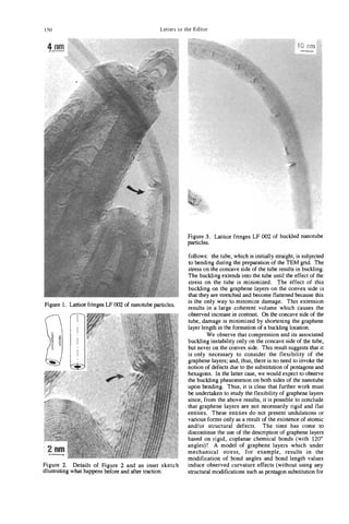


![NANBPARTICLES AND FILLED NANOCAPSULES
YAHACHI
SAITO
Department of Electrical and Electronic Engineering, Mie University, Tsu 5 14 Japan
(Received 11 October 1994; accepted in revised form 10 February 1995)
Abstract-Encapsulation of foreign materials within a hollow graphitic cage was carried out for rare-earth
and iron-group metals by using an electric arc discharge. The rare-earth metals with low vapor pressures,
Sc, Y, La, Ce, Pr, Nd, Gd, TD,Dy, Ho, Er, Tm, and Lu, were encapsulatedin the form of carbides, whereas
volatile Sm, Eu, and Yb metals were not. For iron-group metals, particles in metallic phases (a-Fe, y-Fe;
hcp-Co, fcc-Co; fcc-Ni) and in a carbide phase (M3C, M = Fe, Co, Ni) were wrapped in graphitic car-
bon. The excellent protective nature of the outer graphitic cages against oxidation of the inner materials
was demonstrated. In addition to the wrapped nanoparticles, exotic carbon materials with hollow struc-
tures, such as single-wallnanotubes, bamboo-shaped tubes, and nanochains, were produced by using tran-
sition metals as catalysts.
Key Words-Nanoparticles, nanocapsules, rare-earth elements, iron, cobalt, nickel.
1. INTRODUCTION nanotubes. When a pure graphite rod (anode) is evap-
orated in an atmosphere of noble gas, macroscopic
The carbon-arc plasma of extremely high temperatures
quantities of hollow nanoparticles and multi-wall
and the presence of an electric field near the electrodes
nanotubes are produced on the top end of a cathode.
play important roles in the formation of nanotubes[ 1,2]
When a metal-packed graphite anode is evaporated,
and nanoparticles[3]. A nanoparticle is made up of
filled nanocapsules and other exotic carbon materials
concentric layers of closed graphitic sheets, leaving a
with hollow structures (e.g., “bamboo”-shaped tubes,
nanoscale cavity in its center. Nanoparticles are also
nanochains, and single-wall (SW) tubes) are also syn-
called nanopolyhedra because of their polyhedral
thesized. Details of the preparation procedures are de-
shape, and are sometimes dubbed as nanoballs be-
scribed elsewhere[&,ll,12].
cause of their hollow structure.
When metal-loaded graphite is evaporated by arc
discharge under an inactive gas atmosphere, a wide 3. NANOPARTICLES
range of composite materials (e.g., filled nanocapsules,
Nanoparticles grow together with multi-wall nano-
single-wall tubes, and metallofullerenes, R@C82,
tubes in the inner core of a carbonaceous deposit
where R = La, Y, Sc,[4-6]) are synthesized. Nanocap-
formed on the top of the cathode. The size of nano-
sules filled with Lac, crystallites were discovered in
particles falls in a range from a few to several tens of
carbonaceous deposits grown on an electrode by
nanometers, being roughly the same as the outer di-
Ruoff et a1.[7] and Tomita et a1.[8]. Although rare-
ameters of multi-wall nanotubes. High-resolution
earth carbides are hygroscopic and readily hydrolyze
TEM (transmission electron microscopy) observations
in air, the carbides nesting in the capsules did not de-
reveal that polyhedral particles are made up of con-
grade even after a year of exposure to air. Not only
centric graphitic sheets, as shown in Fig. 1. The closed
rare-earth elements but also 3d-transition metals, such
polyhedral morphology is brought about by well-de-
as iron, cobalt, and nickel, have been encapsulated by
veloped graphitic layers that are flat except at the cor-
the arc method. Elements that are found, so far, to be
ners and edges of the polyhedra. When a pentagon is
incapsulated in graphitic cages are shown in Table 1.
introduced into a graphene sheet, the sheet curves pos-
In addition to nanocapsules filled with metals and
itively and the strain in the network structure is local-
carbides, various exotic carbon materials with hollow
ized around the pentagon. The closed graphitic cages
structures, such as single-wall (SW) tubes[9,10],
produced by the introduction of 12 pentagons will ex-
bamboo-shaped tubes, and nanachains[l 11, are pro-
hibit polyhedral shapes, at the corners of which the
duced by using transition metals as catalysts.
pentagons are located. The overall shapes of the poly-
In this paper, our present knowledge and under-
hedra depend on how the 12 pentagons are located.
standing with regard to nanoparticles, filled nanocap-
Carbon nanoparticles actually synthesized are multi-
sules, and the related carbon materials are described.
layered, like a Russian doll. Consequently, nanopar-
ticles may also be called gigantic multilayered fderenes
2. PREPARATION PROCEDURES or gigantic hyper-fullerenes[l3].
The spacings between the layers (dooz) measured by
Filled nanocapsules, as well as hollow nanoparti- selected area electron diffraction were in a range of
cles, are synthesized by the dc arc-evaporation method 0.34 to 0.35 nm[3]. X-ray diffraction (XRD) of the
that is commonly used to synthesize fullerenes and cathode deposit, including nanoparticles and nano-
153](https://image.slidesharecdn.com/13709313-carbon-nanotubes-120928071547-phpapp01/85/13709313-carbon-nanotubes-166-320.jpg)
![I54 Y. SAITO
Table 1 . Formation of filled nanocapsules. Elements in shadowed boxes are those which were encapsu-
lated so far. M and C under the chemical symbols represent that the trapped elements are in metallic and
carbide phases, respectively. Numbers above the symbols show references.
7, 8 11, 12 lJ,-!2 11,)2 I I , 12 11, 12 1 1 , I2 I I , 12 I I , 12 12 I I , 12
La Ce Pr Nd Pm Sm Eu Gd Tb Dy Ho E Tm
r Yb Lu
c c c c c c c c c c C
tubes, gave dooz = 0.344 nm[14], being consistent nally observed. The structure of the particles at this
with the result of electron diffraction. The interlayer stage may be “quasi-liquid” or amorphous with high
spacing is wider by a few percent than that of the ideal structural fluidity because of the high temperature
graphite crystal (0.3354 nm). The wide interplanar (=3500 K)[17] of the electrode and ion bombardment.
spacing is characteristic of the turbostratic graphite[ 151. Ion bombardment onto the electrode surface seems to
Figure 2 illustrates a proposed growth process[3] of be important for the growth of nanoparticles, as well
a polyhedral nanoparticle, along with a nanotube. as tubes. The voltage applied between the electrodes
First, carbon neutrals (C and C,) and ions (C+)[16] is concentrated within thin layers just above the surface
deposit, and then coagulate with each other to form of the respective electrodes because the arc plasma is
small clusters on the surface of the cathode. Through electrically conductive, and thereby little drop in volt-
an accretion of carbon atoms and coalescence between age occurs in a plasma pillar. Near a cathode, the volt-
clusters, clusters grow up to particles with the size fi- age drop of approximately 10 V occurs in a thin layer
of to lop4 cm from the electrode surface[l8].
Therefore, C + ions with an average kinetic energy
of - 10 eV bombard the carbon particles and enhance
the fluidity of particles. The kinetic energy of the car-
bon ions seems to affect the structure of deposited car-
bon. It is reported that tetrahedrally coordinated
amorphous carbon films, exhibiting mechanical prop-
erties similar to diamond, have been grown by depo-
sition of carbon ions with energies between 15 and
70 eV[191. This energy is slightly higher than the present
case, indicating that the structure of the deposited ma-
terial is sensitive to the energy of the impinging car-
bon ions.
The vapor deposition and ion bombardment onto
quasi-liquid particles will continue until the particles
are shadowed by the growth of tubes and other par-
ticles surrounding them and, then, graphitization oc-
curs. Because the cooling goes on from the surface to
the center of the particle, the graphitization initiates
on the external surface of the particle and progresses
Fig. 1 . TEM picture of a typical nanoparticle. toward its center. The internal layers grow, keeping](https://image.slidesharecdn.com/13709313-carbon-nanotubes-120928071547-phpapp01/85/13709313-carbon-nanotubes-167-320.jpg)
![Nanoparticles and filled nanocapsules 155
Fig. 2. A model of growth processes for (a) a hollow nanoparticle and, (b) a nanotube; curved lines depicted
around the tube tip show schematically equal potential surfaces.
their planes parallel to the external layer. The flat whole particle is greater for the stuffed nanocapsules
planes of the particle consist of nets of six-member than that for hollow nanoparticles. While the inner
rings, while five-member rings may be located at the -
space within a hollow nanoparticle is only 1070 of the
corners of the polyhedra. The closed structure contain- whole volume of the particle, that for a filled nano-
ing pentagonal rings diminishes dangling bonds and capsule is 10 to 80% of the whole volume.
lowers the total energy of a particle. Because the density The lanthanides (from La to Lu) and yttrium form
of highly graphitized carbon (= 2.2 g/cm3) is higher isomorphous dicarbides with a structure of the CaCz
than that of amorphous carbon (1.3-1.5 g/cm3), a type (body-centered tetragonal). These lanthanide
pore will be left inevitably in the center of a particle carbides are known to have conduction electrons (one
after graphitization. In fact, the corresponding cavi-
ties are observed in the centers of nanoparticles.
4. FILLED NANOCAPSULES
4.1 Rare earths
4.1.1 Structure and morphology. Most of the
rare-earth elements were encapsulated in multilayered
graphitic cages, being in the form of single-domain
carbides. The carbides encapsulated were in the phase
of RC2 (R stands for rare-earth elements) except for
Sc, for which Sc3C,[2O] was encapsulated[21].
A high-resolution TEM image of a nanocapsule en-
caging a single-domain YC2 crystallite is shown in
Fig. 3. In the outer shell, (002) fringes of graphitic lay-
ers with 0.34 nm spacing are observed and, in the core
crystallite, lattice fringes with 0.307-nm spacing due
to (002) planes of YC2 are observed. The YC2 nano-
crystal partially fills the inner space of the nanocap-
sule, leaving a cavity inside. No intermediate phase
was observed between the core crystallite and the gra-
phitic shell. The external shapes of nanocapsules were
polyhedral, like the nanoparticles discussed above,
while the volume ratio of the inner space (including Fig. 3. TEM image of a YC, crystallite encapsulated in a
the volume of a core crystallite and a cavity) to the nanocapsule.](https://image.slidesharecdn.com/13709313-carbon-nanotubes-120928071547-phpapp01/85/13709313-carbon-nanotubes-168-320.jpg)
![156 Y. SAITO
electron per formula unit, RC,)[22] (i.e., metallic
electrical properties) though they are carbides. All the
lanthanide carbides including YC, and Sc3C, are hy-
groscopic; they quickly react with water in air and 10'
hydrolyze, emanating hydrogen and acetylene. There-
fore, they usually have to be treated and stored in an
inactive gas atmosphere or oil to avoid hydrolysis.
However, the observation of intact dicarbides, even 100
after exposure to air for over a year, shows the excel- Y
lent airtight nature of nanocapsules, and supports
the hypothesis that their structure is completely closed i2
v1
a,
v1
by introducing pentagons into graphitic sheets like & 10-l
fullerenes[23]. 5
4.1.2 Correlationbetween metal volatility and
encapsulation. A glance at Table 1 shows us that F
carbon nanocapsules stuffed with metal carbides are
formed for most of the rare-earth metals, Sc, Y, La,
Ce, Pr, Nd, Gd, Tb, Dy, Ho, Er, and Lu. Both TEM
and XRD confirm the formation of encapsulated car-
bides for all the above elements. The structural and
10
morphological features described above for Y are
common to all the stuffed nanocapsules: the outer 1000 1500 2000 2500 3000
shell, being made up of concentric multilayered gra-
phitic sheets, is polyhedral, and the inner space is par- Temperature [K]
tially filled with a single-crystalline carbide. It should Fig. 4. Vapor pressure curves of rare-earth metals repro-
be noted that the carbides entrapped in nanocapsules duced from the report of Honig[24]. Elements are distin-
are those that have the highest content of carbon guished by their vapor pressures. Sm, ELI,Tm, and Yb are
among the known carbides for the respective metal. volatile, and Sc, Y, La, Ce, Pr, Nd, Gd, Tb, Dy, Ho, Er, and
Lu are non-volatile.
This finding provides an important clue to understand-
ing the growth mechanism of the filled nanocapsules
(see below).
In an XRD profile from a Tm-C deposit, a few pointed out[ 121; all the encapsulated elements belong
faint reflections that correspond to reflections from to the group of non-volatile metals, and those not en-
TmC, were observed[l2]. Owing to the scarcity of capsulated, to the group of volatile ones with only one
TmC, particles, we have not yet obtained any TEM exception, Tm.
images of nanocapsules containing TmC,. However, Although Tm is classified into the group of vola-
the observation of intact TmC, by XRD suggests that tile metals, it has the lowest vapor pressure within this
TmC, crystallites are protected in nanocapsules like group and is next to the non-volatile group. This in-
the other rare-earth carbides. termediary property of Tm in volatility may be respon-
For Sm, Eu, and Yb, on the other hand, nanocap- sible for the observation of trace amount of TmC2.
sules containing carbides were not found in the cath- The vapor pressure of Tm suggests the upper limit of
ode deposit by either TEM or XRD. To see where volatility of metals that can be encapsulated.
these elements went, the soot particles deposited on the This correlation of volatility with encapsulation
walls of the reaction chamber was investigated for Sm. suggests the importance of the vapor pressure of met-
XRD of the soot produced from Sm203/C compos- als for their encapsulation. In the synthesis of the
ite anodes showed the presence of oxide (Sm203)and stuffed nanocapsules, a metal-graphite composite was
a small amount of carbide (SmC,). TEM, on the evaporated by arc heating, and the vapor was found
other hand, revealed that Sm oxides were naked, while to deposit on the cathode surface. A growth mecha-
Sm carbides were embedded in flocks of amorphous nism for the stuffed nanocapsules (see Fig. 5 ) has been
carbon[l2]. The size of these compound particles was proposed by Saito et a1.[23] that explains the observed
in a range from 10 to 50 nm. However, no polyhedral features of the capsules. According to the model, par-
nanocapsules encaging Sm carbides were found so far. ticles of metal-carbon alloy in a liquid state are first
Figure 4 shows vapor pressure curves of rare-earth formed, and then the graphitic carbon segregates on the
metals[24], clearly showing that there is a wide gap be- surface of the particles with the decrease of tempera-
tween Tm and Dy in the vapor pressure-temperature ture. The outer graphitic carbon traps the metal-carbon
curves and that the rare-earth elements are classified alloy inside. The segregation of carbon continues un-
into two groups according to their volatility (viz., Sc, til the composition of alloy reaches RC2 (R = Y,
Y, La, Ce, Pr, Nd, Gd, Tb, Dy, Ho, Er, and Lu, La, ..., Lu) or Sc2C3,which equilibrates with graph-
non-volatile elements, and Sm, Eu, Tm, and Yb, vol- ite. The co-deposition of metal and carbon atoms on
atile elements). Good correlation between the volatil- the cathode surface is indispensable for the formation
ity and the encapsulation of metals was recently of the stuffed nanocapsules. However, because the](https://image.slidesharecdn.com/13709313-carbon-nanotubes-120928071547-phpapp01/85/13709313-carbon-nanotubes-169-320.jpg)
![Nanoparticles and filled nanocapsules 157
(a) (b) (C)
Fig. 5 . A growth model of a nanocapsule partially filled with
a crystallite of rare-earth carbide (RC, for R = Y, La, . . . ,
Lu; R,C, for R = Sc): (a) R-C alloy particles, which may be
in a liquid or quasi-liquid phase, are formed on the surface
of a cathode; (b) solidification (graphitization) begins from
the surface of a particle, and R-enriched liquid is left inside;
(c) graphite cage outside equilibrates with RC, (or R3C4for
R = Sc) inside.
temperature of the cathode surface is as high as 3500
K, volatile metals do not deposit on a surface of such
a high temperature, or else they re-evaporate imme-
diately after they deposit. Alternatively, since the
shank of an anode (away from the arc gap) is heated
to a rather high temperature (e.g., 2000 K), volatile
Fig. 6 . TEM picture of an a-Fe particle grown in the cath-
metals packed in the anode rod may evaporate from
ode soot; the core crystallite is wrapped in graphitic carbon.
the shank into a gas phase before the metals are ex-
posed to the high-temperature arc. For Sm, which was
not encapsulated, its vapor pressure reaches as high
as 1 atmosphere at 2000 K (see Fig. 4 . ) sists of several to about 30 graphene layers[28]. Nano-
The criterion based on the vapor pressure holds for capsules of the iron-group metals (Fe, Co, Ni) show
actinide; Th and U, being non-volatile (their vapor structures and morphology different from those of
pressures are much lower than La), were recently found rare-earth elements in the following ways. First, most
to be encapsulated in a form of dicarbide, ThC2[25] of the core crystallites are in ordinary metallic phases
and UC2[26], like lanthanide. (Le., carbides are minor). The a-Fe, P(fcc)-Co and
It should be noted that rare-earth elements that fcc-Ni are the major phases for the respective metals,
form metallofullerenes[27] coincide with those that are and small amounts of y(fcc)-Fe and a(hcp)-Co are
encapsulated in nanocapsules. At present, it is not clear also formed[ll]. Carbides formed for the three met-
whether the good correlation between the metal vol- als were of the cementite phase (viz., Fe3C, Co3C,
atility and the encapsulation found for both nanocap- and Ni3C). The quantity of carbides formed depends
sules and metallofullerenes is simply a result of kinetics on the affinity of the metal toward carbon; iron forms
of vapor condensation, or reflects thermodynamic sta- the carbide most abundantly (about 20% of metal at-
bility. From the viewpoint of formation kinetics, to oms are in the carbide phase)[29], nickel forms the
form precursor clusters (transient clusters comprising least amount (on the order of lOro), and cobalt, inter-
carbon and metal atoms) of filled nanocapsules or me- mediate between iron and nickel.
tallofullerenes, metal and carbon have to condense si- Secondly, the outer graphitic layers tightly sur-
multaneously in a spatial region within an arc-reactor round the core crystallites without a gap for most of
vessel (i.e., the two regions where metal and carbon the particles, in contrast to the nanocapsules of rare-
condense have to overlap with each other spatially and earth carbides, for which the capsules are polyhedral
chronologically). If a metal is volatile and its vapor and have a cavity inside. The graphite layers wrapping
pressure is too high compared with that of carbon, the iron (cobalt and nickel) particles bend to follow the
metal vapor hardly condenses on the cathode or near curvature of the surface of a core crystallite. The gra-
the arc plasma region. Instead, it diffuses far away phitic sheets, for the most part, seem to be stacked
from the region where carbon condenses and, thereby, parallel to each other one by one, but defect-like con-
the formation of mixed precursor clusters scarcely trast suggesting dislocations, was observed[28], indi-
occurs. cating that the outer carbon shell is made up of small
domains of graphitic carbon stacked parallel to the
4.2 Iron-group metals (Fe, Co, N ) i surface of the core particle. The structure may be sim-
4.2.1 Wrapped nanocrystals. Metal crystallites ilar to that of graphitized carbon blacks, being com-
covered with well-developed graphitic layers are found posed of small segments of graphitic sheets stacked
in soot-like material deposited on the outer surface of roughly parallel to the particle surface[30].
a cathode slag. Figure 6 shows a TEM picture of an Magnetic properties of iron nanocrystals nested in
a(bcc)-Fe particle grown in the cathode soot. Gener- carbon cages, which grew on the cathode deposit,
ally, iron crystallites in the a-Fe phase are faceted. The have been studied by Hiura et al. [29]. Magnetization
outer shell is uniform in thickness, and it usually con- ( M - H )curves showed that the coercive force, H,, of](https://image.slidesharecdn.com/13709313-carbon-nanotubes-120928071547-phpapp01/85/13709313-carbon-nanotubes-170-320.jpg)
![158 Y. SAITO
this nanoscale encapsulated material at room temper- are nearly spherical in shape and are embedded in
ature is about 80 Oe, larger than that of bulk a-Fe amorphous carbon globules. For some iron particles,
(H, = 1 Oe). The particle sizes of iron studied (10 to lattice fringes (0.34-0.35 nm spacing) suggesting the
1 0 0 nm) and the large coercive force suggests that the presence of a few layers of graphene sheets between
magnetization process is dominated by the coopera- their surface and the outer amorphous carbon are ob-
tive spin rotation of single domains. The saturation served, as indicated by arrows. The iron is predomi-
magnetization was 25 emu/g, being smaller than that nantly in a-Fe phase, and minorities are in y-Fe and
for pure a-Fe (221.7 emu/g) because the measured Fe3C phases. The iron particles in the chamber soot
sample contains a large amount of free carbon as well are smaller (3-10 nm) than those in the cathode soot.
as wrapping graphite. For application, magnetic par- Much higher coercive force of 380 Oe and superpara-
ticles have to be extracted, and it is also necessary to magnetism were observed for the smaller iron nano-
control the size and composition of iron particles to crystals grown in the chamber soot[31].
obtain larger coercive force and magnetization. Majetich and coworkers have studied magnetic
Iron, cobalt, and nickel particles also grow in soot properties of carbon-coated Co[32], Gd2C3, and
deposited on the chamber walls, but graphitic layers Ho& nanocrystals[33] formed in the chamber soot.
wrapping the metals are not so well-developed as those A brief account on the coated Co nanocrystals is given
grown in the cathode soot. Figure 7 shows a TEM pic- here. They extracted magnetic nanocrystals from the
ture of iron particles grown in the chamber soot. They crude soot with a magnetic gradient field technique.
Fig. 7. TEM picture of iron nanocrystals collected from the chamber soot; nanocrystals are embedded
in amorphous carbon globules. On the surface of some core crystals, a few fringes with 0.34-0.35 nm spacing
suggesting the presence of graphitic layers are observed, as indicated by arrows.](https://image.slidesharecdn.com/13709313-carbon-nanotubes-120928071547-phpapp01/85/13709313-carbon-nanotubes-171-320.jpg)
![Nanoparticles and filled nanocapsules 159
Fig. 8. TEM picture of a bamboo-shaped carbon tube.
The majority of Co nanocrystals (in the fcc phase) ex- lengthening of tubes goes on intermittently for the
ist as nominally spherical particles with a 0.5-5 nm in bamboo-shaped tubes, while the pyrolytic fibers grow
radius. Hysteretic and temperature-dependent mag- continuously.
netic response, in randomly and magnetically aligned A piece of Ni metal was sometimes left in a com-
powder samples frozen in epoxy, revealed fine particle partment located in the middle of a bamboo tube, as
magnetism associated with single-domain Co particles. shown in Fig. 10. The shape of the trapped metal is
These single-domain particles exhibited superparamag- reminiscent of a drop of mercury left inside a glass
netic response with magnetic hysteresis observed only capillary. The contact angle between the Ni metal and
at temperatures below Ts (blocking temperature) = the inner wall of graphite is larger than 90”(measured
160 K. angle is about 140”), indicating that the metal poorly
4.2.2 Bamboo-shaped tubes. A carbon tube wets the tube walls. Strong capillary action, antici-
with a peculiar shape looking like “bamboo,” pro- pated in nanometer-sized cavities[36,37], does not
duced by the arc evaporation of nickel-loaded graph- seem to be enough to suck the metal into the tubes,
ite, is shown in Fig. 8. The tube consists of a linear at least for the present system[ll,38].
chain of hollow compartments that are spaced at nearly 4.2.3 Nanochains. Figure 11 shows a TEM pic-
equal separation from 50 to 100nm. The outer diameter ture of nanochains produced from a Ni/C composite
of the bamboo tubes is about 40 nm, and the length anode[ll]. The nanochains consist of spherical, hol-
typically several pm. One end of the tube is capped low graphitic particles with outer diameters of 10-20 nm
with a needle-shaped nickel particle which is in the and inner diameters of several to 10 nm. A nanochain
normal fcc phase, and the other end is empty. Walls comprises a few tens of hollow particles that are linearly
of each compartment are made up by about 20 gra- connected with each other. The inside of some parti-
phitic layers[34]. The shape of each compartment is cles is filled with a Ni particle, as seen in the figure.
quite similar to the needle-shape of the Ni particle at The morphology of each particle resembles that of
the tip, suggesting that the Ni particle was once at the graphitized carbon blacks, which are made up of many
cavities. patches of small graphitic sheets piling up to form
Figure 9 illustrates a growth process of the bamboo spherical shapes.
tubes. It is not clear whether the Ni particle at the tip The chains of hollow carbon may be initially chains
was liquid or solid during the growth of the tube. We consisting of Ni (or carbide) particles covered with gra-
infer that the cone-shaped Ni was always at the tip and phitic carbon. The chains lying on the hot surface of the
it was absorbing carbon vapor. The dissolved carbon cathode are heated, and Ni atoms evaporate through
diffused into the bottom of the Ni needle, and carbon defects of the outer graphitic carbon because the va-
segregated as graphite at the bottom and the side of por pressure of Ni is much higher than carbon. Thus,
the needle. After graphitic layers (about 20 layers) the carbon left forms hollow graphitic layers.
were formed, the Ni particle probably jumped out of Seraphin el al.[39] reported that an arc evaporation
the graphitic sheath to the top of the tube. The mo- of Fe/C composite anode also generated nanochains
tive force of pushing out the Ni needle may be a stress with similar morphology, described above.
accumulated in the graphitic sheath due to the segre- 4.2.4 Single-wall tubes. Following the synthe-
gation of carbon from the inside of the sheath. sis studies of stuffed nanocapsules, single-wall (SW)
The segregation process of graphite on the surface tubes were discovered in 1993[9,10]. SW tubes are
of a metal particle is similar to that proposed by Ober- found in chamber soot when iron[9] and cobalt[lO]
lin and Endo[35] for carbon fibers prepared by ther- were used as catalysts, and for nickel[11,401 they grow
mal decomposition of hydrocarbons. However, the on the surface of the cathode slag. For iron catalyst,
Fig. 9. Growth model of a bamboo tube.](https://image.slidesharecdn.com/13709313-carbon-nanotubes-120928071547-phpapp01/85/13709313-carbon-nanotubes-172-320.jpg)
![160 Y. SAITO
Fig. 10. TEM picture of a Ni metal left in the capillary of a graphite tube. Contact angle of the Ni particle
on graphite surface (angle between the Ni/graphite interface and the Ni free surface) is larger than 90"
(measured angle is about 140"), indicating poor wetting of Ni on the inner wall of a graphite tube.
methane is reportedly an indispensable ingredient to Effects of various combinations of 3d-transition
be added to an inactive gas (Ar for iron)[9]. For co- metals on the formation of SW tubes have been stud-
balt and nickel, on the other hand, no additives are ied by Seraphin and Zhou[41]. They reported that
necessary; the arc evaporation of metal-loaded graph- mixed metals enhanced the production of SW tubes;
ite in a pure inactive gas (usually He) produces SW in particular, a 50% Fe + 50% Ni combination per-
tubes. Figure 12 shows a TEM image of bundles of formed much better than Fe, Co, or Ni alone. It was
SW tubes growing radially from a Ni-carbide particle. also shown that the addition of some metals, such as
The diameter of tubes are mostly in a range from Cu, to these metals poisoned their catalytic action.
1.0 nm to 1.3 nm. Tips of SW tubes are capped and Catalysts for SW tube formation are not confined
hollow inside. No contrast suggesting the presence of to the iron-group metals. Some elements of the lan-
Ni clusters or particles is observed at the tips. thanide series can catalyze the formation of SW tubes,
Fig. 11. TEM picture of nanochains.](https://image.slidesharecdn.com/13709313-carbon-nanotubes-120928071547-phpapp01/85/13709313-carbon-nanotubes-173-320.jpg)
![Nanoparticles and filled nanocapsules 161
Fig. 12. TEM picture of single-wall tubes growing radially from a Ni-carbide particle.
as has been exemplified for Gd[42], Y[43], La[44] and suggests the possibility of producing SW tubes with
Ce[45]. The morphology of the tubes that grow radi- any desirable diameter.
ally from these metal (or compound) particles and A hypothetical growth process[40] of SW tubes
have “sea urchin”-like morphology is similar to that from a core particle is illustrated in Fig. 13. When
shown for Ni, but the length of tubes is shorter for the metal catalyst is evaporated together with carbon by
lanthanides (-100 nm long) than that of Ni (-pm arc discharge, carbon and metal atoms condense and
long). The diameter of tubes produced from La is typ- form alloy (or binary mixed) particles. As the particles
ically 1.8-2.1 nm, being larger (about twice) than that are cooled, carbon dissolved in the particles segregates
for Ni. It is reported that the addition of sulfur to Co onto the surface because the solubility of carbon de-
catalyst promotes the formation of thicker SW tubes creases with the decrease of temperature. Some singu-
(in a range from 1 to 6 nm in diameter)[46]. The de- lar surface structures or compositions in an atomic
pendence of tube diameter on the catalysts employed scale may catalyze the formation of SW tubes. After
the nuclei of SW tubes are formed, carbon may be
supplied from the core particle to the roots of SW
tubes, and the tubes grow longer, maintaining hollow
capped tips. Addition of carbon atoms (and C,) from
the gas phase to the tips of the tubes may also help the
growth of tubes.
4.3 Anti-oxidation of wrapped
iron nanocrystals
(a) (b) (C) The protective nature of graphitic carbon against
oxidation of core nanocrystals was demonstrated by
Fig. 13. Hypothetical growth process of SW tubes from a an environmental test (80°C, 85% relative humidity,
metal/carbon alloy particle: (a) segregation of carbon toward
the surface, (b) nucleation of SW tubes on the particle sur- 7 days)[44]. Even after this test, XRD profiles revealed
face and, (c) growth of the SW tubes. that the capsulated iron particles were not oxidized at](https://image.slidesharecdn.com/13709313-carbon-nanotubes-120928071547-phpapp01/85/13709313-carbon-nanotubes-174-320.jpg)
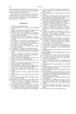
![ONION-LIKE GRAPHITIC PARTICLES
D. UGARTE
Laboratorio National de Luz Sincrotron (CNPq/MCT), Cx. Postal 6192,
13081-970 Campinas SP, Brazil;
Institut de Physique Experimentale, Ecole Polytechnique FCdCrale de Lausanne,
1015 Lausanne, Switzerland
(Received 18 July 1994; accepted 10 February 1995)
Abstract-Nanometric graphitic structures (fullerenes, nanotubes, bucky-onions, etc.) form in different
harsh environments (electric arc, electron irradiation, plasma torch). In particular, the onion-like graphitic
particles may display a wide range of structures, going from polyhedral to nearly spherical. High-resolution
electron microscopy is the primary tool for studying these systems. On the basis of HREM observations,
we discuss the energetics and possible formation mechanism of these multi-shell fullerenes. The better un-
derstanding of the underlying processes would allow the development of an efficient production method.
Key Words-Graphite, fullerenes, HREM, nanostructures, electron irradiation.
1. INTRODUCTION large-scale synthesis of nanotubes[4]. The central part
of the deposit consists of a black powder containing
The high melting temperature of carbon materials
a mixture of graphitic nanotubes and nanoparticles.
(=4000”K) has made difficult the preparation and
Although this procedure allows the generation of these
study of carbon clusters. In recent years, the field of
particles in macroscopic quantities, the purification of
nanometric carbon particles has found an unexpected
the different soot components (e.g., nanotubes) has
and overwhelming development. In a first step, the so-
not been easily performed. Centrifugation and filtra-
phisticated laser evaporation source revealed the ex-
tion methods have been unsuccessful, and a rather in-
istence of fullerenes, but with the limitation that their
efficient oxidation procedure (99% of the material is
study could only be performed in cluster-beam exper-
lost) has allowed the production of purified nanotubes
, iments[l]. Second, in 1990, the current and simple
samples[l2].
electric arc-discharge[2] allowed the synthesis and
The electric arc is a transient phenomenon, where
study of these molecules by a large number of labo-
the region of the electrode producing the arc changes
ratories, generating a burst of revolutionary discov-
permanently all over the surface of contact. The gen-
eries. A wide family of nanometric graphitic systems
erated temperature gradients induce an important
may be synthesized by making slight modifications to
range of conditions for the formation of graphitic
the electric arc experiment (nanotubes[3,4], nanopar-
nanoparticles; this fact leads to wide size and shape
ticles[5-7], metal-filled nanoparticles[8-10], etc.).
distributions (see Fig. la). The particles usually display
High-resolution transmission electron microscopy
a clear polyhedral morphology, and a large inner empty
(HREM) is the technique best suited for the structural space (3-10 nm in diameter). Macroscopic quantities
characterization of nanometer-sized graphitic parti- of nanometric graphitic particles may be obtained by
cles. In-situ processing of fullerene-related structures a thermal treatment of “fullerene black”[ 13,141; this
may be performed, and it has been shown that carbo- method yields particles with similar structure to those
naceous materials transform themseIves into quasi- ones generated in the arc, but with a narrower size dis-
spherical onion-like graphitic particles under the effect
tribution, in particular located in the 5 1 0 nm range.
of intense electron irradiation[ll]. The high-energy electron irradiation of carbona-
in this paper, we analyze the methods of synthesiz- ceous materials produces remarkably symmetrical and
ing multi-shell fullerene structures and try to gather spherical onion-like particles[ll] (see Fig. lb, 2). These
some information about their formation mechanism. particles are very stable under electron bombardment,
We also discuss some particularities of the energetics even when formed by a small number of shells (2-4)
of onion-like graphitic particles. The understanding of [15]. The generation of these quasi-spherical graphitic
the parameters involved would allow the development systems (nicknamed bucky-onions) is realized in situ in
of efficient production procedures. an electron microscope. However, the particles are only
formed in minute quantities on an electron microscopy
2. SYNTHESIS OF MULTI-SHELL FULLERENES
grid, and their study may only be performed by trans-
mission electron microscopy-associated techniques.
The electric arc is the easiest and most frequently Two major structural aspects differentiate them from
used experiment to produce onion-like particles. A the graphitic particles discussed previously: (a) the
dc arc-discharge is used to generate a carbon deposit shape of the concentrical arrangement of graphitic lay-
on the negative electrode following the procedure for ers is a nearly perfect sphere, (b) the innermost shell
163](https://image.slidesharecdn.com/13709313-carbon-nanotubes-120928071547-phpapp01/85/13709313-carbon-nanotubes-176-320.jpg)
![164 D. UGARTE
i
Fig. 1. High-resolution electron micrographs of graphitic particles: (a) as obtained from the electric arc
deposit, they display a well-defined faceted structure and a large inner hollow space, (b) the same parti-
cles after being subjected to intense electron irradiation (note the remarkable spherical shape and the dis-
appearance of the central empty space); dark lines represent graphitic layers.
is always very small, displaying a size very close to in the 0.2-1 pm range, (b) small particles (<0.2 pm)
C60 (20.7-1 nm) (see Fig. 2). also spherical in shape, but formed by concentric gra-
Onion-like graphitic clusters have also been gener- phitic layers. Unfortunately, no detailed HREM study
ated by other methods: (a) shock-wave treatment of of these particles was undertaken, but an apparent
carbon soot[l6]; (b) carbon deposits generated in a size effect connecting diamond and graphitic particles
plasma torch[l7], (c) laser melting of carbon within was insinuated. Recently, an interesting experiment
a high-pressure cell (50-300 kbar)[l8]. For these three also revealed a relation between ultradispersed dia-
cases, the reported graphitic particles display a sphe- monds (3-6 nm in diameter) and onion-like graphitic
roidal shape. particles. The nanometer diamond sample was obtained
In particular, the laser melting experiment produced by a chemical purification of detonation soot. The an-
two well-differentiated populations of carbon clusters: nealing treatment (1100-1 500°C) of nanodiamonds
(a) spheroidal diamond particles with a radial texture generates onion-like graphitic particles with a remark-](https://image.slidesharecdn.com/13709313-carbon-nanotubes-120928071547-phpapp01/85/13709313-carbon-nanotubes-177-320.jpg)
![Onion-like graphitic particles 165
is an example of the graphitization of a "hard carbon"
(when subjected to heat treatment, it yields irregularly
shaped pores or particles instead of extended flat gra-
phitic planes)[14,21].
In the case of carbon melting experiments[l6] and
electric arc[5,6], it has been suggested that the onion-
like particles are generated by the graphitization of a
liquid carbon drop. The growth of graphite layers is
supposed to begin at the surface and progress toward
the center (see Fig. 3a-d). Saito et d [ 7 ] has suggested
a similar mechanism but, instead of liquid carbon,
they considered a certain carbon volume on the elec-
trode surface, which possesses a high degree of struc-
tural fluidity due to the He ion bombardment.
The progressive ordering from the surface to the
center has been experimentally observed in the case of
the electron irradiation-induced formation of the
quasi-spherical onion-like particles[25]. In this case,
the large inner hollow space is unstable under electron
Fig. 2. HREM image of a quasi-sphericalonion-like graphitic bombardment, and a compact particle (innermost shell
particles generated by electron irradiation (dark lines repre- 4 6 0 ) is the final result of the graphitization of the
sent graphitic shells, and distance between layers is 0.34 nm). carbon volume (see Fig. 3e-h).
The large inner hollow space observed in polyhe-
dral particles is supposed to be due to the fact that
able spheroidal shape[l9], and a compact structure the initial density of the carbon volume (drop) is lower
very similar to the bucky-onions generated by electron than graphite[7]. Then, in order to prepare more
irradiation[111. compact graphitic particles (smaller inner shell), the
starting carbon phase should have a density closer
to graphite (2.25 gr/cm2). This basic hypothesis has
3. FORMATION MECHANISM
been confirmed by subjecting nanodiamonds to a
In the preceding section, we have described differ- high-temperature treatment (diamond is much denser
ent experiments generating graphitic nanoparticles. As than graphite, 3.56 gr/cm2)[ 191. Experimentally, it
for the case of fullerene synthesis, the procedures are has been observed that the formation of graphitic
rather violent (electric arc, plasma torch, shock waves, layers begins at the (1 11) diamond facets, then gener-
high-temperature treatment, electron irradiation, etc.) ates closed-surface graphitic layers, and subsequently
and clearly display the present incapacity of generat- follows the formation of concentric shells epitaxially
ing nanometric curved and closed graphitic systems by towards the center. At an intermediate stage, the onion-
standard chemical techniques. For the synthesis of like graphitic particles contain a tiny diamond core
c 0 it has been found that a temperature on the or-
6, (see Fig. 2 in ref. [19]). This process yields carbon on-
der of or higher than 1200°C are necessary to anneal
the carbon clusters in the gas phase and efficiently
form Cso molecules[20]. In the case of the graphitiza-
tion process, the dewrinkling and elimination of de-
fects in graphitic layers begins at 2O0OoC[21]. The
extremely stable carbon-carbon bonds are responsible
for the high-energetic process necessary to anneal gra-
phitic structures. a b C d
The formation mechanism of fullerenes and related
structures is not well understood. The fascinating high
aspect ratio of nanotubes is associated to the electric
field of the arc[7,22], but this fact has not yet been
confirmed and/or been applied to control their growth. f h
Moreover, the arc process generates simultaneously a
large quantity of polyhedral graphic particles. The for- Fig. 3. Schematic illustration of the growth process of a
mation of multi-shell graphitic particles from the gas graphitic particle: (a)-(d) polyhedral particle formed on the
phase by a spiral growth mechanism has also been sug- electric arc; (d)-(h) transformation of a polyhedral particle
gested[23,24], but no convincing experimental data of into a quasi-spherical onion-like particle under the effect of
high-energy electron irradiation; in (f) the particle collapses
a spiral structure has been reported. and eliminates the inner empty space[25]. In both schemes,
The thermal treatment of fullerene black generates the formation of graphite layers begins at the surface and
nanometric polyhedral particles[ 131. This experiment progresses towards the center.](https://image.slidesharecdn.com/13709313-carbon-nanotubes-120928071547-phpapp01/85/13709313-carbon-nanotubes-178-320.jpg)
![166 D. UGARTE
ions with a very small inner empty space, which con- 5 hexagons (non-planar structure with a bowl shape)
trasts with the polyhedral particles prepared by heat is a very floppy structure. This molecule is the basic
treatment of fullerene black[l3]. unit of C60,and also the atomic arrangement present
at the corners of faceted giant fullerenes. It has been
observed by NMR that, at room temperature, it spon-
4. ENERGETICS
taneously presents a bowl inversion transition, with an
The elimination of the energetic dangling bonds energy barrier of only 440 meV[321. Then, we may use
present at the edges of a tiny graphite sheet is supposed this value to get a bare estimation of the energy nec-
to be the driving force to induce curvature and closure essary to crash the 12 corners of a polyhedral graphitic
in fullerenes; this phenomenon is also associated with cage (containing the corannulene configuration) into
the formation of larger systems, such as nanotubes a spherical one, and it turns out to be of the same
and graphitic particles. order of magnitude that the gain in van der Waals
The remarkable stability of onion-like particles[l5] energy mentioned previously (=5 eV). This fact in-
suggests that single-shell graphitic molecules (giant ful- dicates that a global evaluation of multi-shell struc-
lerenes) containing thousands of atoms are unstable tures should be performed to answer the question of
and would collapse to form multi-layer particles; in the minimal energy structure of onion-like graphitic
this way the system is stabilized by the energy gain particles.
from the van der Waals interaction between shells From a different point of view, the sphericity of the
[ 15,26,27]. irradiation generated onion-like particles have also
Graphite is the most stable form of carbon at am- been attributed to imperfect shells with a large num-
bient conditions, and it is formed by the stacking of ber of defects[33].
planar layers. The extreme robustness of the concen- Concerning the possible arrangement of concentric
tric arrangement of spherical fullerenes led to the hy- defect-free graphitic cages, a polyhedral graphitic par-
pothesis that the quasi-spherical onion-like graphitic ticle has all the shells in the same orientation, so that
particles are the most stable form of carbon parti- all the comers (pentagons) are perfectly superimposed
cles[l5]. This controversy between planar configura- (see Fig. 4a). If the pentagons of the concentric shells
tion of the sp2 bonding in macroscopic graphite and are not aligned, the final shape of graphitic particles
the apparent spherical shape in nanometric system, has should be much closer to a sphere. In the spherical
attracted a great deal of interest[28]. Calculations of particles, an interesting issue is the fact that the shells
the structure of giant fullerenes are not able to give a may be rotating relative to each other[l5]. This behav-
definitive answer: (a) models based on elastic or em- ior has been predicted for C60 in C240[30]and for
pirical potentials predict that the minimal energy struc- multi-shell tubes[34].
ture is a slightly relaxed icosahedron with planar
facets, the curvature being concentrated at the corner
of the polyhedron (pentagons)[26,29,30]]; (b) ab ini- 5. SUMMARY AND PERSPECTIVES
tio calculations predict two local energy minima for The multi-shell fullerenes constitute the transition
C240. One represents a faceted icosahedron, and the from fullerenes to macroscopic graphite. They present
second, a nearly spherical structure distributing the both the closed graphitic surface of fullerenes and the
strain over all atoms, is slightly more stable (binding stacked layers interacting by van der Waals forces, as
energy per atom -7.00 and -7.07 eV for polyhedral in graphite.
and spherical fullerenes)[311. One of the main scientific issues of the discovery
When using these theoretical results to analyze of the bucky-onions is the unresolved question of min-
onion-like particles, we must take into account that imal energy configuration of carbon clusters (onion-
calculations are performed for single graphitic shells,
which are subsequently arranged concentrically and,
then, conclusions are obtained about the minimal en-
ergy configuration. This fact arises from the limited
number of atoms that may be included in a calcula-
tion due to present computational capabilities (the
smallest onion-like particles are formed by Cso in a
C240 and this system represents 300 atoms).
The inter-layer interaction (EvdW, der Waals
van
energy) is usually added at the end, and then it does
not participate in the energy minimization. Evaluating
inter-shell interaction by a simple Lennard-Jones pair
potential shows that concentrical spherical shells are P S
more stable than icosahedral ones (EvdW between C240
and C540 is -17.7 and -12.3 eV for spherical and
Fig. 4 Onion-like graphitic particles formed by three con-
.
icosahedral shells, respectively). An interesting com- centric layers (C,,,, Cm, &: ,) polyhedral (marked P) and
parison may be performed by considering that coran- spherical (marked S) structures. For clarity, only a half part
nulene CzoHlo, which is a pentagon surrounded by of each shell is shown.](https://image.slidesharecdn.com/13709313-carbon-nanotubes-120928071547-phpapp01/85/13709313-carbon-nanotubes-179-320.jpg)
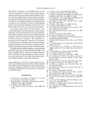

![METAL-COATED FULLERENES
U. ZIMMERMANN, MALINOWSKI," BURKHARDT, T. P. MARTIN
N. A. and
Max-Planck-Institut fur Festkorperforschung, Heisenbergstr. 1, 70569 Stuttgart, Germany
(Received 24 October 1994; accepted 10 February 1995)
Abstract-Clusters of c 6 0 and C,, coated with alkali or alkaline earth metals are investigated using photo-
ionization time-of-flight mass spectrometry. Intensity anomalies in the mass spectra of clusters with com-
position C,M, and C70Mx = 0. . .500; M E f Ca, Sr, Bal) seem to be caused by the completion of
(x
distinct metal layers around a central fullerene molecule. The first layer around Cs0 or C,o contains 32
or 37 atoms, respectively, equal to the number of carbon rings constituting the fullerene cage. Unlike the
alkaline earth metal-coated fullerenes, the electronic rather than the geometric configuration seems to be
the factor determining the stability of clusters with composition (c60)"Mx and (C70),M,, M E (Li, Na,
K, Rb, Cs]. The units CsoM, and C70M6 found t o be particularly stable building blocks of the clus-
are
ters. At higher alkali metal coverage, metal-metal bonding and an electronic shell structure appear. An
exception was found for C60Li12, which is very stable independently of charge. Semiempirical quantum
chemical calculations support that the geometric arrangement of atoms is responsible for the stability in
this case.
Key Words-Fullerenes, mass spectrometry, clusters, electronic shells, icosahedral layers.
1. INTRODUCTION each time a new layer of metal atoms has been com-
pleted around a central fullerene molecule, the stabil-
In their bulk intercalation phase compounds of c0 6
ity of these clusters seeming to be purely geometric in
and alkali or alkaline earth metals have been studied
origin. The first layer contains exactly the same num-
intensively, spurred particularly by the discovery of su-
ber of metal atoms as there are rings in the fullerene
perconductivity in several of these metal fullerides,
cage. In growing additional layers, the metal might be
such as C6&, cs0Rb3, C60Ca,, etc.[l-5]. However,
expected to prefer the icosahedral shell structure ob-
despite the wealth of information that could yet be ex-
served in pure alkaline earth cIusters[lO,l I]. However,
tracted from these fullerene compounds, we would still
our measurements suggest a different growth pattern.
like to return briefly to looking at some interesting ex-
Coating the fullerenes with alkali metals (section 4),
periments that can be done by bringing just one sin-
the resulting structures seem to be primarily governed
gle fullerene molecule in contact with atoms of the
by the electronic configuration. For example, the
metals commonly used for the doping bulk fullerite.
charge transfer of up to 6 electrons to the lowest un-
The properties of these very small metal-fullerene sys-
occupied molecular orbital (LUMO) of C60observed
tems then termed clusters, can be studied quite nicely
in bulk alkali fullerides[5] is also observed in our ex-
in the gas phase[6]. We observed that, in the gas phase,
periments, leading to the very stable building block
such a single fullerene molecule can be coated with lay-
C&& for clusters, where M is any alkali metal. An
ers of various alkali and alkaline earth metals[7,8]. In
exception to this is the cluster C60Li12. Supported by
lhis contribution, we will focus primarily on the struc-
semiempirical quantum chemical calculations, we find
ture, both electronic and geometric, of this metal coat-
the high stability of C60Li,2to be caused by the geo-
ing of the fullerenes c 6 0 and C70.
metric arrangement of the metal atoms rather than by
The method we use to study these metal-fullerene
the electronic configuration[l2]. As predicted by ab
clusters is photoionization time-of-flight mass spec-
initio calculations, this arrangement most likely has
trometry (section 2 ) . The clusters are produced by
perfect icosahedral symmetry[ 131. At higher alkali
coevaporation of fullerenes and metal in a gas aggre-
metal coverage, the coating becomes increasingly me-
gation cell. By ionizing and, in some cases, heating the
tallic and an oscillating structure caused by the suc-
clusters with a pulsed laser, various features appear in
cessive filling of electronic shells shows up in the mass
the mass spectra that contain the information neces- spectra, if photon energies near the ionization thresh-
sary to suggest a geometric or electronic configuration old are used.
for the cluster investigated.
Note that we always speak of c0 and C70as a moi-
6
When building clusters by coating the fullerenes
ecule and not a cluster. We reserve the word 'cluster'
with metal, features similar to the electronic and geo-
to refer to units composed of several fullerenes and
metric shells found in pure metal clusters[9] are ob-
metal atoms.
served in the mass spectra. In the case of fullerene
molecules coated with alkaline earth metals (section 3),
we find that a particularly stable structure is formed 2. EXPERIMENTAL
*Permanent address: Central Laboratory of Photopro- Figure 1 shows a schematic representation of the
cesses, Bulgarian Academy of Sciences, 1040 Sofia, Bulgaria. experimental setup used to study the metal-fullerene
169](https://image.slidesharecdn.com/13709313-carbon-nanotubes-120928071547-phpapp01/85/13709313-carbon-nanotubes-182-320.jpg)
![170 U. ZIMMERMAN al.
et
a two-stage reflector and a mass resolution of better
REF than 20,000.
The size distribution of the clusters produced in the
7 cluster source is quite smooth, containing no informa-
tion about the clusters except their composition. To
obtain information about, for example, the relative
stability of clusters, it is often useful to heat the clus-
ters. Hot clusters will evaporate atoms and molecules,
preferably until a more stable cluster composition is
reached that resists further evaporation. This causes
an increase in abundance of the particularly stable spe-
C LERATIONREOlON cies (Le., enhancing the corresponding peak in the
mass spectrum, then commonly termed 'fragmentation
" spectrum'). Using sufficiently high laser fluences
CLUSTER
CONDENSATION
PUMPING
STAGE
TOF MASS
SPECIXOMETER
(=50 pJ/mm2), the clusters can be heated and ion-
CELL
ized simultaneously with one laser pulse.
Fig. 1. Experimental setup: the clusters are emitted from the
cluster condensation cell, passing as a particle beam through
3. COATING WITH ALKALINE EARTH METALS
a differential pumping stage into the focus of a time-of-flight
mass spectrometer, where they are ionized by a laser pulse. In this section, we will investigate the structure of
clusters produced when the metal oven is filled with
one of the alkaline earth metals Ca, Sr, or Ba.
clusters. The cluster source o n the left is a low- A mass spectrum of C60Bax is shown in Fig. 2.
pressure, inert gas condensation cell filled with ap- The mass peaks corresponding to singly ionized clusters
proximately 1 torr He gas and cooled by liquid nitrogen have been joined by a connecting line. Note that the
flowing through the outer walls of the cell. Inside the series of singly ionized clusters shows a very prominent
cell, two electrically heated ovens, one containing a peak at the mass corresponding to C60Ba32,implying
fullerene and one containing a metal, produce inter- that this cluster is particularly stable. In searching for
penetrating vapor clouds of the two materials. This an explanation for the high stability of this cluster, we
mixture is cooled by collisions with the He gas, thereby can obtain a first hint from looking at the doubly ion-
supersaturating the vapor and causing clusters to con- ized clusters also visible in Fig. 2 (the peaks not con-
dense. The size distribution of the clusters thus pro- nected by the line correspond to doubly ionized
duced is rather broad, but the mean composition of clusters). Again, the peak at x = 32 is particularly
the clusters depends on the relative density of the va- strong. This seems to indicate that the stability of
por components and can be adjusted by the tempera- CmBa,, is not caused by a closed-shell electronic con-
tures of the ovens. However, the range of cluster figuration. Instead, the high stability is expected to be
compositions that can be studied using mass spectrom- of geometric origin. Remembering that the total
etry is limited, despite the high resolution of the mass number of faces or rings constituting the cagelike
spectrometer employed: Due to the various natural iso- structure of the c 6 0 molecule is 32 and, thus, equal to
topes exhibited by most of the metals studied, the mass the number of Ba-atoms required to form this highly
spectra become increasingly confused with rising metal
content, making exact identification of the peaks im-
possible. For metals with more than one significant
800
isotope we can, therefore, only study clusters with ei-
ther small metal and high fullerene content or high
metal content and just one fullerene per cluster. The
formation of pure metal clusters has to be avoided for
-
:
the same reason. By keeping the temperature of the 9
metal oven below the threshold for formation of pure -3
metal clusters and introducing only small amounts of -2
Y
fullerenes as condensation seeds into the metal vapor, c
1
it is possible to generate cluster distributions consist- 8
ing almost completely of compositions C60Mx o r
C70Mxwith M E (Li, Na, K, Rb, Cs, Ca, Sr, Ba) and
0
x = o . . . 500. 1000 3000 5000 7000
After condensation, the clusters are transported by mass [amu]
the He-flow through a nozzle and a differential pump-
ing stage into a high vacuum chamber. For ionization Fig. 2. Mass spectrum of photoionized C,Ba, clusters con-
taining both singly and doubly ionized species: the solid line
of the clusters, we used excimer and dye laser pulses
connects peaks of singly ionized clusters. The sharp edge oc-
at various wavelengths. The ions were then mass an- curs at 32 metal atoms, equal to the total number of hex-
alyzed by a time-of-flight mass spectrometer, having agonal and pentagonal rings of the C60molecule.](https://image.slidesharecdn.com/13709313-carbon-nanotubes-120928071547-phpapp01/85/13709313-carbon-nanotubes-183-320.jpg)
![Metal-coated fullerenes 171
stable cluster, the arrangement of metal atoms in this
cluster becomes obvious. By placing one Ba atom onto
each of the 12 pentagons and 20 hexagons of the c 6 0
300 1
I
x = 32
molecule, a structure with full icosahedral symmetry
(point group I,,) is obtained that can be visualized as -
104
an almost close-packed layer of 32 Ba-atoms coating
the c60 molecule. It seems reasonable that this struc-
ture exhibits an unusually high stability, somewhat
similar to the geometric shells observed in pure alka-
line earth clusters[lO,l I]. Any additional metal atoms
situated on this first metal layer are likely to be only
weakly bound to the layer underneath and, thus, evap-
orate easily, causing the mass peaks of C60Baxwith x
greater than 32 to disappear almost completely. The
small peaks at x = 35,38, and 43 might signal the com-
pl’etionof small stable metal islands on the first metal
layer. We can, however, presently only speculate on
the nature of these minor structures.
For a rough estimate of the packing density of this
first metal layer, assume the atoms to be hard spheres
having the covalent radii of the respectiveatoms (0.77 A
for C; 1.98 A for Ba[14]). Placing the carbon spheres 0 50 100 130
at the appropriate sites of the Cm structure with bond X
lengths 1.40-4and 1.45 A[ 151 and letting the Ba spheres
rest on the rings formed by the carbon atoms, the Ba Fig. 3. Mass spectra of photoionized C,,Ca; (top) and
spheres placed on neighboring hexagons will almost C7&a: (bottom): the lower axis is labeled by the number of
metal atoms on the fullerene molecule. The peaks at x = 32
touch, spheres on neighboring pentagons and hexa- for CmCa, and x = 37 for C&a, correspond to a first
gons will overlap by a few tenths of an h g s t r ~ m The . metal layer around the fullerenes with one atom located at
distance of the metal atoms to the center of the mol- each of the rings. The edges at x = 104 and x = 114, respec-
ecule is almost equal for atoms on hexagonal and pen- tively, signal the completion of a second metal layer.
tagonal faces. In this simple picture, the packing of
the metal layer is almost perfectly dense, the Ba atoms
having an appropriate size. Incidentally, this argument trum in Fig. 2 but with a higher metal vapor density.
also holds in a similar manner for Sr- and Ca-atoms. A slight background caused by fragmentation of clus-
Of course, this simple picture constitutes only a ters inside the drift tube of the mass spectrometer has
crude approximation and should be valued only for been subtracted. The lower axis is labeled with the
showing that the completion of a metal layer around number of metal atoms on the respective fullerene.
C60with 32 Ba-atoms is, indeed, plausible. More pre- Again, the coverage of C6,, with 32 Ca atoms leads
cise predictions would have to rely on ab initio calcu- to a pronounced peak in the fragmentation mass spec-
lations, including a possible change in bond lengths of trum. In the spectrum containing C70, a very strong
C60, such as an expansion of the double bonds of C,jo peak at C70Ca:7 is observed. Note that C70, just as
due to electron transfer to the antibonding LUMO (as C60,has 12 pentagons but 5 additional hexagons on
was found in the case of C60Li,2[12,13]). the equator around the remaining fivefold axis, totaling
The significance of the magic number 32 found in 37 rings. The ‘ring-counting’ thus seems to work for
the experiment may also be stated in a different man- C70also. However, the applicability of this ‘counting
ner. If a cluster containing Ba and a fullerene molecule method’ to even higher fullerenes has to be verified as
will be stable and, thus, result in a clearly discernible these become available in sufficient quantities for per-
structure in the mass spectra every time there is exactly forming such an experiment.
one Ba-atom situated on each of the rings of the ful- If it is possible to put one layer of metal around a
lerene molecule, this property might be used to ‘count fullerene molecule, it is tempting to look for the com-
the rings’ of a fullerene. Of course, such a proposal pletion of additional layers also. In the spectra in
has to be verified using other fullerenes, for example, Fig. 3, the sharp edges at C60Ca:04 and C70Ca~,,
C70which is available in sufficient quantity and pu- would be likely candidates for signaling the comple-
rity for such an experiment. tion of a second layer. As we will see below, there is,
In investigating the metal coating of C70, we will in fact, a very reasonable way of constructing such a
also replace Ba by Cain the data presented. The coating second layer with precisely the number of metal atoms
of the fullerenes with the latter material is basically iden- observed in the spectrum.
tical but exhibits additional interesting features that In proposing an arrangement of the atoms in the
will be discussed below. Figure 3 shows two mass spec- second layer, we will focus first on the metal coating
tra, the upper one of C,,Ca:, the lower of C70Ca;, of C60. Note that we speak of layers, not shells. The
both obtained under similar conditions as the spec- term ‘shell’implies self-similarity which, as we will see](https://image.slidesharecdn.com/13709313-carbon-nanotubes-120928071547-phpapp01/85/13709313-carbon-nanotubes-184-320.jpg)
![172 U. ZIMMERMAN al.
et
later, does not apply in our case. In the following one-tenth of a turn (36") around the 5-fold axis
paragraphs we will often specify the positions of the through its center. The coordination to the atoms of
metal atoms relative to the central CWmolecule. This the first layer will then be only two-fold, but the cov-
is done for clarity and is not meant to imply any di- erage will be quite even, making the latter of these two
rect interaction between the c 6 0 and the atoms of the structures the more probable one.
second layer. The latter structure could be described as an 'edge-
In constructing the second layer, it seems reason- truncated icosahedron' with 20 triangular faces, each
able to expect this layer to preserve some of the char- face consisting of the three atoms at the icosahedral
acteristic symmetry elements of the first layer (Le., the vertices with a smaller, almost densely packed trian-
fivefold axes). The second layer on c 6 0 contains 72 gle of three atoms set in between (exemplarily, one of
atoms, a number being indivisible by 5. This requires these triangles has been shaded). Note that this layer,
that each of the five-fold symmetry axes passes having no atoms right on the edges, is not identical to
through two metal atoms. Consequently, in the sec- a Mackay icosahedron[l6] which is formed by pure al-
ond layer there must be one metal atom situated above kaline earth metal clusters[lO,l l]. However, in this
each of the 12 pentagonal faces of c60. Let us first structure the two rows of atoms forming the truncated
assume that the second layer has the full icosahedral edges are not close-packed within the layer. This might
symmetry I,, of the first layer. The remaining 60 at- be a hint that with the structure depicted on the up-
oms may then be arranged basically in two different per right in Fig. 4 we have not yet found the most sta-
ways. The first would be to place the atoms such that ble configuration of the second layer.
they are triply coordinated to the atoms of the first Up to this point, we have assumed that the second
layer (i.e., placing them above the carbon atoms of the layer of atoms preserves the full symmetry (Ih) of
C6, molecule as shown in Fig. 4 on the upper left). the fullerene inside. Let us now allow the second layer
The atoms above the pentagons of c 6 0 (black) consti- to lower its symmetry. This can be done in a simple
tute the vertices of an icosahedron, the other atoms way: model the interaction between metal atoms by a
(white) resemble the C,,-cage. This structure can also short-range pair potential with an appropriate equi-
be visualized as twelve caps, each consisting of a librium distance and let the atoms of the second layer
5-atom ring around an elevated central atom, placed move freely within this potential on top of the first
at the vertices of an icosahedron. This structure, how- layer. This allows the atoms to move to more highly
ever, does not result in an even coverage: there are 20 coordinated positions. Starting with atoms in the ar-
large openings above the hexagonal faces of Cmwhile rangement with Ih-symmetry, the layer will relax
neighboring caps overlap above the double bonds of spontaneously by rotating all 20 triangular faces of at-
C,,. Pictured on the upper right in Fig. 4 is a second oms around their three-fold axes by approximately
way to arrange the 60 atoms with Ih symmetry, ob- 19". The resulting structure is shown at the bottom of
tained by rotating each of the caps described above by Fig. 4. One of the rotated triangles has been shaded
and the angle of rotation marked. In a projection on
a plane perpendicular to the threefold axis, each pair
of atoms at the edges of the triangle lie on a straight
line with one of the three atoms on the surrounding
icosahedral vertices. The two rows of atoms along the
former truncated edges have now shifted by the radius
of one atom relative to each other in direction of the
edge, leading to close packing at the edges. Of course,
the triangles could have been rotated counterclockwise
by the same angle, resulting in the stereoisomer of the
structure described above. This structure no longer has
Ih-symmetry. There are no reflection planes and no
inversion symmetry. Only the two-, three-, and five-
fold axes remain. The structure belongs to the point
group I (order 60). I is the largest subgroup of I,,.
The layer has, thus, undergone the minimum reduc-
tion in symmetry.
Of the three arrangements of atoms in the second
layer shown in Fig. 4,we find the one on the bottom
(symmetry I) the most probable. It optimizes the co-
ordination of neighboring atoms within the layer and,
Fig. 4. Three possible geometries for arranging the 72 atoms as we will see further down, this arrangement can also
of the second layer: the atoms above the pentagons of Cs0 be well extended to C,, coated with metal.
are shaded. The structure on the upper left can be trans- Of course, after having observed two complete layers
formed into the more evenly distributed arrangement of
atoms on the upper right by 36" turns of the caps around the of metal around a fullerene, we searched for evidence
five-fold axes. From this, the structure on the bottom can be for the formation of additional layers. However, be-
obtained by rotating each triangular face of atoms by 19". fore looking at experimental data, let us try to con-](https://image.slidesharecdn.com/13709313-carbon-nanotubes-120928071547-phpapp01/85/13709313-carbon-nanotubes-185-320.jpg)
![Metal-coated fullerenes 173
dex K. Define K as the number of atoms along the
edge of a triangular face without including the atoms
on the vertices above the C60-pentagons. The first
layer then has K = 1, the second K = 2. The number
of atoms in the Kth layer can easily be calculated to
10K2+ 10K + 12. (1)
C60M32 K = 3
C60M104
C60M236 The total number of atoms N ( K ) in a cluster com-
posed of K complete layers around c0 becomes
6
N ( K )= i(10K3+ 30K2 + 56K). (2)
Note that the coefficient of the leading order in K,de-
termining the shell spacing on an N1'3 scale, is equal to
that of an icosahedral cluster of the Mackay type[l7].
Inserting K = 1 . . .4into eqn (2), we find N(1) = 32,
N(2) = 104,N(3) = 236, N(4)= 448,N ( 5 )= 760, etc.
Did we predict the number of atoms required to
complete additional layers around the metal-coated
C60M448 c 6 0 correctly? Figure 6 shows a spectrum of c 6 0 cov-
ered with the largest amount of Ca experimentallypos-
Fig. 5 . Proposed arrangements of the atoms in the first four
sible (note the logarithmic scale). Aside from the edges
layers of an alkaline earth metal around a Cm molecule: the
atoms at the icosahedral vertices are drawn in black and one of x = 32 and x = 104 which we have already dis-
of the triangular faces of atoms has been shaded in each cussed, there are additional clear edges at x = 236 and
layer. Note the spiral of atoms (dark grey) in the fourth layer. x = 448 (completion of a third layer was also observed
at C6OSr236). Note that these values are identical to
the ones just predicted above for the completion of the
struct the third and fourth layers around c 6 0 in a third and fourth layer of metal atoms. We, therefore,
manner similar to the second layer with I-symmetry: feel confident that the alkaline earth metals studied
place one atom above each of the icosahedral vertices; do, in fact, form the distinct layers around a central
for each additional layer, increase the length of the c0 molecule with the structures depicted in Fig. 5 .
6
edges of the triangles between the vertices by one atom It should be pointed out again that these layers
with respect to the underlying layer; rotate the trian- would, of course, contain identical numbers of atoms
gles so that each edge points toward a different icosa- if the triangular faces had not been rotated and, thus,
hedral vertex. For the second layer, this angle of the Ih-symmetry had been preserved[7]. The reason
rotation is 19".For the third and fourth layer it is ap- for preferring the arrangement with I-symmetry
proximately 14" and 1 lo, respectively. These angles (which can still be called icosahedral) is that it leads
are measured relative to the position with full Ih- to higher coordination of the atoms at the borders be-
symmetry. The atoms stacked as triangular faces tween the triangular faces.
above the hexagonal rings of c 6 0 resemble a tetra-
hedron with one tip pointing towards the center of the
cluster, having a slight twist due to the difference in
orientation of a few degrees between consecutive lay-
ers. The resulting structures of the first four layers are
depicted in Fig. 5 . For clarity, one of the triangular
faces has been shaded. The atoms at the icosahedral
vertices are drawn black. The number of atoms re-
quired to complete the third and fourth layer in this
manner are 236 and 448.
At the bottom of Fig. 5, the fourth shell is shown
from two directions. Note the spiral of atoms that are
emphasized by a dark grey. This spiral can be wound
around any of the five-fold axes from tip to tip. Sim-
ilar spirals exist in the other layers, too. Each layer can 0 10000 20000
be envisioned to consist of five such spirals of atoms. mass [amu]
For each layer, there is also the stereoisomer with the
Fig. 6. Mass spectrum of photoionized C&a, clusters with
opposite sense of chirality. high metal content: additional edges, interpreted as comple-
To express the number of atoms needed to complete tion of a third and fourth layer, are observed at x = 236 and
such layers mathematically, let us introduce a layer in- x = 448.](https://image.slidesharecdn.com/13709313-carbon-nanotubes-120928071547-phpapp01/85/13709313-carbon-nanotubes-186-320.jpg)
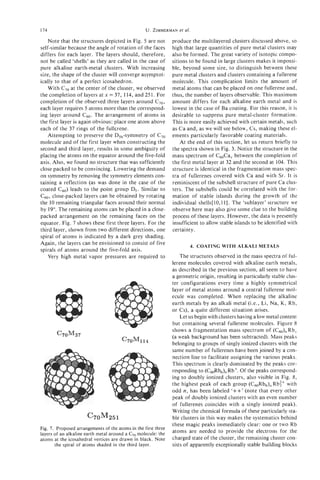
![Metal-coated fullerenes 175
300 3
2000
LixC,+,
1
Y
v)
FI
2
0
0 2000 4000 ' 6000 ' 8000
300
mass [amu]
Fig. 8. Mass spectrum, with background subtracted, of pho-
toionized (C,),Rb, clusters containing both singly and dou- Y
v)
bly ionized species: the solid line connects peaks belonging 0
to groups of singly ionized clusters with a fixed value of n. 1
Note the dominant peaks corresponding to (c,&b6),Rb+ 8
and (C60Rb6),Rb$+ (marked ' I + + " ) .
C6,Rb6. The corresponding building block can be 0
found in the mass spectra of clusters containing any 720 so0 900
alkali metal and Cm. Only Na is a minor exception to mass [amu]
the extent that the clusters (c60Na6),,Naf d o not show
Fig. 9. Mass spectra of singly (top) and doubly (bottom) ion-
up as especially strong peaks in the fragmentation ized C,Li, clusters: note the prominent features at x = 7 for
mass spectra. They do, however, mark a sharp fall- singly ionized and x = 8 for doubly ionized clusters and at
ing edge and a distinct change in the character of the x = 12 in both spectra.
spectra, as we will see later.
It seems quite obvious that the origin of the stabil-
ity of these building blocks is not geometric. More gly and doubly ionized CmLiw clusters. Mass peaks
likely, the electronic configuration of this unit is re- are, again, joined by a connecting line. The fine struc-
sponsible for the stability, the six valence electrons of ture of the peaks is caused by the two natural isotopes
the metal transferred to the six-fold degenerate t , , of Li. Again, we find prominent peaks at x = 7 for sin-
LUMO of the c 6 0 molecule. Such a transfer of six gly ionized and x = 8 for doubly ionized clusters. Ad-
electrons to the LUMO of Cm has also been observed ditionally, there are prominent peaks at x = 12 in both
in the bulk intercalation phases of C60M6 with M E (K, spectra. Twelve is exactly the number of electrons
Rb, Cs)[5]. These alkali metal fullerides become in- needed to fill the t , , and t , , orbitals, so it seems, at
sulators due to the complete filling of the t , , derived first, that we have found what we were looking for.
band (which was found to be only slightly disturbed However, remember that these clusters are charged,
by the presence of the alkali ions[5]). The appear- so the t l , orbital obviously cannot be filled com-
ance of such a building block is not limited to clusters pletely. Since the appearance of the magic number 12
containing c 0 Mass spectra of (C70)nMxshow ex-
6 . is independent of charge, it seems more promising to
actly the same intensity anomalies a t (C70M6)nM+ try a geometric interpretation. A b initio calculation
and (C70M6)nM:+. An explanation similar to the one shows that the twelve Li atoms have their equilibrium
given for c0 regarding the stability of the building
6 position above each of the twelve pentagonal faces
block observed holds for C,,[18]. and, thus, retain the icosahedral symmetry[l3]. It
Adhering to this interpretation, the bonding of the seems likely that this highly symmetrical arrangement
first six or seven alkali metal atoms will be primarily of atoms is responsible for the high stability of
ionic in nature. How will additional atoms attach t o C60LilL,independent of the state of charge, rather
the c0 molecule? Will they continue transferring
6 than a complete occupation of vacant molecular
their valence electrons to the next unoccupied orbital orbitals.
of C m ragain showing high stability when this six-fold To support this interpretation, we performed semi-
degenerate t l , orbital becomes filled? Looking for in- empirical quantum chemical calculations using the
formation supporting this hypothesis, we will begin modified-neglect-of-diatomic-overlap (MNDO) meth-
with an investigation of clusters having the composi- od[19,20]. For x = 1 . . . 14, we searched for the most
tion CbOLix. Based on ab initio calculations, it has stable ground state geometries of C,,Li,. We found
been suggested that the cluster C60Li12should be sta- that for x = 1 . . . 8 for Li atoms preferred to be cen-
ble with the valence electrons from the Li atoms fill- tered above the hexagonal faces of c60[12]. Exem-
ing both the t , , and the t , , orbitals[l3]. plarily, the geometry of C60Li8is shown in Fig. 10 on
Figure 9 shows fragmentation mass spectra of sin- the left. The eight Li atoms are situated at the corners](https://image.slidesharecdn.com/13709313-carbon-nanotubes-120928071547-phpapp01/85/13709313-carbon-nanotubes-188-320.jpg)
![176 U. ZIMMERMANal.
et
12
1 LiXC60". ' " '
' " " '
I
44 x = 7
12
n
j
Fig. 10. Most stable ground-state geometries found for
C d i , and C&i14 by the MNDO calculations: the Li atoms
are represented by the filled black circles.
of a cube. The bonds between the Li atoms (black)
I Li,C6," ? J
and the carbon atoms (white) were drawn merely to
clarify the geometry and are not meant to imply any
specific bonds. After a transition at x = 9, all Li at-
oms are found to be most stable when centered above
the pentagonal rings for x = 10. . . 12. For C6,,Li12,
the icosahedral arrangement of Li atoms proved to be
significantly lower in energy than all other isomers, in- 0 2 4 6 8 1 0 1 2 1 4
dependent of the charge of the cluster, while for clus-
ters with x around 7, the number of electrons in the
# of Li-atoms on c,,
cluster dominated over the geometry in determining Fig. 11. Abundance mass spectra of differently charged hot
the total binding energy of the cluster. Interpreting the C,,Li, clusters evaporating atoms calculated with a Monte-
magic numbers x = 7 and x = 8 to be of electronic and Carlo simulation (the Li and C,, isotope distributions are
x = 12 to be of geometric origin thus seems reasonable. included). Energies required to remove Li atoms were calcu-
For CsoLi13,the most stable geometry has 12 Li lated using the MNDO method. The peaks at x = 12 and at
+
x = 6 n (where n is the cluster charge) observed in experi-
atoms above the pentagons and one above a hexagon. ment (Fig. 9) are well reproduced.
If a fourteenth atom is placed near the Li atom above
a hexagon, the arrangement of Li atoms becomes un-
stable. The two Li atoms initially not above a penta-
gon of c ( will then slide on top of a pentagon. The
6, on the surface of Cs0 (remember that the MNDO cal-
resulting most stable geometry of C60Li,4 has one culations already show the formation of a metal tri-
equilateral Li trimer (Li-Li bond length of 2.23 A) mer for x = 14). The electronic configuration of the
lying flat above a pentagon and 11 Li atoms centered clusters would, then, again determine their relative sta-
above the remaining pentagons of C as shown in
,
o bility just as it does for pure alkali metal clusters. Con-
Fig. 10 on the right. For comparison: MNDO calcu- sistent with this 'electronic'interpretation, the even-odd
lates a bond length of 2.45 A for the isolated Li: alternation displayed by the doubly ionized clusters is
(equilateral triangle) and 2.19 A for the two short shifted by one atom with respect to the singly ionized
bonds of neutral Li3. clusters, an additional Li ion required to supply the
From the binding energies calculated for the dif- charge of the cluster.
ferent cluster compositions, we determined abundance Such an even-odd alternation is observed to a dif-
mass spectra for heated C6,LiXclusters from a simple ferent degree for all alkali metals covering fullerene
Monte Carlo simulation. Figure 11 shows the simu- molecules (see also Fig. 8). It is especially strong for
lated mass spectra resulting from these calculations, Na. Fig. 12 shows a fragmentation mass spectrum of
including the Li and C, isotope distributions. The singly charged C&ax. A strong even-odd alternation
+
peaks at x = 12 and at x = 6 n (where n is the clus- starts above x = 7, the point at which we suggested the
ter charge) observed in the experiment (Fig. 9) are well metal-metal bonding to begin, and extends up to ap-
reproduced. For more details, see ref. [12]. proximately x = 66. Note that x = 12 does not appear
For values of x greater than 14, a strong even-odd as a magic number in these spectra. In fact, Li is the
alternation becomes visible in the spectra shown in only metal for which this magic number is observed.
Fig. 9, peaks corresponding to clusters with an even One possible explanation as to why Li behaves differ-
number of available metal valence electrons being ently is the ability of Li atoms to form covalent bonds
stronger. We suggest that this even-odd alternation, with carbon because the Li 2s orbital is close enough
similarly observed in pure alkali metal clusters, signals in energy to the carbon valence orbitals. Other than
the onset of metal-metal bonding of the metal atoms Li, the higher alkali metals form essentially ion pairs](https://image.slidesharecdn.com/13709313-carbon-nanotubes-120928071547-phpapp01/85/13709313-carbon-nanotubes-189-320.jpg)
![0 20 40 60
No. of Na-atoms on CG0
Fig. 12. Mass spectra of singly charged clusters composed of a single C molecule coated with a large
,
amount of Na (background subtracted). The even-odd alternation extends up to approximately x = 66.
Note that x = 12 does not appear as a magic number in these spectra.
in the gas phase (a Li' ion is exceptionally small and ing additional metal atoms around them as the clus-
has, therefore, an exceptionally high charge-radius ra- ter increases its metal content. This would result in at
tio, comparable to that of Mg2+). A neighboring neg- least one metallic layer coating the molecule (so speak-
atively charged fuIlerene would be polarized to such ing of metal-coated fullerenes seems justified). How-
an extent that the description as ion pair would not be ever, we do not have any evidence from the spectra
justified. The configuration of Li atoms around Cb0 indicating when this layer will be completed (a rough
might, therefore, be influenced more strongly by the estimate shows that a first metal layer, for example of
structure of the fullerene molecule than is the case for Cs, would require around 30 atoms for completion).
other alkali metals, resulting in the unique configura- As we have already mentioned, the stability of the
tion and stability of C6,,Li12. alkali-fullerene clusters seems to be primarily deter-
TJnfortunately, in the case of fullerenes covered mined by the electronic configuration. Therefore, it
with alkali metals, clear evidence is lacking regarding is not too surprising that completion of a Payer of at-
the geometry of the clusters. We can, therefore, only oms, which would be a geometrically favorable struc-
present speculation that may appear plausible but can- ture, does not lead to any pronounced features in the
not be proven presently. The first seven Na ions of the mass spectra. Furthermore, it should be emphasized
C,Na: clusters arrange themselves as far from each that to obtain these fragmentation spectra, the clus-
other as possible to minimize coulomb repulsion while ters have been heated up to a temperature at which
adhering to the C, molecule. Additional Na atoms they evaporate atoms on a psec time scale. This cor-
might successively attach to these 7 ions in pairs of responds to a temperature at which bulk alkali metals
two, forming Na: trimers similar to the one calcu- are molten. Incidentally, a similar behavior is observed
lated for Cs0Lil4. Every time such a stable trimer, in pure metal clusters: small alkali clusters (less than
each containing two metal valence electrons, is com- 1500 atoms) show electronic shells and alkaline earth
pleted, a strong peak is observed in the spectrum, re- clusters show geometric shells[9,10].
sulting in an even-odd alternation. The abrupt change When the cluster, containing one fullerene, contin-
in the strength of this alternation at x = 21 = 3 X 7 ues to grow by adding more metal, it will probably as-
Na atoms fits this speculation. sume the more or less spherical shape observed for
When coating fuIlerenes with larger alkali metal at- pure alkali metal clusters. It could, then, be viewed as
oms, the even-odd alternation is interrupted before a metal cluster with a large 'impurity': the fullerene.
reaching x = 21, so the structural sequence must be Alkali metal clusters containing small impurities, such
different for these. Nevertheless, we do suggest that as (SO,), or O n , have already been studied[21,22],
the first 6 alkali metal atoms, having transferred their showing that the main influence of the impurity is to
valence electron to the fullerene molecule, will remain shift the number of atoms at which electronic shell
distributed over the surface of the fullerene, gather- closings are observed upwards by 2n, 2 being the num-](https://image.slidesharecdn.com/13709313-carbon-nanotubes-120928071547-phpapp01/85/13709313-carbon-nanotubes-190-320.jpg)
![178 et
U. ZIMMERMAN at.
ber of electrons bonded by SO2 and 0. What effect there is some correlation between the two sets of num-
does C60 as an impurity have on the electronic shell bers, but no exact agreement. If we make the simpli-
structure? Will it merely shift the shell closings by 6 fying assumption that six Cs atoms transfer their
(the number of electrons possibly transferred to the valence electrons to the c0 molecule and that these
6
c 6 0 molecule)? We will investigate this in the follow- electrons will no longer contribute to tne sea of quasi-
ing paragraphs. free electrons within the metal portion of the cluster,
Up to this point, we have always studied the clus- the number 6 should be subtracted from the shell clos-
ters using brute force (i.e., heating them so strongly ings observed for metal-coated c 6 0 . This improves
that they evaporate atoms). But the electronic shell the agreement between the two sets of shells. How-
structure of clusters can also be investigated more gen- ever, it is really not surprising that the agreement is
tly by keeping the photon flux low enough to prevent still not perfect, because a c 6 0 molecule present in a
the clusters from being heated and using photon en- metal cluster will not only bond a fixed number of
ergies in the vicinity of the ionization energy of the electrons but will also act as a barrier for the remain-
clusters. ing quasi-free metal electrons. Using the bulk density
The ionization energy of alkali metal clusters os- of Cs, a spherical cluster Cs,,, has a radius of ap-
cillates with increasing cluster size. These oscillations proximately 24 A. A Cm molecule with a radius of
are caused by the fact that the s-electrons move almost approximately 4 A should, therefore, constitute a bar-
freely inside the cluster and are organized into so- rier of noticeable size. To get some idea of the effect
called shells. In this respect, the clusters behave like such a barrier has on the shell closings, let us consider
giant atoms. If the cluster contains just the right num- the following simple model.
ber of electrons to fill a shell, the cluster behaves like The metal cluster will be modeled as an infinitely
an inert gas atom (Le., it has a high ionization energy). deep spherical potential well with the C60represented
Howeve?, by adding just one more atom (and, there- by an infinitely high spherical barrier. Let us place this
fore, an additional s-electron), a new electronic shell barrier in the center of the spherical cluster to simplify
must be opened, causing a sharp drop in the ioniza- the calculations. The simple Schrodinger equation,
tion energy. It is a tedious task to measure the ioniza- containing only the interaction of the electrons with
tion energy of each of hundreds of differently sized the static potential and the kinetic energy term and ne-
clusters. Fortunately, shell oscillations in the ioniza- glecting any electron-electron interaction, can then be
tion energy can be observed in a much simpler exper- solved analytically, the solutions for the radial wave
iment. By choosing the wavelength of the ionizing light functions being linear combinations of spherical Bessel
so that the photon energy is not sufficient to ionize and Neumann functions.
closed-shell clusters, but is high enough to ionize open- Such a simple model, without the barrier due to the
shell clusters, shell oscillations can be observed in a c 6 0 at the center, has been used to calculate the elec-
single mass spectrum. Just as in the periodic table of tronic shell structure of pure alkali metal clusters[9].
elements, the sharpest change in the ionization energy
occurs between a completely filled shell and a shell
containing just one electron. In a threshold-ionization
mass spectrum this will be reflected as a mass peak of Table 1. Comparison of experimentally observed electronic
zero intensity (closed shell) followed by a mass peak shell closings with model calculations*
-
at high intensity (one electron in a new shell). This be-
Experiment Potential well
havior is often seen. However, it is not unusual to find
that this step in the mass spectrum is ‘washed out’ for c @
6 , M, [21,23] With barrier Without barrier
large clusters due to the fact that the ionization thresh-
old of a single cluster is not perfectly sharp. 12 f 0 8 8 8
Figure 13 shows a set of spectra of C60Cs, clusters 27 f 1 20 20 20
33 f 1 34 32 34
for three different wavelengths of the ionizing laser. 44 f 0 40 40
Note the strong oscillations in the spectra. Plotted on 61 f 1 58 50 58
a n1’3 scale, these oscillations occur with an equal 80
spacing. This is a first hint that we are dealing with *
98 1 92 90 92
146 f 2 138 130 138
a shell structure. Because this spacing is almost iden- 178 186
tical to the one observed in pure alkali metal clusters, 198 i 0 198 i 2 196
these oscillations are most certainly due to electronic 255 f 5 263 f 5 252 254
rather than geometric shells. The number of atoms at 352 f 10 341 f 5 330 338
which the shell closings occur are labeled in Fig. 13 445 f 10 443 a 5 428 440
and listed in Table 1. Note that these values do not *See text. The first two columns give the numbers of
correspond to the minima in the spectra as long as metal atoms at which electronic shell closings have been ob-
these have not reached zero signal. served in experiment for Cscovered C,, and for pure alkali
Also listed in Table 1 are the shell closings observed metal clusters, respectively. The columns on the right list the
number of electrons required for shell closings in an infinitely
in pure alkali metal clusters[9,21,23]. These values and deep potential well with and without a central barrier. The
the ones observed for the Cs-covered Cm have been numbers in the different columns are mainly arranged in a
arranged in the table in such a way as to show that manner to show correlations.](https://image.slidesharecdn.com/13709313-carbon-nanotubes-120928071547-phpapp01/85/13709313-carbon-nanotubes-191-320.jpg)
![180 U. ZIMMERMAN ai.
et
preted to signal the onset of metal-metal bonding. An
exception to the electronically determined cluster sta-
bility is C60Li12,which was observed to be particularly
stable independent of the cluster charge. Supported by
MNDO calculations, we found that the geometrical ar-
rangement of atoms in this cluster, one above each
pentagon of the fullerene, was most important for the
stability. At higher alkali metal coverage of the ful-
lerene, an electronic shell structure similar to pure
metal clusters is observed in the ionization threshold
of the clusters.
Acknowledgements-We would like to thank H. Schaber for
his outstanding technical assistance, U. Naher for many stim-
ulating discussions, and A. Mittelbach for providing the C,,
used in the experiments.
I
S
’ I , ,, , , , , , , , , REFERENCES
0.0 0.2 0.4 06
. 0.8
RCJR0.t 1. A. E Hebard, M. J. Rosseinsky, R. C. Haddon, D W.
Murphy, S. H. Glarum, T. T. Palstra, A. P. Ramirez,
Fig. 14. Energy levels calculated for an infinitely deep spher- and A. R. Kortan, Nature 350, 600 (1991).
ical potential well of radius R , with an infinitely high cen-
,, 2 . K. Holczer, 0. Klein, S.-M. Huang, R. E. Kaner, K . 4 .
tral potential barrier with a radius Rc6,; the zigzag line Fu, R. L. Whetten, and E Diederich, Science 252, 1154
corresponds to the path of the highest occupied level of a (1991).
C,Cs, cluster as it grows from x = 1 to x = 500. 3. P W. Stephens, L. Mihaly, J. B. Wiley, S.-M. Huang,
.
R. B. Kaner, E Diederich, R. L. Whetten, and K. Holc-
zer, Phys. Rev. B 45, 543 (1992).
4. A. R. Kortan, N. Kopylov, S. Glarum, E. M. Gyogy,
change significantly when placing a ‘hole’ in its cen- A. P. Ramirez, R. M. Fleming, 0. Zhou, E A. Thiel,
ter. This qualitative result is in agreement with the P. L. Trevor, and R. C. Haddon, Nature 360,566 (1992).
5 . D. W. Murphy, M. Z. Rosseinsky, R. M. Fleming, eta/.,
experimental observation. Similar results can be ob- J. Phys. Chem. Solids 53, 1321 (1992).
tained from self-consistent jellium calculations[%]. 6. P. Weis, R. D. Beck, G. Brauchle, and M. M. Kappes,
J. Chem. Phys. 100, 5684 (1994).
7. U. Zimmermann, N. Malinowski, U. Naher, S. Frank,
5. SUMMARY and T. P. Martin, Phys. Rev. Lett. 72, 3542 (1994).
8. T. P. Martin, N. Malinowski, U. Zimmermann, U. Na-
By coevaporation of fullerenes and metal in a gas her, and H. Schaber, J. Chem. Phw. 99. 4210 (1993).
aggregation cell, metal-fullerene clusters having a va- 9. T. P. Martin, T. Bergmann, H. Gohlich, and T. Lange,
riety of compositions can be produced. Investigating J. Phys. Chem. 95, 6421 (1991).
such clusters using time-of-flight mass spectrometry, 10. T. P. Martin, U. Naher, T. Bergmann, H. Gohlich, and
T. Lange, Chem. Phys. Lett. 183, 119 (1991).
we found that alkaline earth metals will coat single ful- 1 1 . T. P. Martin, T. Bergmann, H. Gohlich, and T. Lange,
lerene molecules with up to four distinct layers of Chem. Phys. Lett. 176, 343 (1991).
metal atoms. Clusters with complete metal layers 12. U. Zimmermann, A. Burkhardt, N. Malinowski, U. Na-
proved to be particularly stable and appeared with en- her, and T. P. Martin, J. Chem. Phys. 101, 2244 (1994).
hanced intensity in the mass spectra. The number of 13. J. Kohanoff, W. Andreoni, and M. Parinello, Chem.
Phys. Lett. 198, 472 (1992).
atoms required to complete such a layer is identical for 14. L. Pauling, J. Am. Chem. SOC. 69, 542 (1947).
each alkaline earth metal. A geometrical arrangement 15. C. S. Yannoni, P. P. Bernier, D. S. Bethune, G. Meijer,
of atoms, having I-symmetry in the case of coated and J. K. Salem, J. A m . Chem. Soc. 113, 3190 (1991).
c0 and D,-symmetry in the case of coated C,,,was
6 16. A. L. Mackay, Acta Crystallogr. 15, 916 (1962).
17. U. Naher, U. Zimmermann, and T. P. Martin, J. Chem.
proposed for each layer. The number of alkaline earth Phys. 99, 2256 (1993).
atoms in the first layer of metal on c 6 0 or C70is iden- 18. J. H. Weaver, J. Phys. Chem. Solids 53, 1433 (1992).
tical to the number of carbon rings on the surface of 19. M. J. S. Dewar and W. Thiel, J. Am. Chem. SOC.99,
the fullerene coated, so it seems possible to ‘count’ 4899 (1977).
these rings. 20. M. J. S. Dewar and W. Thiel, J. Am. Ckem. SOC.99,
4907 (1977).
In coating fullerenes with alkali metals, the stabil- 21. H. Gohlich, T. Lange, T. Bergmann, and T. P. Martin,
ity of the cluster seemed to be determined primarily Phys. Rev. Lett. 65, 748 (1990).
by the electronic configuration. The units C&i6 and 22. H. Gohlich, T. Lange, T. Bergmann, and T. P. Martin,
C7oM6, where M is any alkali metal, proved to be ex- Z . Phys D 19, 117 (1991).
23. W. D. Knight, K. Clemenger, W. A. de Heer, W. A.
ceptionally stable cluster building blocks. Coating a Saunders, M. Y. Chou, and M. L. Cohen, Phys. Rev.
fullerene with more than 7 alkali metal atoms led to Lett. 52, 2141 (1984).
an even-odd alternation in the mass spectra, inter- 24. S. Satpathy and M. Springborg, private communications.](https://image.slidesharecdn.com/13709313-carbon-nanotubes-120928071547-phpapp01/85/13709313-carbon-nanotubes-193-320.jpg)
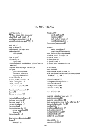


![Shalegas gwpf[1]](https://cdn.slidesharecdn.com/ss_thumbnails/shalegasgwpf1-120305101317-phpapp02-thumbnail.jpg?width=640&height=640&fit=bounds)


