Download to read offline
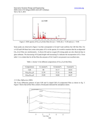
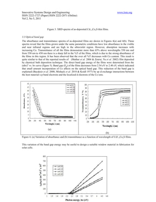
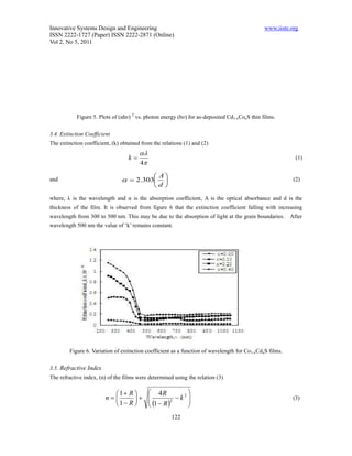
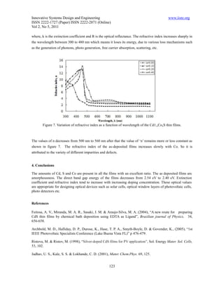

This document summarizes research on cadmium sulfide (CdS) thin films doped with cobalt (Co) prepared using the spray pyrolysis technique. Key findings include: 1. Cd1-xCoxS thin films were deposited on glass substrates at 523K for x=0.00, 0.10, 0.20, and 0.40 compositions. 2. Energy dispersive X-ray analysis confirmed the presence of Cd, S, and Co in the appropriate stoichiometric ratios. 3. X-ray diffraction showed all films were amorphous in nature as deposited. 4. The optical band gap decreased from 2.54 eV to 2.40 eV


