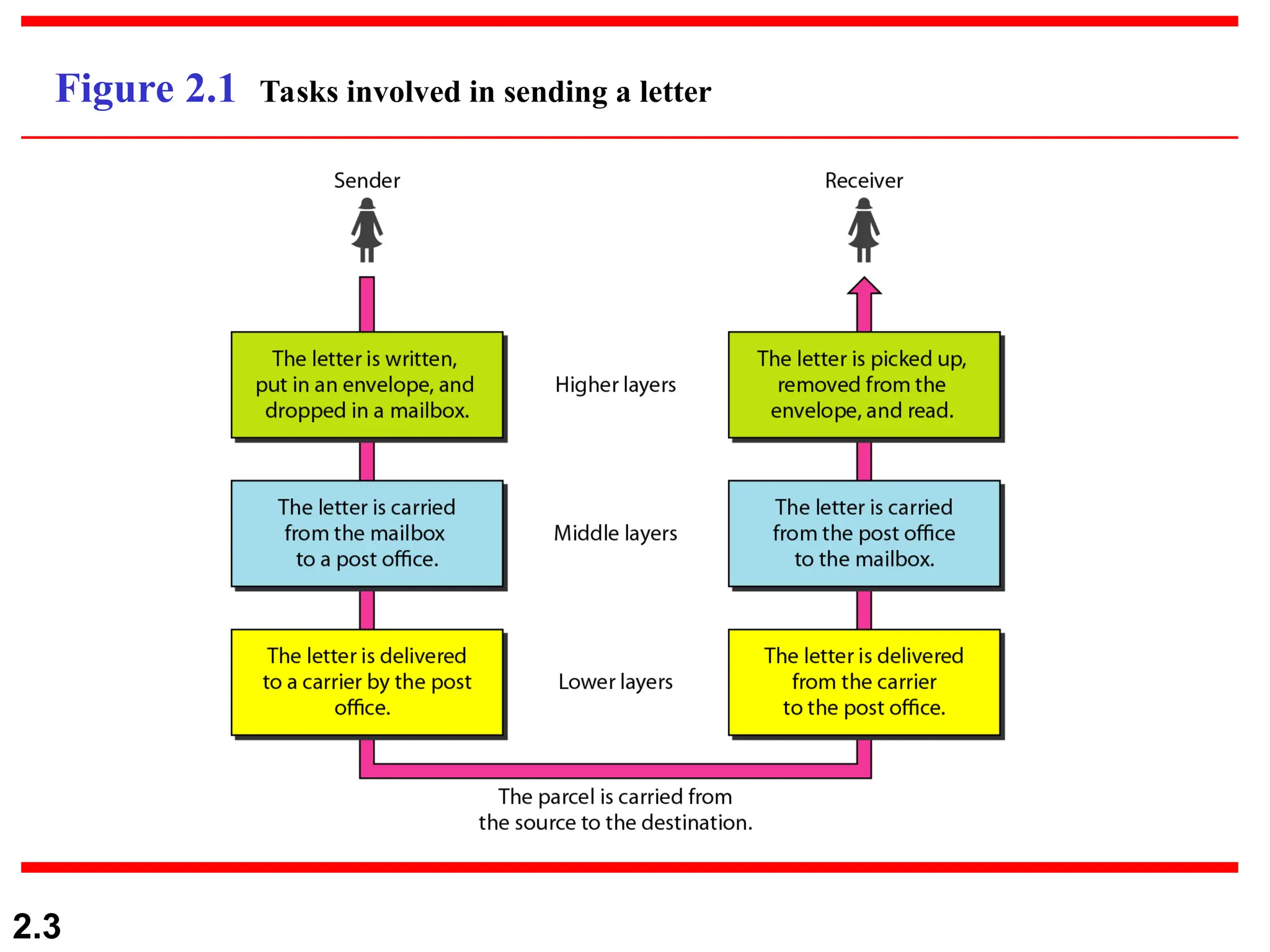
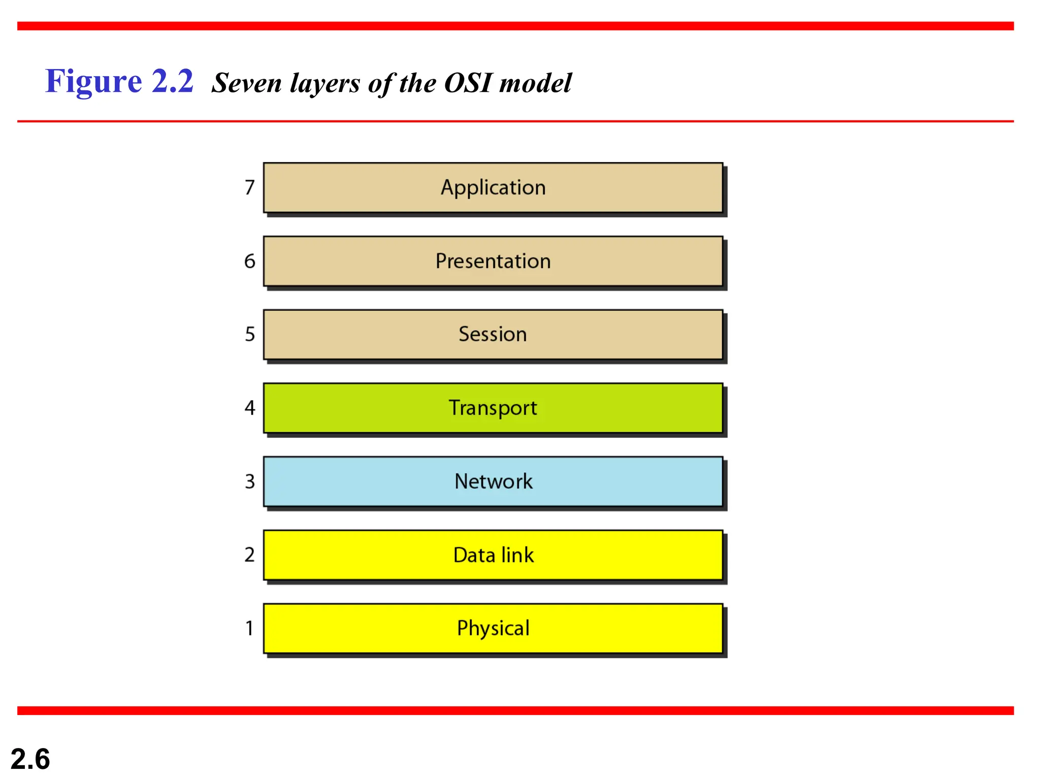
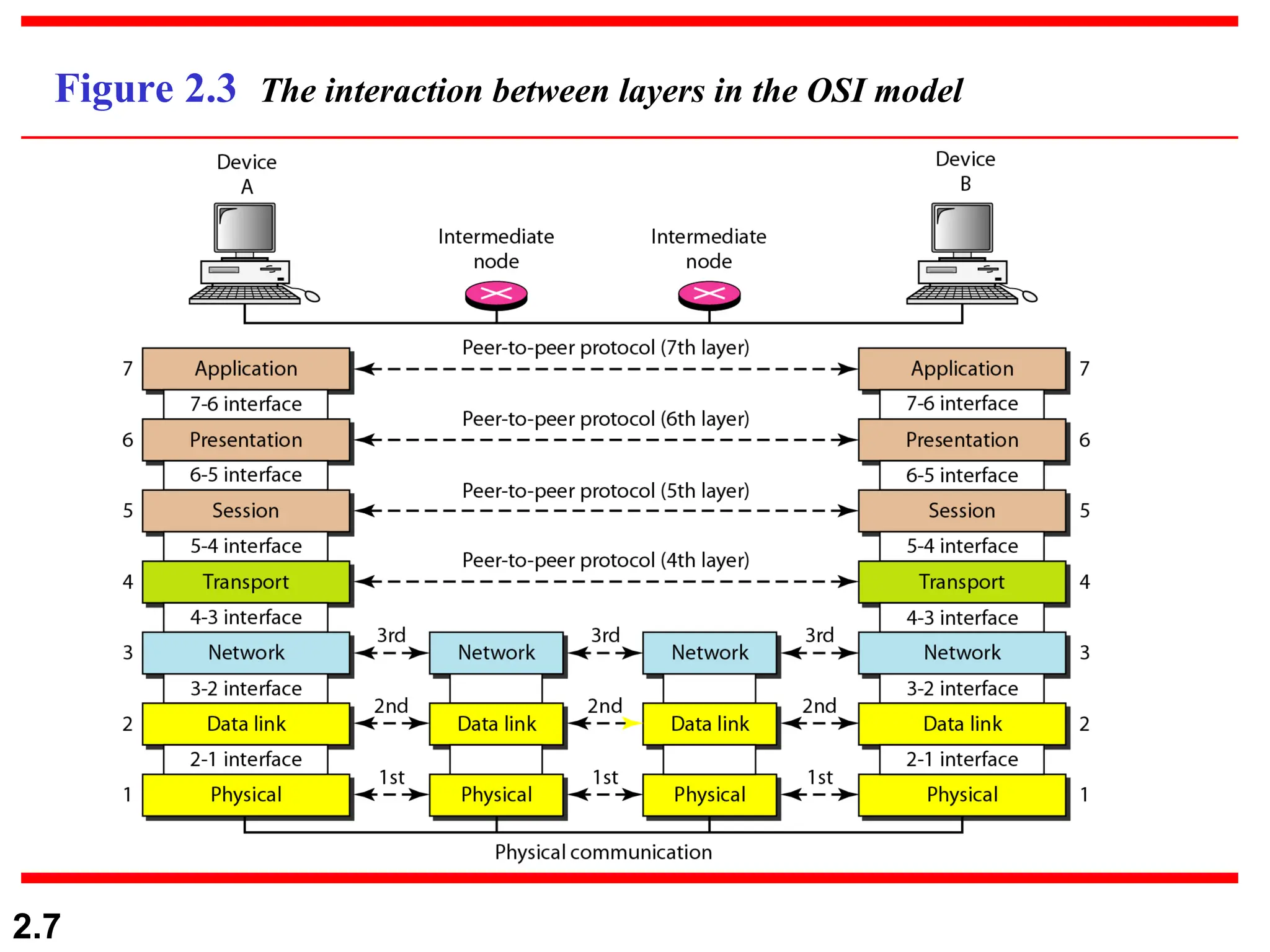
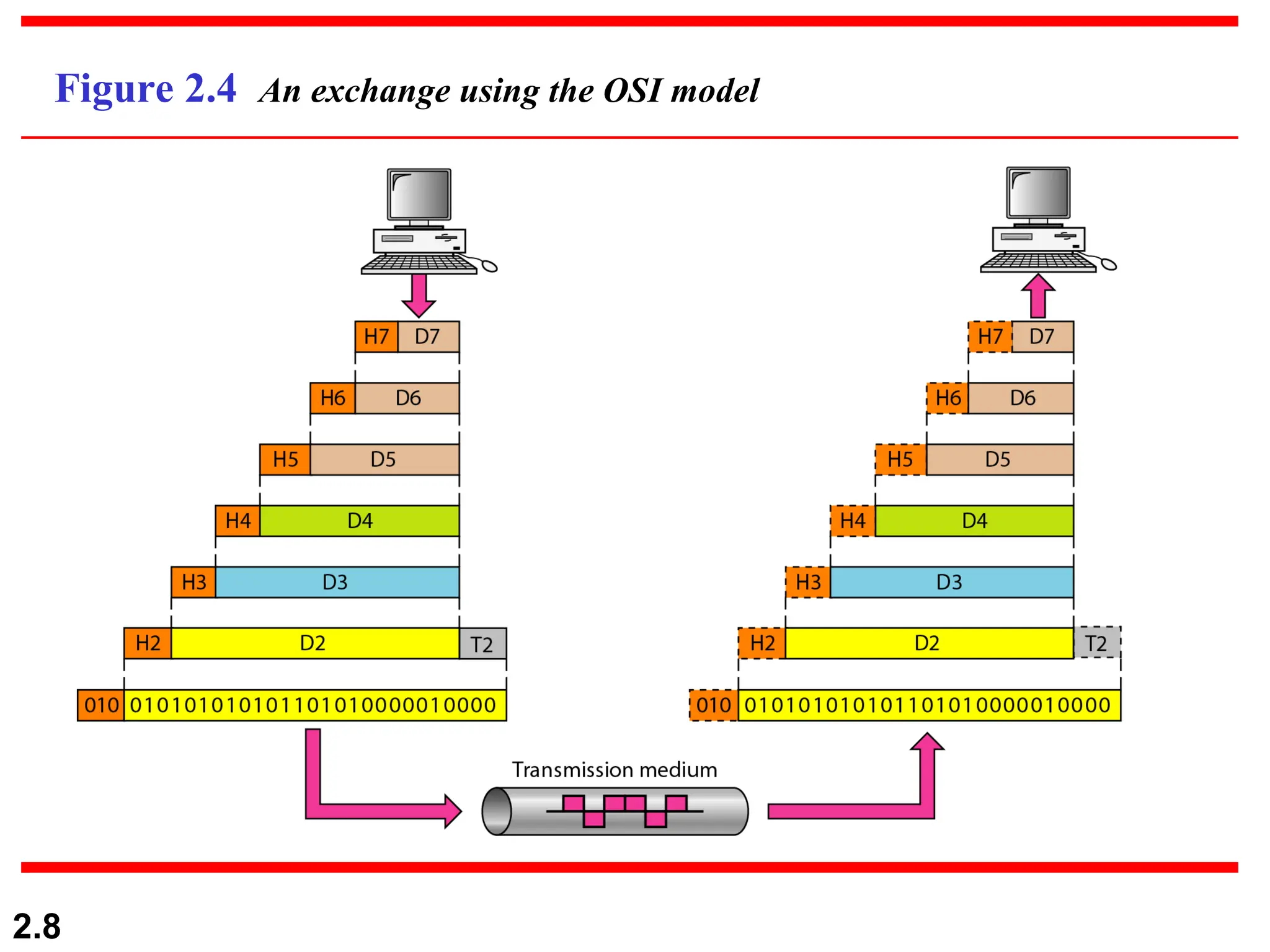
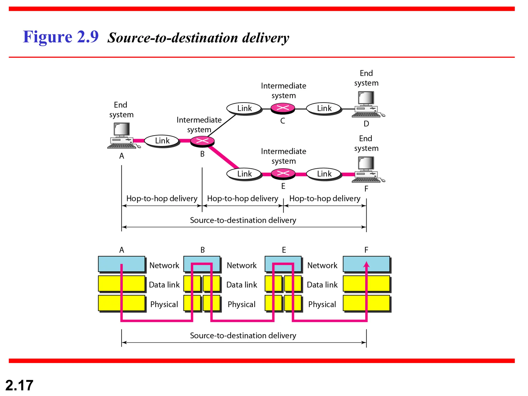
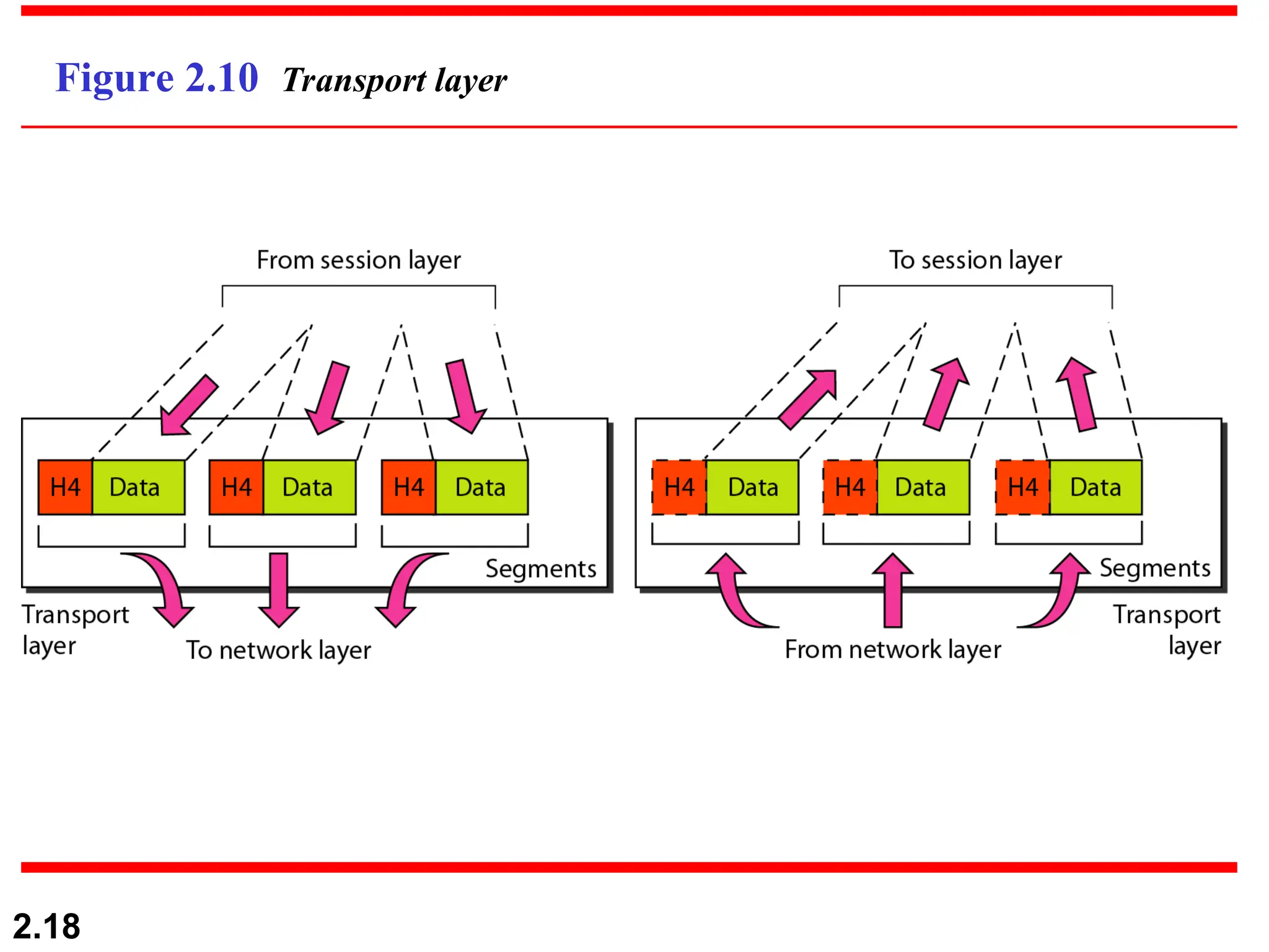
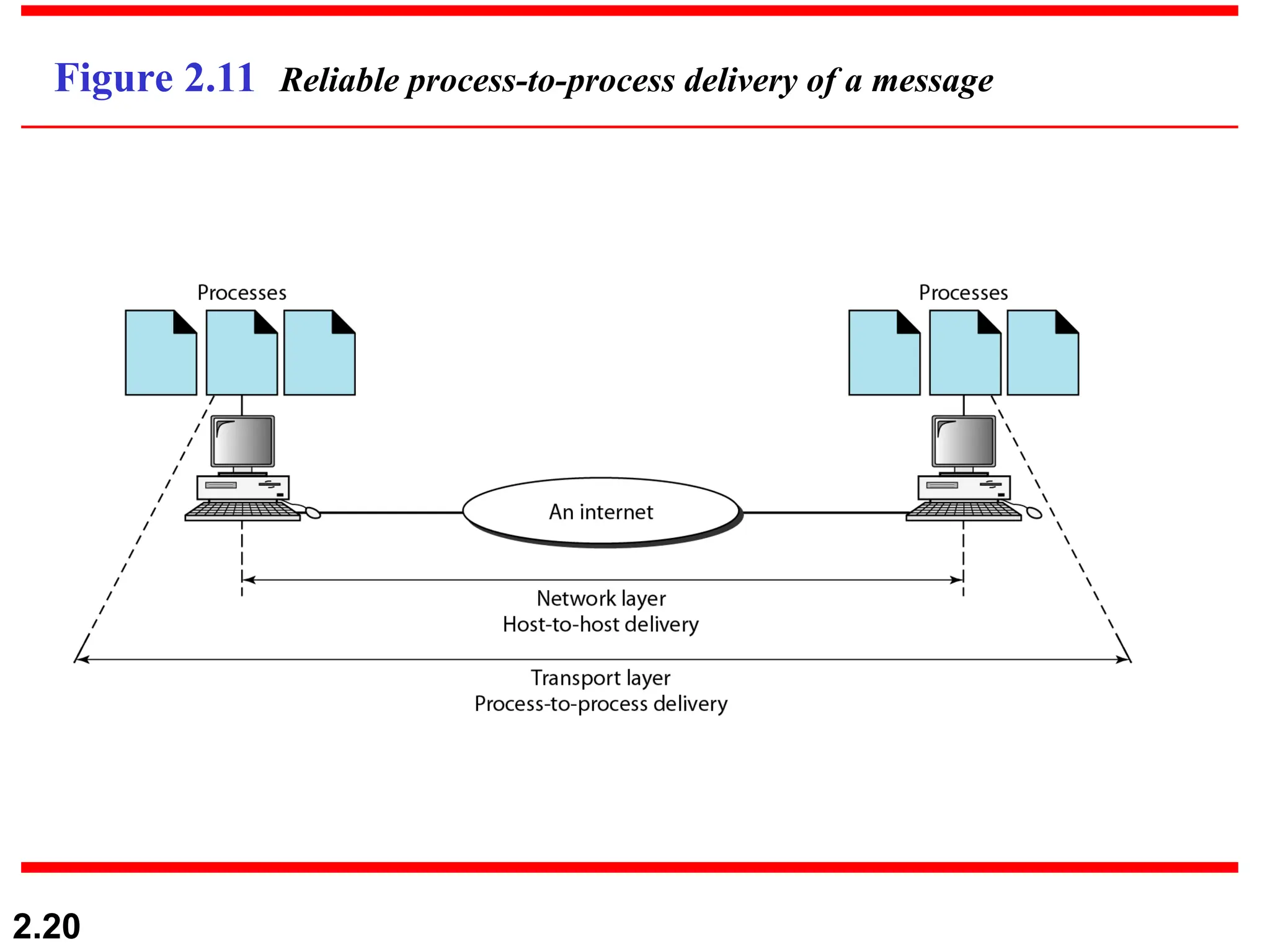
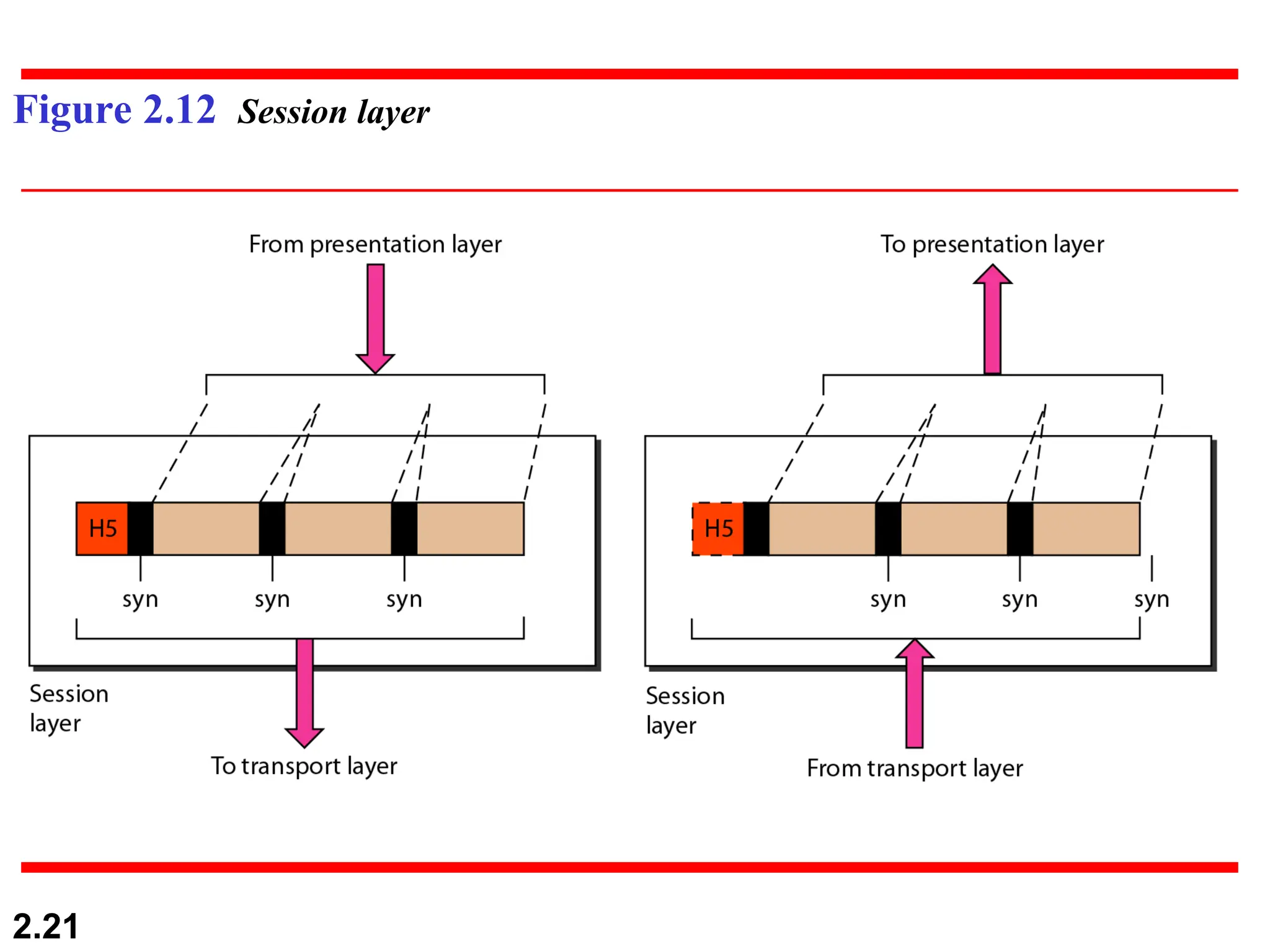
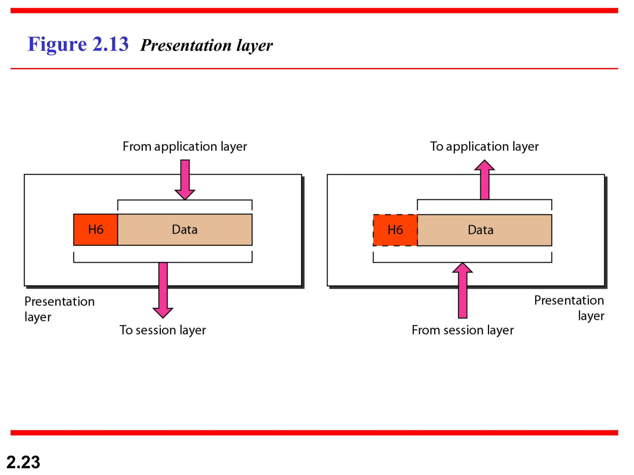
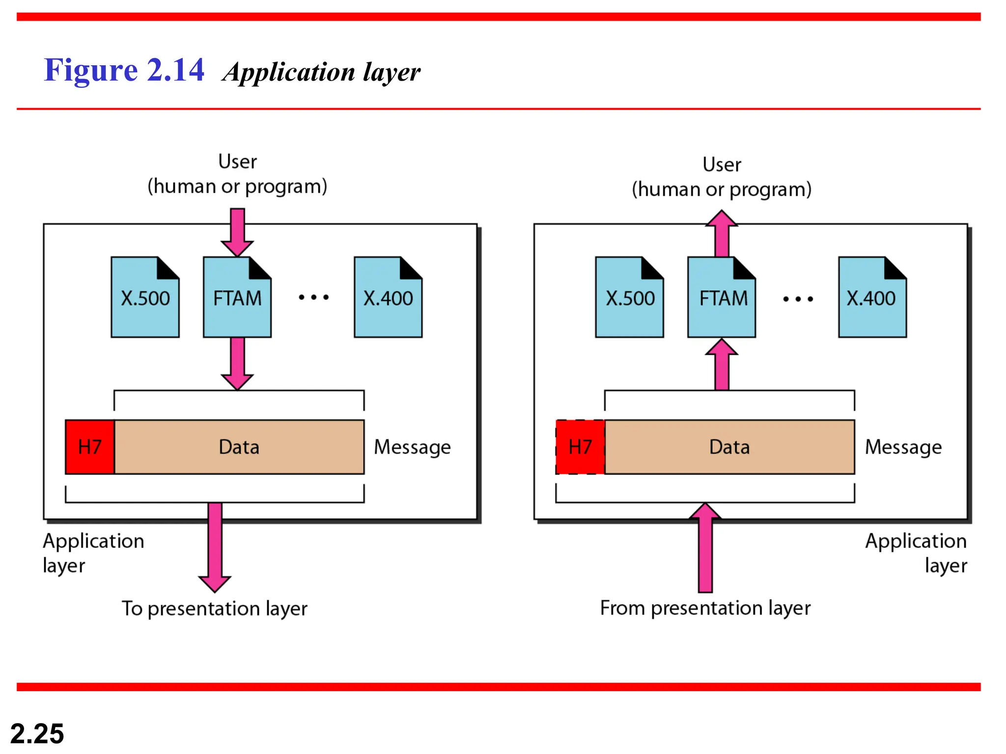
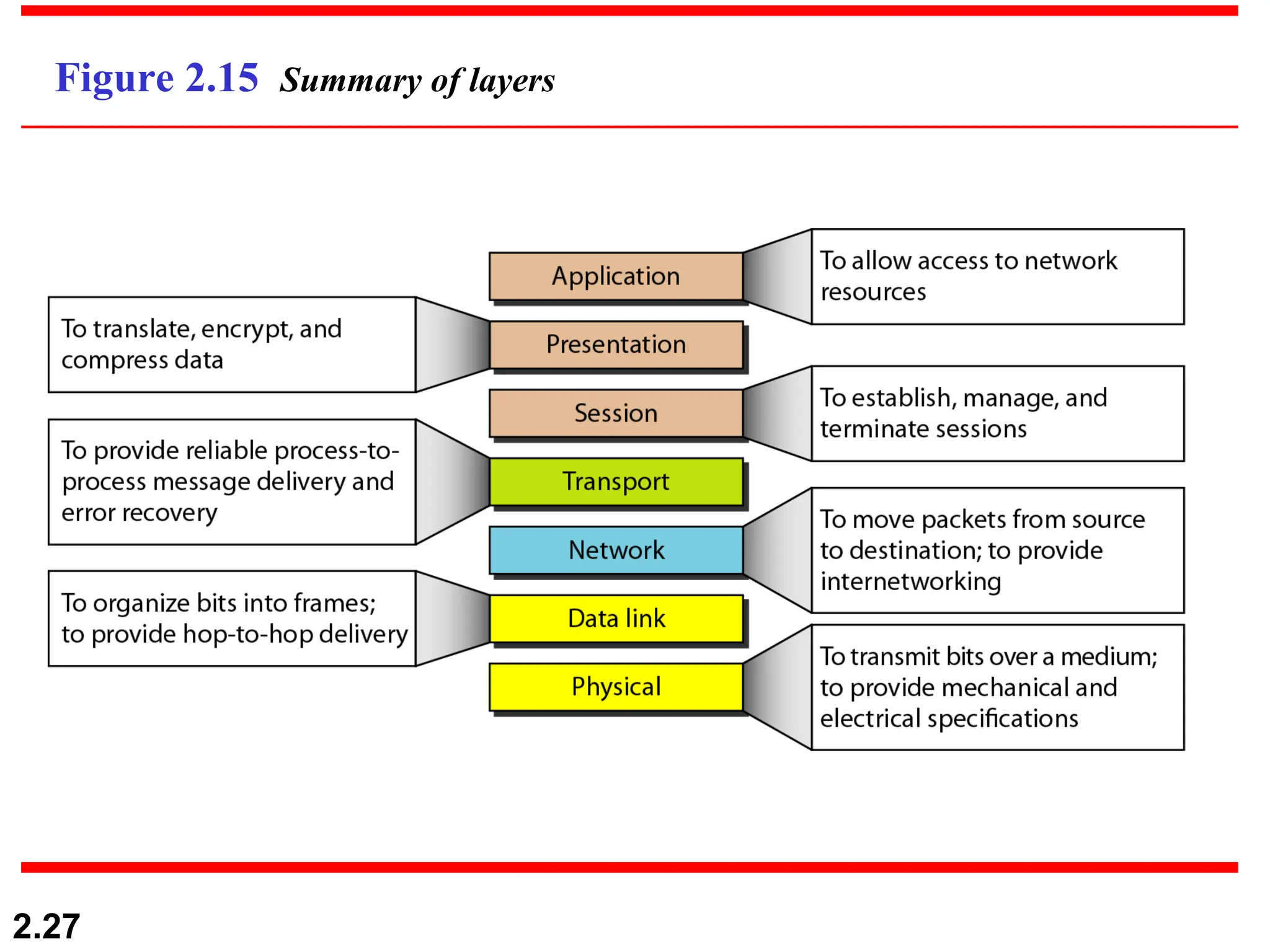
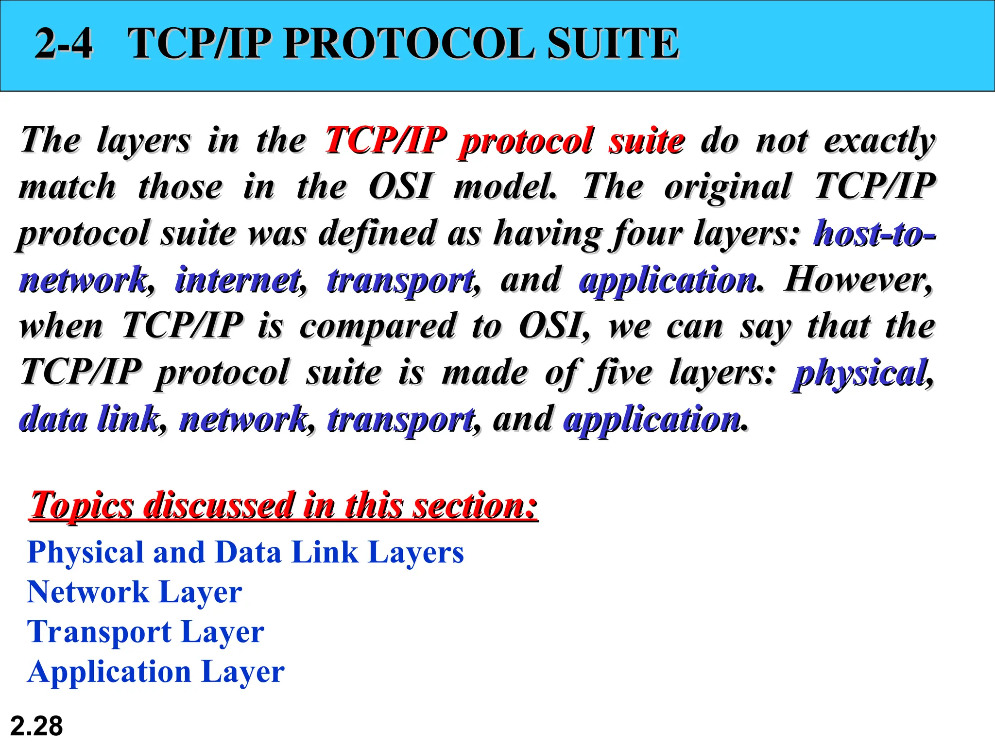
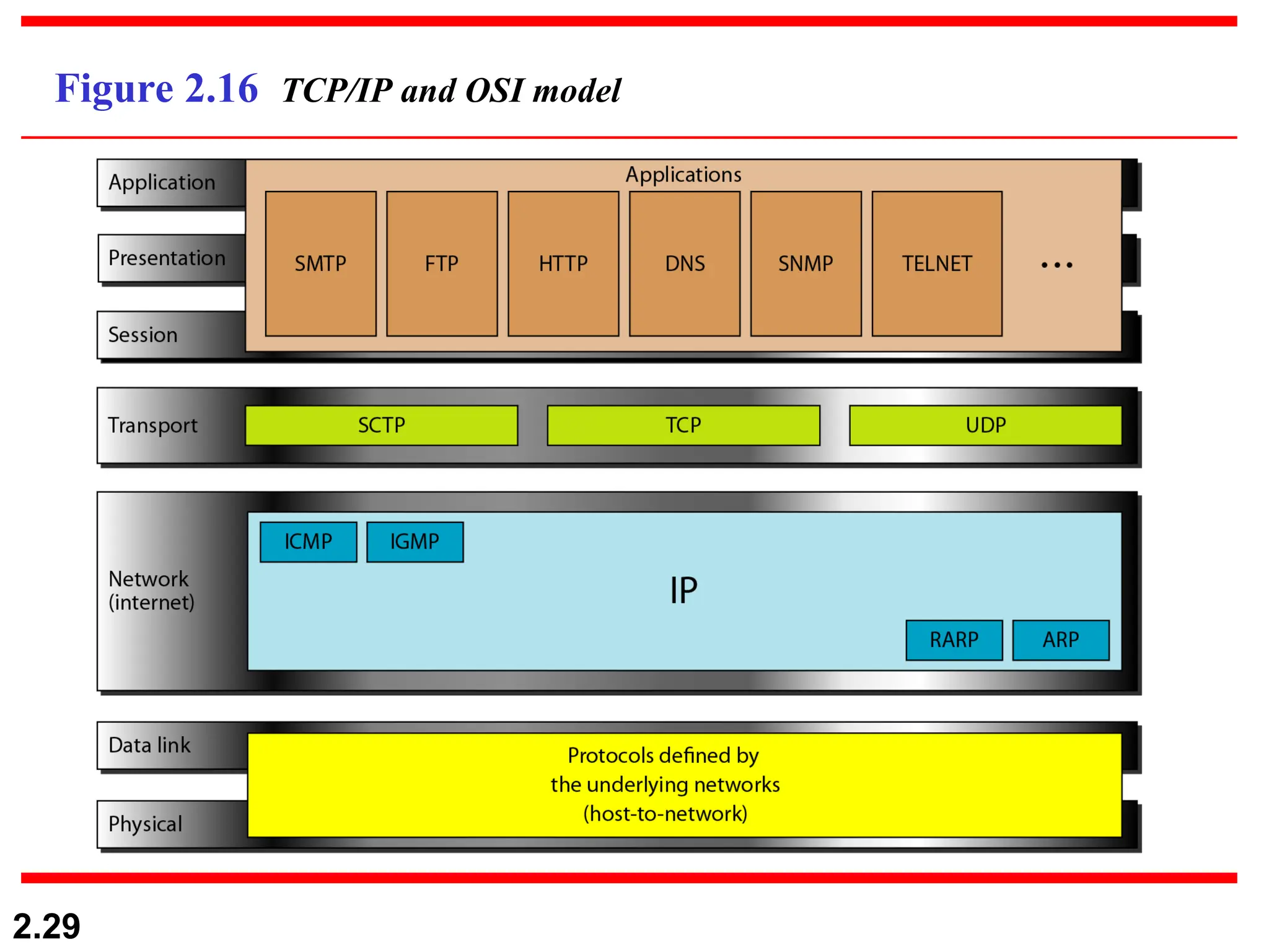
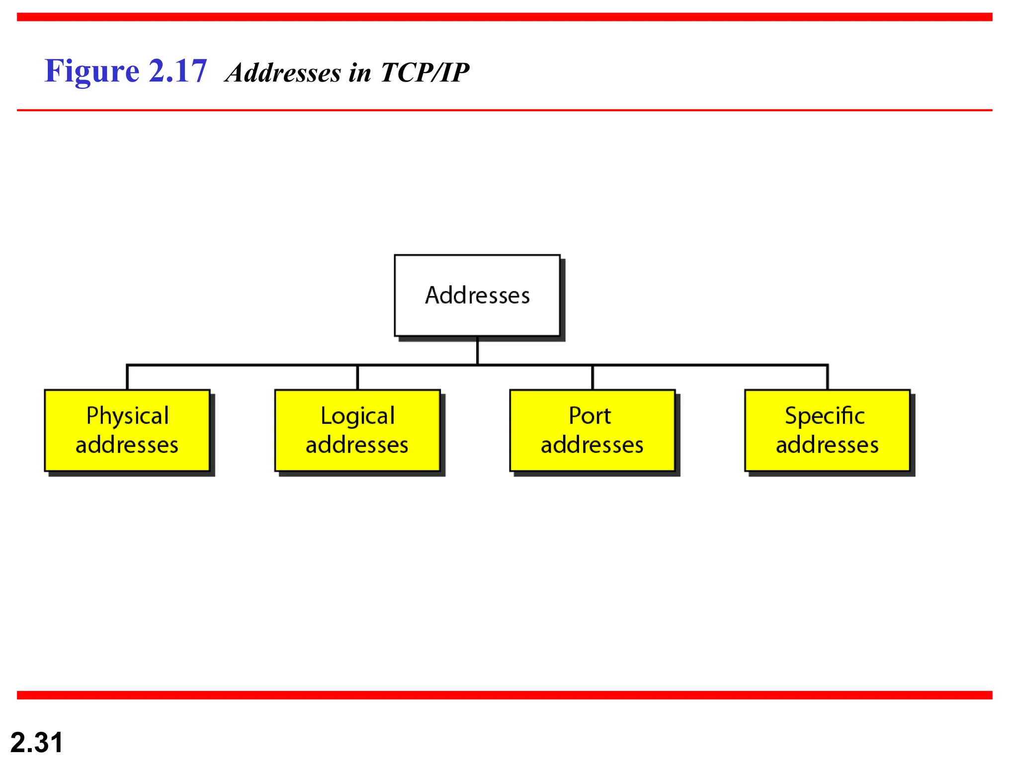
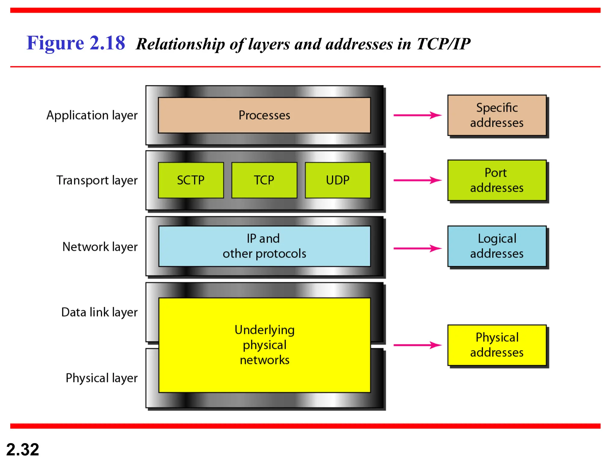
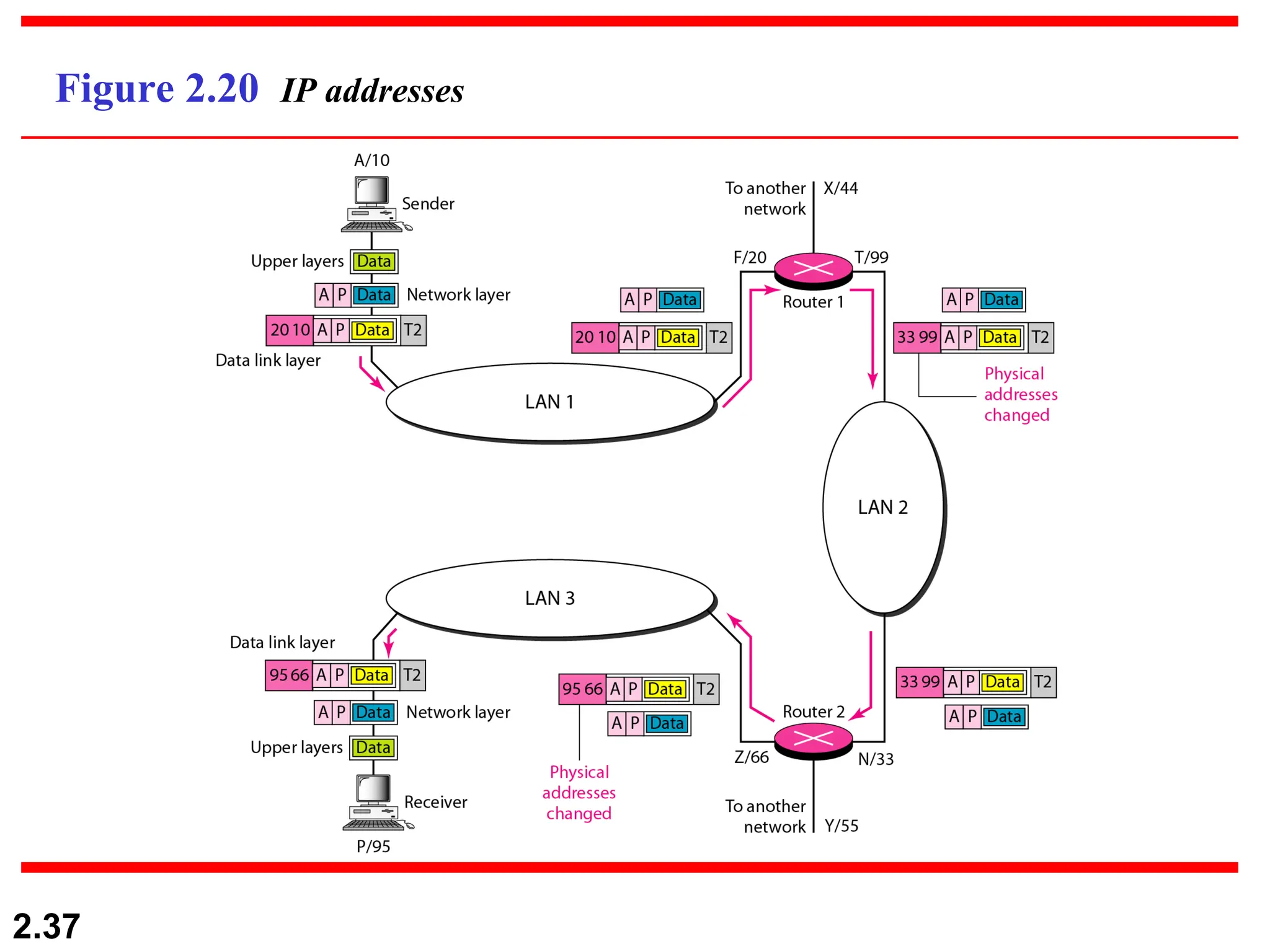
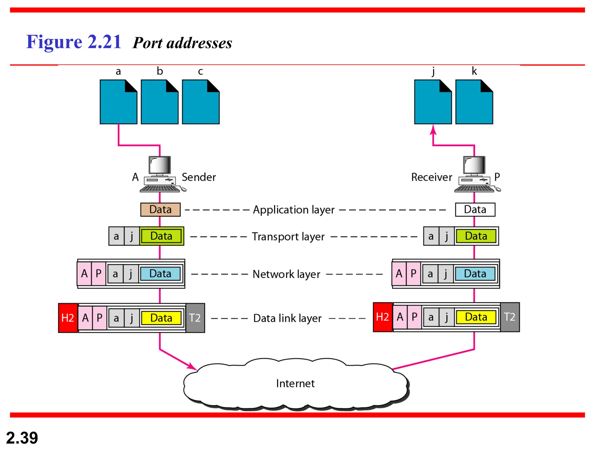
2.1
Chapter 2
Network Models
Copyright © The McGraw-Hill Companies, Inc. Permission required for reproduction or display.
2.2
2-1 LAYERED TASKS
2-1 LAYERED TASKS
We use the concept of
We use the concept of layers
layers in our daily life. As an
in our daily life. As an
example, let us consider two friends who communicate
through postal mail. The process of sending a letter to a
friend would be complex if there were no services
available from the post office.
Sender, Receiver, and Carrier
Hierarchy
Topics discussed in this section:
2.3
Figure 2.1 Tasks involved in sending a letter
2.4
2-2 THE OSI MODEL
2-2 THE OSI MODEL
Established in 1947, the International Standards
Organization (
Organization (ISO
ISO) is a multinational body dedicated to
) is a multinational body dedicated to
worldwide agreement on international standards. An ISO
standard that covers all aspects of network
communications is the Open Systems Interconnection
(
(OSI
OSI) model. It was first introduced in the late 1970s.
) model. It was first introduced in the late 1970s.
Layered Architecture
Peer-to-Peer Processes
Encapsulation
Topics discussed in this section:
2.5
ISO is the organization.
OSI is the model.
Note
2.6
Figure 2.2 Seven layers of the OSI model
2.7
Figure 2.3 The interaction between layers in the OSI model
2.8
Figure 2.4 An exchange using the OSI model
2.9
2-3 LAYERS IN THE OSI MODEL
In this section we briefly describe the functions of each
layer in the OSI model.
Physical Layer
Data Link Layer
Network Layer
Transport Layer
Session Layer
Presentation Layer
Application Layer
Topics discussed in this section:
2.10
Figure 2.5 Physical layer
2.11
The physical layer is responsible for movements of
individual bits from one hop (node) to the next.
Note
2.12
Figure 2.6 Data link layer
2.13
The data link layer is responsible for moving
frames from one hop (node) to the next.
Note
2.14
Figure 2.7 Hop-to-hop delivery
2.15
Figure 2.8 Network layer
2.16
The network layer is responsible for the
delivery of individual packets from
the source host to the destination host.
Note
2.17
Figure 2.9 Source-to-destination delivery
2.18
Figure 2.10 Transport layer
2.19
The transport layer is responsible for the delivery
of a message from one process to another.
Note
2.20
Figure 2.11 Reliable process-to-process delivery of a message
2.21
Figure 2.12 Session layer
2.22
The session layer is responsible for dialog
control and synchronization.
Note
2.23
Figure 2.13 Presentation layer
2.24
The presentation layer is responsible for translation,
compression, and encryption.
Note
2.25
Figure 2.14 Application layer
2.26
The application layer is responsible for
providing services to the user.
Note
2.27
Figure 2.15 Summary of layers
2.28
2-4 TCP/IP PROTOCOL SUITE
The layers in the
The layers in the TCP/IP protocol suite
TCP/IP protocol suite do not exactly
do not exactly
match those in the OSI model. The original TCP/IP
protocol suite was defined as having four layers:
protocol suite was defined as having four layers: host-to-
host-to-
network
network,
, internet
internet,
, transport
transport, and
, and application
application. However,
. However,
when TCP/IP is compared to OSI, we can say that the
TCP/IP protocol suite is made of five layers:
TCP/IP protocol suite is made of five layers: physical
physical,
,
data link
data link,
, network
network,
, transport
transport, and
, and application
application.
.
Physical and Data Link Layers
Network Layer
Transport Layer
Application Layer
Topics discussed in this section:
2.29
Figure 2.16 TCP/IP and OSI model
2.30
2-5 ADDRESSING
2-5 ADDRESSING
Four levels of addresses are used in an internet employing
the TCP/IP protocols:
the TCP/IP protocols: physical
physical,
, logical
logical,
, port
port, and
, and specific
specific.
.
Physical Addresses
Logical Addresses
Port Addresses
Specific Addresses
Topics discussed in this section:
2.31
Figure 2.17 Addresses in TCP/IP
2.32
Figure 2.18 Relationship of layers and addresses in TCP/IP
2.33
In Figure 2.19 a node with physical address 10 sends a
frame to a node with physical address 87. The two nodes
are connected by a link (bus topology LAN). As the
figure shows, the computer with physical address 10 is
the sender, and the computer with physical address 87 is
the receiver.
Example 2.1
2.34
Figure 2.19 Physical addresses
2.35
Most local-area networks use a 48-bit (6-byte) physical
address written as 12 hexadecimal digits; every byte (2
hexadecimal digits) is separated by a colon, as shown
below:
Example 2.2
07:01:02:01:2C:4B
A 6-byte (12 hexadecimal digits) physical address.
2.36
Figure 2.20 shows a part of an internet with two routers
connecting three LANs. Each device (computer or
router) has a pair of addresses (logical and physical) for
each connection. In this case, each computer is
connected to only one link and therefore has only one
pair of addresses. Each router, however, is connected to
three networks (only two are shown in the figure). So
each router has three pairs of addresses, one for each
connection.
Example 2.3
2.37
Figure 2.20 IP addresses
2.38
Figure 2.21 shows two computers communicating via the
Internet. The sending computer is running three
processes at this time with port addresses a, b, and c. The
receiving computer is running two processes at this time
with port addresses j and k. Process a in the sending
computer needs to communicate with process j in the
receiving computer. Note that although physical
addresses change from hop to hop, logical and port
addresses remain the same from the source to
destination.
Example 2.4
2.39
Figure 2.21 Port addresses
2.40
The physical addresses will change from hop to hop,
but the logical addresses usually remain the same.
Note
2.41
Example 2.5
A port address is a 16-bit address represented by one
decimal number as shown.
753
A 16-bit port address represented
as one single number.

ch2_v1.ppt networking tertyui fdcfjgfybvuu

  • 1.
    2.1 Chapter 2 Network Models Copyright© The McGraw-Hill Companies, Inc. Permission required for reproduction or display.
  • 2.
    2.2 2-1 LAYERED TASKS 2-1LAYERED TASKS We use the concept of We use the concept of layers layers in our daily life. As an in our daily life. As an example, let us consider two friends who communicate example, let us consider two friends who communicate through postal mail. The process of sending a letter to a through postal mail. The process of sending a letter to a friend would be complex if there were no services friend would be complex if there were no services available from the post office. available from the post office. Sender, Receiver, and Carrier Hierarchy Topics discussed in this section: Topics discussed in this section:
  • 3.
    2.3 Figure 2.1 Tasksinvolved in sending a letter
  • 4.
    2.4 2-2 THE OSIMODEL 2-2 THE OSI MODEL Established in 1947, the International Standards Established in 1947, the International Standards Organization ( Organization (ISO ISO) is a multinational body dedicated to ) is a multinational body dedicated to worldwide agreement on international standards. An ISO worldwide agreement on international standards. An ISO standard that covers all aspects of network standard that covers all aspects of network communications is the Open Systems Interconnection communications is the Open Systems Interconnection ( (OSI OSI) model. It was first introduced in the late 1970s. ) model. It was first introduced in the late 1970s. Layered Architecture Peer-to-Peer Processes Encapsulation Topics discussed in this section: Topics discussed in this section:
  • 5.
    2.5 ISO is theorganization. OSI is the model. Note
  • 6.
    2.6 Figure 2.2 Sevenlayers of the OSI model
  • 7.
    2.7 Figure 2.3 Theinteraction between layers in the OSI model
  • 8.
    2.8 Figure 2.4 Anexchange using the OSI model
  • 9.
    2.9 2-3 LAYERS INTHE OSI MODEL 2-3 LAYERS IN THE OSI MODEL In this section we briefly describe the functions of each In this section we briefly describe the functions of each layer in the OSI model. layer in the OSI model. Physical Layer Data Link Layer Network Layer Transport Layer Session Layer Presentation Layer Application Layer Topics discussed in this section: Topics discussed in this section:
  • 10.
  • 11.
    2.11 The physical layeris responsible for movements of individual bits from one hop (node) to the next. Note
  • 12.
  • 13.
    2.13 The data linklayer is responsible for moving frames from one hop (node) to the next. Note
  • 14.
  • 15.
  • 16.
    2.16 The network layeris responsible for the delivery of individual packets from the source host to the destination host. Note
  • 17.
  • 18.
  • 19.
    2.19 The transport layeris responsible for the delivery of a message from one process to another. Note
  • 20.
    2.20 Figure 2.11 Reliableprocess-to-process delivery of a message
  • 21.
  • 22.
    2.22 The session layeris responsible for dialog control and synchronization. Note
  • 23.
  • 24.
    2.24 The presentation layeris responsible for translation, compression, and encryption. Note
  • 25.
  • 26.
    2.26 The application layeris responsible for providing services to the user. Note
  • 27.
  • 28.
    2.28 2-4 TCP/IP PROTOCOLSUITE 2-4 TCP/IP PROTOCOL SUITE The layers in the The layers in the TCP/IP protocol suite TCP/IP protocol suite do not exactly do not exactly match those in the OSI model. The original TCP/IP match those in the OSI model. The original TCP/IP protocol suite was defined as having four layers: protocol suite was defined as having four layers: host-to- host-to- network network, , internet internet, , transport transport, and , and application application. However, . However, when TCP/IP is compared to OSI, we can say that the when TCP/IP is compared to OSI, we can say that the TCP/IP protocol suite is made of five layers: TCP/IP protocol suite is made of five layers: physical physical, , data link data link, , network network, , transport transport, and , and application application. . Physical and Data Link Layers Network Layer Transport Layer Application Layer Topics discussed in this section: Topics discussed in this section:
  • 29.
  • 30.
    2.30 2-5 ADDRESSING 2-5 ADDRESSING Fourlevels of addresses are used in an internet employing Four levels of addresses are used in an internet employing the TCP/IP protocols: the TCP/IP protocols: physical physical, , logical logical, , port port, and , and specific specific. . Physical Addresses Logical Addresses Port Addresses Specific Addresses Topics discussed in this section: Topics discussed in this section:
  • 31.
  • 32.
    2.32 Figure 2.18 Relationshipof layers and addresses in TCP/IP
  • 33.
    2.33 In Figure 2.19a node with physical address 10 sends a frame to a node with physical address 87. The two nodes are connected by a link (bus topology LAN). As the figure shows, the computer with physical address 10 is the sender, and the computer with physical address 87 is the receiver. Example 2.1
  • 34.
  • 35.
    2.35 Most local-area networksuse a 48-bit (6-byte) physical address written as 12 hexadecimal digits; every byte (2 hexadecimal digits) is separated by a colon, as shown below: Example 2.2 07:01:02:01:2C:4B A 6-byte (12 hexadecimal digits) physical address.
  • 36.
    2.36 Figure 2.20 showsa part of an internet with two routers connecting three LANs. Each device (computer or router) has a pair of addresses (logical and physical) for each connection. In this case, each computer is connected to only one link and therefore has only one pair of addresses. Each router, however, is connected to three networks (only two are shown in the figure). So each router has three pairs of addresses, one for each connection. Example 2.3
  • 37.
  • 38.
    2.38 Figure 2.21 showstwo computers communicating via the Internet. The sending computer is running three processes at this time with port addresses a, b, and c. The receiving computer is running two processes at this time with port addresses j and k. Process a in the sending computer needs to communicate with process j in the receiving computer. Note that although physical addresses change from hop to hop, logical and port addresses remain the same from the source to destination. Example 2.4
  • 39.
  • 40.
    2.40 The physical addresseswill change from hop to hop, but the logical addresses usually remain the same. Note
  • 41.
    2.41 Example 2.5 A portaddress is a 16-bit address represented by one decimal number as shown. 753 A 16-bit port address represented as one single number.