This document provides a 3-sentence summary of the operation manual for a 0.5m Inspection Conveyor:
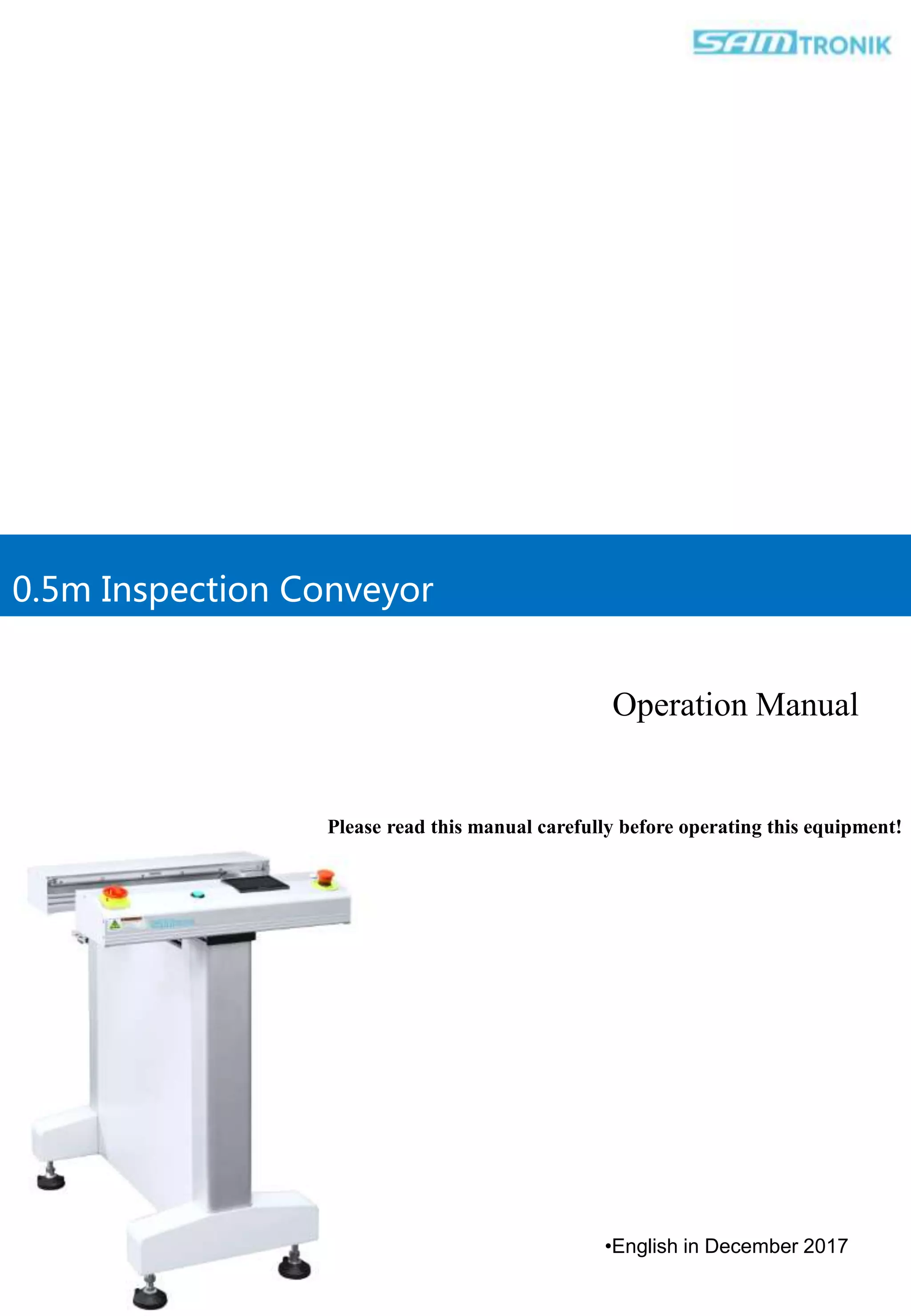
The manual outlines safety procedures, technical specifications, intended use, and operating instructions for a 0.5m Inspection Conveyor manufactured by Samtronik International Limited. It describes pre-use preparations including level adjusting, air supply, and power supply requirements. The manual also provides abbreviations used and explains that the conveyor is intended to transfer PCBs from an upstream to a downstream machine on a production line.