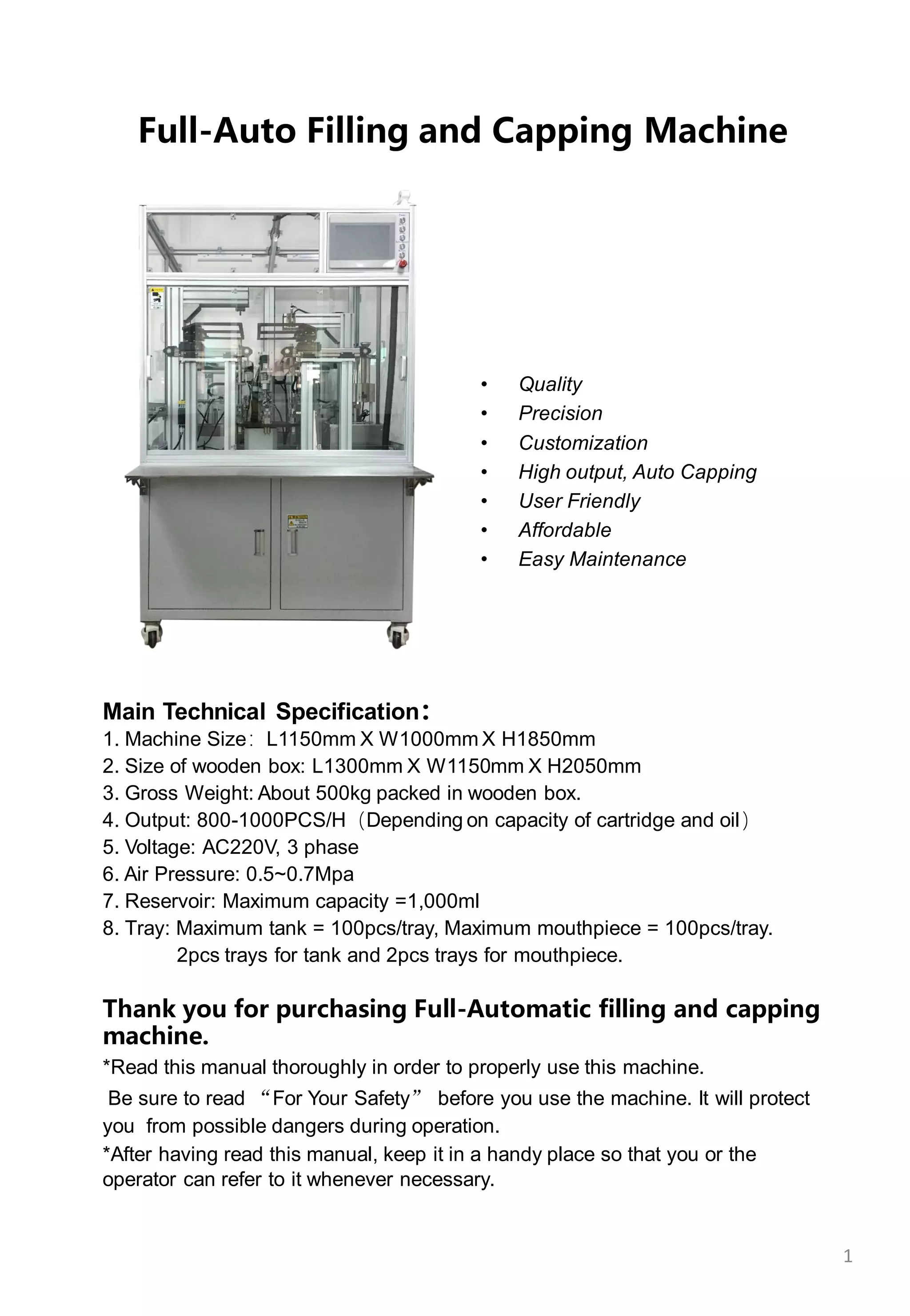
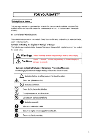
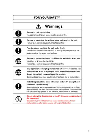
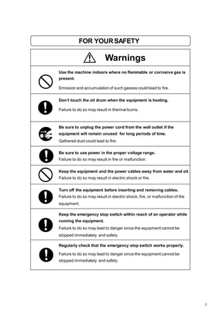
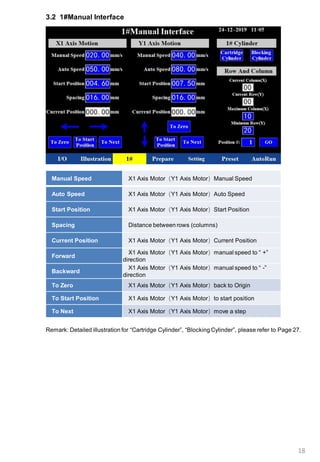
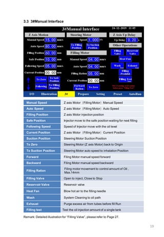
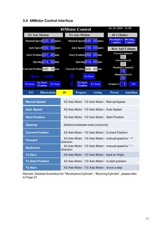
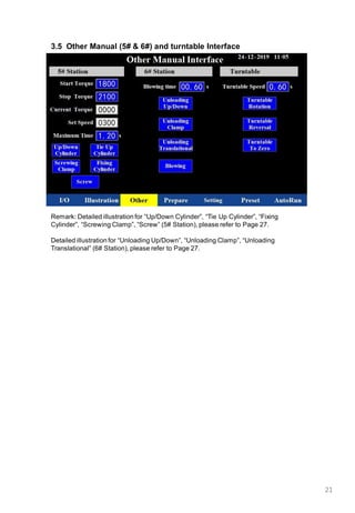
1
Full-Auto Filling and Capping Machine
Main Technical Specification:
1. Machine Size:L1150mm X W1000mm X H1850mm
2. Size of wooden box: L1300mm X W1150mm X H2050mm
3. Gross Weight: About 500kg packed in wooden box.
4. Output: 800-1000PCS/H(Depending on capacity of cartridge and oil)
5. Voltage: AC220V, 3 phase
6. Air Pressure: 0.5~0.7Mpa
7. Reservoir: Maximum capacity =1,000ml
8. Tray: Maximum tank = 100pcs/tray, Maximum mouthpiece = 100pcs/tray.
2pcs trays for tank and 2pcs trays for mouthpiece.
Thank you for purchasing Full-Automatic filling and capping
machine.
*Read this manual thoroughly in order to properly use this machine.
Be sure to read “For Your Safety” before you use the machine. It will protect
you from possible dangers during operation.
*After having read this manual, keep it in a handy place so that you or the
operator can refer to it whenever necessary.
• Quality
• Precision
• Customization
• High output, Auto Capping
• User Friendly
• Affordable
• Easy Maintenance
FOR YOURSAFETY
Safety Precautions
The precautions stated in this manual are provided for the customer to make the best use of this
product safely, and to provide preventive measures against injury to the customer or damage to
property.
Be sure to follow the instructions
Various symbols are used in this manual. Please read the following explanations to understand what
each symbol stands for.
Symbols indicating the Degree of Damage or Danger
The following symbols indicate the degree of damage or danger which may be incurred if you neglect
the safety notes.
Cautions
These “Cautions” indicate the possibility of accidental injury or
damage to property.
Warnings These “Warnings”indicatethe possibilityof death or serious injury.
Symbolsindicatingthetype of Danger and PreventiveMeasures
The followingsymbolsindicatethe typeof safety measurethatshouldbetaken.
Indicatesthetype of safetymeasurethatshouldbe taken.
Take care. (Generalcaution)
Indicatesprohibition.
Never dothis.(general prohibition)
Do not disassemble,modifyorrepair.
Do not touch.(contactprohibition)
Indicatesnecessity
Be sureto followinstructions.
Be sureto unplugpowersupplyfrom walloutlet.
Be sureto checkgrounding.
2
FOR YOURSAFETY
Warnings
Be sure to check grounding.
Improper grounding can cause electric shock or fire.
Be sure to use within the voltage range indicated on the unit.
Failure to do so may cause electric shock or fire.
Plug the power cord into the wall outlet firmly.
Failure to do so can cause the input to heat up and may result in fire.
Make sure that the power plug is clean.
Be sure to unplug the power cord from the wall outlet when you
examine or grease the machine.
Failure to do so may cause electric shock or fire.
Stop operation and unplug immediately whenever you sense any
abnormalities, such as a pungent odor. Immediately contact the
dealer from which you purchased the product.
Continued operation may result in electric shock, fire or malfunction.
Install the product in a place which can endure it’s weight and
conditions while running.
Be sure to leave a space greater than 30cm between the back of the
equipment and the wall. Installation in an insufficient or unstable place
can cause the equipment to fall, overturn, breakdown, or overheat.
Do not attempt to disassemble or modify the core components of
the equipment.
Disassemblyor modificationmay cause electric shocks, fire or
malfunction, no after-sales service will be provided either.
3
FOR YOURSAFETY
Warnings
Use the machine indoors where no flammable or corrosive gas is
present.
Emission and accumulation of such gasses could lead to fire.
Don’t touch the oil drum when the equipment is heating.
Failure to do so may result in thermal burns.
Be sure to unplug the power cord from the wall outlet if the
equipment will remain unused for long periods of time.
Gathered dust could lead to fire.
Be sure to use power in the proper voltage range.
Failure to do so may result in fire or malfunction.
Keep the equipment and the power cables away from water and oil.
Failure to do so may result in electric shock or fire.
Turn off the equipment before inserting and removing cables.
Failure to do so may result in electric shock, fire, or malfunction of the
equipment.
Keep the emergency stop switch within reach of an operator while
running the equipment.
Failure to do so may lead to danger since the equipment cannot be
stopped immediately and safely.
Regularly check that the emergency stop switch works properly.
Failure to do so may lead to danger since the equipment cannot be
stopped immediately and safely.
4
FOR YOURSAFETY
Cautions
Be sure to check grounding.
Improper grounding may cause malfunction or defect.
Use the machine in an environment between 0 to 40 degrees
centigrade with a humidity of 20 to 95 percent without
condensation.
Failure to do so may result in malfunction.
Use the machine in an environment where no electric noise is
present.
Failure to do so may result in malfunctionor defect.
Use the machine in an environment where it is not exposed to
direct sunlight.
Failure to do so may result in malfunctionor defect.
Be sure to confirm that tools such as the electric screwdriver unit,
etc. are properly connected.
Failure to do so may result in injury or defect.
Check the mounting screws regularly so that they are always
firmly tightened.
Loose screws may cause injury or defect.
Be sure to check the wiring to the main unit.
Improper wiring may cause malfunction or defect.
Be sure to secure the movable parts of the equipment before
transportation.
Failure to do so may result in defect or injury.
Do not bump or jar the machine while it is being transported or
installed.
This can cause defects.
5
6
CONTENTS
1. Operation Guideline and Preparations
1.1 Work Flow-----------------------------------------------------7
1.2 Machine Placement-------------------------------------------8
1.3 Power and Air Supply-----------------------------------------8
1.4 Manual Switch/Fiber Amplifier--------------------------------9
1.5 Installing and Testing--------------------------------------10-13
2. Operation Instruction
2.1 Wash----------------------------------------------------------14
2.2 Complete all the preparations--------------------------------14
2.3 Reset----------------------------------------------------------14
2.4 Auto-Start ----------------------------------------------------14
2.5 Material Cleaning---------------------------------------------15
2.6 Wash after production----------------------------------------15
2.7 Replacing Fixture/Jig -----------------------------------------16
3. Operation Interface
3.1 Startup picture-AutoRun Interface ---------------------------17
3.2 ①Manual Interface-------------------------------------------18
3.3 ③Manual Interface-------------------------------------------19
3.4 ④Manual Interface-------------------------------------------20
3.5 Other Manual(5# 6#) Interface-----------------------------21
3.6 IO------------------------------------------------------------22
3.7 Preset--------------------------------------------------------23
3.8 Setting-------------------------------------------------------24
3.9 PLC Wifi Setting----------------------------------------------25
3.10 Prepare ------------------------------------------------------26
3.11 Illustration for 1#Station & 3#Station, 4#Station, 5#Station &
6#Station---------------------------------------------------------27
4. Troubleshooting ---------------------------------------------28-29
5. Accessories and Spare Parts-------------------------------------30
6. Care and Maintenance ------------------------------------------31
1. Operation Guideline and Preparations
1.1 Work Flow
Unpack and Inspection
Machine WorkingZone
Power and Air Supply
Preparations---Installing, Testing, etc.
Washing Oil Path
7
Auto Run Filling and Capping
8
1.3 Power and Air Supply
1.3.1 Connect Power cord and Air Pipe
1.3.2 Power supply for filling machine: AC220V, 3-phase, check to make sure your
machine has the correct voltage for your local supply. Please be consulted by an
electrician if you are not familiar with this type of connection.
Air Pressure: 0.5-0.7Mpa.
Air Valve(blue parts), to the left is to Close, to the right is to Open.
Air Intake
1.2 Machine Placement
Our Full-automatic filling machine was thoroughly inspected before it was
delivered and should be ready to operate as soon as you have completed
the Installing and Set-up procedure.
Unpack the machine carefully to prevent loss of small items.
Set the machine base up at the clean and dust-free place.
Turning red nob anticlockwise to lock machine from movement, turning
clockwise to unlock machine for relocation.
Regulator
Air Valve Pressure gauge
Filling Machine
Power
Lock Ring
9
1.4 Manual Switch
1.4.1 Power, Start, Stop, Auto/Manual, Reset, Emergency Stop.
1.4.2 Oil Drum(Reservoir) Pressure, Valve Pressure, independent regulator.
Suggested Air Pressure: Oil Drum: 0.2MPa, Valve: 0.4MPa.
Pressure Gauge
1.4.3 Main Power Switch
To the Up is OFF, to the right is ON.
Regulator
1.4.4 Fiber Amplifier
Fiber Amplifieris to detect and sensor whether material is in position. Sensor
X33 is detecting workstation⑥ material readiness, X31 for workstation ①, X32 for
workstation①. B is pre-set from factory, C is current, when Current is bigger than
pre-set, A indicates red , material in right location; No indication in A, material not
in place.
BA C
Oil Drum = Reservoir
10
1.5.2 Tray use and replacement
1.5.1 Install Injector
At workstation#3, place injector① into holder, tighten screw. ② is a heating fan blowing
hot air to the injector in workstation#3,user can open the heating fan in the #3Manual
Interface.(How to enter into Interface refer to Chapter 3)
1.5.2.2 Load tanks: place 100pcs tanks over the tray with the filling port facing up. Each
time loading 2pcs trays into the machine.
1.5.2.1 Tray: Used to place tanks and mouthpieces, each machine equipped 4pcs trays for
tanks and 4pcs trays for mouthpieces.Each tray place 10X10pcs tanks(mouthpieces).
1.5.2.3 Load mouthpiece: each time loading 2pcs trays into the machine.
Left 2pcs tray loading tanks
1.5 Installation and Testing
②
①
Right 2pcs tray loading mouthpieces
D4 Tank and mouthpiece loading on tray V18 Tank and mouthpiece loading on tray
11
1.5.5 Check Emergency Stop switch on(Clockwise)
1.5.3 Filling Reservoir:
Follow the video to install reservoir to base, connect air pipe in reservoir and OUT2 plug.
Open cover of reservoir①, pour oil(or water when perform wash operation) in at certain
amount, capacity 1L, no more than 1L!!!
② is the switch to release reservoir and the base, upwards is to open.
When running “Wash“operation, the blue air valve③ must be opened downwards, see the
position shown.
Note: Fill pre-heated oil to reservoir if the oil is too thick.
Don’t touch reservoir during heating.
System will alert for low Oil level, then follow above procedure to fill oil.
②
①
1.5.6 Click “Setting“ interface, find ”Temperature“, set “SV”, thicker the Oil, higher the
temperature, it may vary depending on the viscosity of oil. Suggested “SV”: 60℃ for
reservoir, 70℃ for pump in, oil pump, pump out and inject valve.(Click on PV or SV
to switch between Celsius and Fahrenheit). Then click the middle “ON” of Heater.
Reservoir, pump in, oil pump, pump out and inject valve will be heated automatically.
After heating, the background color of PV for all 5 parts will change from light blue to
green , the description under Temperature will change from “Out of range” to “Within
range”, machine could reset and start working when temp. “Withinrange”. (How to
enter into Setting Interface please refer to Chapter 3.)
1.5.4 Power and Air Supply On.
③
Within range
12
1.5.8 Purge excess air from tubes before fill Run. Very Important: After reset the
machine for the first time, don’t start oiling before eliminate air through oil path.
(Place a cup under the needle to collect the oil.) Details please follow the video.
1.5.8.1 Select “Setting“, find “Preset Selection “, choose ”D4“ or ”V18“. Most key
parameters are listed in “Preset” interface, user can check and adjust if
necessary. (This procedure can be done after loading the trays or switching the
heater on.)
1.5.8.3 Long press “Air out 1sec.“ for 1 second.
1.5.8.4 Check needle for air traps until consistentoil flow, short press Stop to end
the procedure.
1.5.7 Reset
Before resetting the machine, make sure no tanks in any workstations,and all the
temp. “Within range”. Press the Reset button for 3 seconds and release, the indicator
light flickers, once the indicator light stay in yellow light means reset completed.If the
machine needs to be paused for any reason, short press reset once, machine will
“Pause”, press again the machine will continue with working process.
1.5.8.2 Change to “Prepare“ interface, find “Air out“, find ”Air out 1sec.“.
13
After purging air out, Reset the machine again. Enter into “Setting”, find “Filling Setting” .
1.5.9 Setting Filling Ration and Filling Test
Find “Filling Ration”, it is used to adjust oil volume per each injection, the greater number is,
the more oil volume. Max.14mm!!! 1mm=0.08ml Oil, it may vary based on oil viscosity.
Once Filing Ration set, place a D4 tank at workstation#2fixture, press “Filling Test”, the tank
will finish injection at workstation③, then move back to workstation②, take the tank out, please
verify Oil Volume until getting the required volume. Please refer the video for more details.
14
2. Operation Instruction
2.1 Wash the oil injection system
In order to avoid contaminations,it is recommended for the user to rinse the oil injection
system before testing and production.
Wash process instructions:
2.1.1 Remove injection needle.
2.1.2 Connect a long silicone tube.
2.1.3 Place a plastic container big enough at silicone tube outlet.
2.1.4 Fill reservoir with rinse fluid.
2.1.5 Secure reservoir cover with clamp.
2.1.6 Temperature is heated to “Within range”.
2.1.7 Open air valve on reservoir.(Slide blue air valve down)
2.1.8 Hold silicone tube while running wash.
2.1.9 Reset the machine.
2.1.10 Long press “Wash” to run rinse fluid.
2.1.11 Short press “Wash”to end the procedure.
2.4 Press Auto, then Press Start, the machine will run in AutoRun mode. The
completed filled and capped tanks will come out from the following outlet. Please use a soft
container to place these completed cartridges, in case scratched or bruised . And take out the
completed cartridges every once in a while.
Control unit for unloading conveyor belt
2.3 Reset the machine(Note: No materials should be in any one of 6 stations before
Reset, all temperature must achieve “Within range). And check if you require to open the
heating fan of the machine(at 3#Manual Interface).(Please refer the video for more details.)
2.2 Exhaust air from the oil path, Preset Selection(D4 or V18), Set Filling
Ration and Test filling volume for one tank. For more details please kindly check
all the videos one by one. After all the preparations and testing are completed, user can go on
to the following mass production.
15
2.5 Material Clearing
Once the tank tray is complete and machine stopped, press Stop button, then press
Reset button, the work of tanks and mouthpiecesin 6 workstationswill be finished and
emptied, no tank(mouthpiece) in workstationsin order to Reset machine for next cycle.
2.6 Wash again after production completed.
Details please refer to 2.1 and below.
Replace injector with silicon tube, other end connects to a big tank, fill reservoir with warm
water at 60-70℃(or using ethanol), open air valve in reservoir( Interface: enter into “Prepare “,
long press “Wash1sec.“ for 1 second for cleaning cycle. When cleaning completed, no more
flowing water from silicon tube, fill with water continue cleaning until cleaned, short press “Stop“
again to stop and re-intall injector for next operation.
16
2.7 Replacing Fixture/Jig
2.7.1 Fixture/Jig for D4/V18 at No.1,2,3,4,5,6 workstations. Firstly, check inner part of fixtures
for 6 workstations are the right ones for filling, if not, please follow our video to replace the
correct inner part to the fixtures.
Click “Turntable To Zero”at Setting interface to rotate the turntable, unscrew all the screws at
the bottom of the fixtures at workstation No.2(enough space), then the operator could replace all
the inner parts of fixtures at No.2 workstation, after completed the operator tighten all the
screws of the fixtures at workstation No.2.
Please kindly note that the machine was installed the fixtures of D4 at manufacturer’s factory.
inner part of fixtures for V18
① Unscrew all the screws of fixtures at # 2
③ Tighten all the screws at # 2
② Replace all the inner part of
fixtures at workstation 2
2.7.2 Three clamp jaws for work holding fixture at No.5 workstation.
Following the video to install the corresponding clamps.
For the air hose in below figure, already providing spare parts to customer.
2.7.3 Kindly note: Double check and make sure you have installed the correct
fixture/jig/parts before auto run filling.
Air hose
17
3.Operation Interface
3.1 Startup picture-AutoRun interface
Turn on the power switch to display AutoRun interface. This interface is for user to
check all the working status in Status window, oil level, temperature and
output/Efficency etc.during the AutoRun.
In this machine, there are 6 workstations in the turntable.The workstation 2 has
no special function, only providing enough space for user to operate and check
the working status of the turntable.
So, in the following interface, there is no interface for #2.
Indicator light on the top
Green: normal operations
Red: abnormal condition
Yellow: after reset condition
1. Status window will show the working status of the machine, failures and timing occurred.
2. Oil Level window will show the oil level and alert when there is in low oil level.
3. Temperature: “Out of range” or “Within range”
Heater: The first “off/on” indicates its status---change between on or off.
The second “ON” and third “OFF” are the control switch to make the heater on/off.
18
3.2 1#Manual Interface
Manual Speed X1 Axis Motor(Y1 Axis Motor)Manual Speed
Auto Speed X1 Axis Motor(Y1 Axis Motor)Auto Speed
Start Position X1 Axis Motor(Y1 Axis Motor)Start Position
Spacing Distance between rows (columns)
Current Position X1 Axis Motor(Y1 Axis Motor)Current Position
Forward
X1 Axis Motor(Y1 Axis Motor)manual speed to “ +”
direction
Backward
X1 Axis Motor(Y1 Axis Motor)manual speed to “ -”
direction
To Zero X1 Axis Motor(Y1 Axis Motor)back to Origin
To Start Position X1 Axis Motor(Y1 Axis Motor)to start position
To Next X1 Axis Motor(Y1 Axis Motor)move a step
Remark: Detailed illustration for “Cartridge Cylinder”, “Blocking Cylinder”, please refer to Page 27.
19
3.3 3#Manual Interface
Manual Speed Z axis Motor(Filling Motor)Manual Speed
Auto Speed Z axis Motor(Filling Motor)Auto Speed
Filling Position Z axis Motor injection position
Safe Position Injector move to the safe position waiting for next filling
Following Speed Speed of Injector move with the oil level
Current Position Z axis Motor(Filling Motor)Current Position
Suction Position Steering Motor Suction Position
To Zero Steering Motor (Z axis Motor) back to Origin
To Suction Position Steering Motor auto speed to inhalation Position
Forward Filing Motor manual speed forward
Backward Filing Motor manual speed backward
Filling Ration
Filing motor movement to control amount of Oil ,
Max.14mm
Filling Valve Open to inject, Close to Stop
Reservoir Valve Reservoir valve
Heat Fan Blow hot air to the filling needle
Wash System Cleaning to oil path
Exhaust Purge excess air from tubes before fill Run
Filling test Test the oil injection amount of a single tank
Remark: Detailed illustration for “Filling Valve”, please refer to Page 27.
20
3.4 4#Motor Control Interface
Manual Speed X2 Axis Motor(Y2 Axis Motor)Manual Speed
Auto Speed X2 Axis Motor(Y2 Axis Motor)Auto Speed
Start Position X2 Axis Motor(Y2 Axis Motor)Start Position
Spacing Distance between rows (columns)
Current Position X2 Axis Motor(Y2 Axis Motor)Current Position
Forward
X2 Axis Motor(Y2 Axis Motor)manual speed to “ +”
direction
Backward
X2 Axis Motor(Y2 Axis Motor)manual speed to “ -”
direction
To Zero X2 Axis Motor(Y2 Axis Motor)back to Origin
To Start Position X2 Axis Motor(Y2 Axis Motor)to start position
To Next X2 Axis Motor(Y2 Axis Motor)move a step
Remark: Detailed illustration for “Mouthpiece Cylinder”, “Blocking Cylinder”, please refer
to Page 27.
21
3.5 Other Manual (5# & 6#) and turntable Interface
Remark: Detailed illustration for “Up/Down Cylinder”, “Tie Up Cylinder”, “Fixing
Cylinder”, “Screwing Clamp”, “Screw” (5# Station), please refer to Page 27.
Detailed illustration for “Unloading Up/Down”, “Unloading Clamp”, “Unloading
Translational” (6# Station), please refer to Page 27.
22
3.6 I/O Interface: red indicator light will indicate input or output.
23
3.7 Preset Interface
24
3.8 Setting
Long press on the time in the top right corner to edit the time and date.
Heating “ON”
Reservoir, pump in, oil pump, pump out and inject valve all
heat at the same time.
PV and SV
Click on PV or SV to switch between Celsius and
Fahrenheit
Filling Ration
Oiling motor movement to control amount of Oil ,
Max.14mm
Filing Prohibit No injection, machine adjustment only
Filling Test
Test the oil injection amount of a single cartridge in station
No. 3
Wash System Cleaning to oil path
Exhaust Purge excess air from tubes before fill Run
Turntable To Zero Turntable, counter clockwiseone step
25
3.9 PLC Wifi Setting
This is a new feature for remote online control.
26
3.10 Prepare
27
3.11 Illustration for 1#Station & 3#Station, 4#Station, 5#Station & 6#Station
28
4. Troubleshooting
Failures Solutions
Outer Drum High Temperature Alarm The temperature of outer drum is over 220℃, waiting for cooling down.
Stopping Overtime
It should be caused by operation error. Press the emergency stop button
and reset the machine.
Resetting Overtime
X32 Cartridge Induction Abnormal(1#
Station)
Check if there is a cartridge in #1station, no cartridge means abnormal.
Oil Drum Low Level Alarm(Filling Station) There is not much oil left, If you want to continue working, add oil to drum.
X33 Cartridge Induction Abnormal(6#
Station)
Check if there is cartridge in #6station, remove it and it will turnto normal.
Unloading Translational Cylinder Induction
Abnormal(6# Station)
Check whether the cartridge is stuck at #6station.
X31 Mouthpiece Induction Abnormal(4#
Station)
Check whether the mouthpiece is stuck at #6station.
1#Complete All, Please Change the Cartridge
Tray or Click the "Stop" Button
1#Complete All, Please Change the Cartridge Tray or Click the "Stop"
Button
Cartridge Cylinder Induction Abnormal(1#
Station)
Induction is abnormal.
1. Check if the cylinder is in place (check if the air pressure is sufficient)
2. Check if the I/O has input and output. If there is no output, check if the
sensor is loose and the light is not on.
3. Check if the solenoid valve is broken
Mouthpiece Cylinder Induction Abnormal(4#
Station)
Pushing Cylinder Induction Abnormal(4#
Station)
Pressing Cylinder Induction Abnormal(4#
Station)
Mouthpiece Fixing Cylinder Induction
Abnormal(4# Station)
Up/Down Cylinder Induction Abnormal(5#
Station)
Mouthpiece Fixing Cylinder Induction
Abnormal(5# Station)
Unloading Up/Down Cylinder Induction
Abnormal(6# Station)
4#Complete All, Please Replace the
Mouthpiece Tray
4#Complete All, Please Change the Mouthpiece Tray
1#Overtime
Check if there is any abnormality in the No.1 station cylinder and whether
the X32 sensor is correct.
3#Overtime
Check whether the cylinder of the No. 3 station is abnormal, whether the
oiling station is working normally, and whether the oil temperature is
normal.
4#Overtime
Check if there is any abnormality in the No. 4 station cylinder and whether
the X31 sensor is correct.
5#Overtime Check if there is any abnormality in the No. 5 station cylinder.
6#Overtime
Check if there is any abnormality in the No. 6 station cylinder and whether
the X33 sensor is correct.
Filling Prohibit Remind the operator that the oil has been banned
All the failures below will be showed at Status window in “AutoRun” interface, please kindly check and solve
the problems according to the list below.
29
Troubleshooting
Failures Solutions
Turntable Overtime
Check if the speed setting is normal
X1 Axis Motor Overtime(1# Station)
Y1 Axis Motor Overtime(1# Station)
Z Axis Motor Overtime(3# Station)
X2 Axis Motor Overtime(4# Station)
Y2 Axis Motor Overtime(4# Station)
Steering Motor Overtime(3#Filling
Station)
Filling Motor Overtime(3#Filling
Station)
Temperature Alarm(Filling Station)
Temperature has not reached the setting temperature and can be operated
after the temperature is reached.
Test Run With Null Running, For Test
Emergency Stop Emergency stop
Z Axis Motor Alarm
Drive alarm, restart the machine
Screw Motor Alarm
Mouthpiece Loss Take out the cartridge of workstation 6, reset
The Turntable Is Not At Its Origin Reset the turntable
Spare Part QTY
D4 Fixture 1set
V18-0.5ml Fixture 1set
Loading Tray for tanks 4sets
Loading Tray for mouthpiece 4sets
clamp jaws for work holding
fixture at No.5 workstation
1pc
Metal sleeve at No.4 workstation 1pc
Reservoir 1pc
Toolkit 1pc
Injector (20g) 10pcs
Phillips Screw Driver 1pc
Screw Driver 1pc
Allan Wrench 1set
Fixed Wrench 2pcs
Silicone Cleaning Pipe 1pc
Vulnerable sealing ring 5pcs
Air hose and other small parts
5. Accessories and Spare Parts
30
6.1 Keep unit clean after each production.
6.2 Check the rails regularly for lubricant.
6.3 When unit is not in use, clean all pipes, and turn off power supply
and air source.
6. Care and Maintenance
31

Buddy High Volume Filling and Capping Machines

  • 1.
    1 Full-Auto Filling andCapping Machine Main Technical Specification: 1. Machine Size:L1150mm X W1000mm X H1850mm 2. Size of wooden box: L1300mm X W1150mm X H2050mm 3. Gross Weight: About 500kg packed in wooden box. 4. Output: 800-1000PCS/H(Depending on capacity of cartridge and oil) 5. Voltage: AC220V, 3 phase 6. Air Pressure: 0.5~0.7Mpa 7. Reservoir: Maximum capacity =1,000ml 8. Tray: Maximum tank = 100pcs/tray, Maximum mouthpiece = 100pcs/tray. 2pcs trays for tank and 2pcs trays for mouthpiece. Thank you for purchasing Full-Automatic filling and capping machine. *Read this manual thoroughly in order to properly use this machine. Be sure to read “For Your Safety” before you use the machine. It will protect you from possible dangers during operation. *After having read this manual, keep it in a handy place so that you or the operator can refer to it whenever necessary. • Quality • Precision • Customization • High output, Auto Capping • User Friendly • Affordable • Easy Maintenance
  • 2.
    FOR YOURSAFETY Safety Precautions Theprecautions stated in this manual are provided for the customer to make the best use of this product safely, and to provide preventive measures against injury to the customer or damage to property. Be sure to follow the instructions Various symbols are used in this manual. Please read the following explanations to understand what each symbol stands for. Symbols indicating the Degree of Damage or Danger The following symbols indicate the degree of damage or danger which may be incurred if you neglect the safety notes. Cautions These “Cautions” indicate the possibility of accidental injury or damage to property. Warnings These “Warnings”indicatethe possibilityof death or serious injury. Symbolsindicatingthetype of Danger and PreventiveMeasures The followingsymbolsindicatethe typeof safety measurethatshouldbetaken. Indicatesthetype of safetymeasurethatshouldbe taken. Take care. (Generalcaution) Indicatesprohibition. Never dothis.(general prohibition) Do not disassemble,modifyorrepair. Do not touch.(contactprohibition) Indicatesnecessity Be sureto followinstructions. Be sureto unplugpowersupplyfrom walloutlet. Be sureto checkgrounding. 2
  • 3.
    FOR YOURSAFETY Warnings Be sureto check grounding. Improper grounding can cause electric shock or fire. Be sure to use within the voltage range indicated on the unit. Failure to do so may cause electric shock or fire. Plug the power cord into the wall outlet firmly. Failure to do so can cause the input to heat up and may result in fire. Make sure that the power plug is clean. Be sure to unplug the power cord from the wall outlet when you examine or grease the machine. Failure to do so may cause electric shock or fire. Stop operation and unplug immediately whenever you sense any abnormalities, such as a pungent odor. Immediately contact the dealer from which you purchased the product. Continued operation may result in electric shock, fire or malfunction. Install the product in a place which can endure it’s weight and conditions while running. Be sure to leave a space greater than 30cm between the back of the equipment and the wall. Installation in an insufficient or unstable place can cause the equipment to fall, overturn, breakdown, or overheat. Do not attempt to disassemble or modify the core components of the equipment. Disassemblyor modificationmay cause electric shocks, fire or malfunction, no after-sales service will be provided either. 3
  • 4.
    FOR YOURSAFETY Warnings Use themachine indoors where no flammable or corrosive gas is present. Emission and accumulation of such gasses could lead to fire. Don’t touch the oil drum when the equipment is heating. Failure to do so may result in thermal burns. Be sure to unplug the power cord from the wall outlet if the equipment will remain unused for long periods of time. Gathered dust could lead to fire. Be sure to use power in the proper voltage range. Failure to do so may result in fire or malfunction. Keep the equipment and the power cables away from water and oil. Failure to do so may result in electric shock or fire. Turn off the equipment before inserting and removing cables. Failure to do so may result in electric shock, fire, or malfunction of the equipment. Keep the emergency stop switch within reach of an operator while running the equipment. Failure to do so may lead to danger since the equipment cannot be stopped immediately and safely. Regularly check that the emergency stop switch works properly. Failure to do so may lead to danger since the equipment cannot be stopped immediately and safely. 4
  • 5.
    FOR YOURSAFETY Cautions Be sureto check grounding. Improper grounding may cause malfunction or defect. Use the machine in an environment between 0 to 40 degrees centigrade with a humidity of 20 to 95 percent without condensation. Failure to do so may result in malfunction. Use the machine in an environment where no electric noise is present. Failure to do so may result in malfunctionor defect. Use the machine in an environment where it is not exposed to direct sunlight. Failure to do so may result in malfunctionor defect. Be sure to confirm that tools such as the electric screwdriver unit, etc. are properly connected. Failure to do so may result in injury or defect. Check the mounting screws regularly so that they are always firmly tightened. Loose screws may cause injury or defect. Be sure to check the wiring to the main unit. Improper wiring may cause malfunction or defect. Be sure to secure the movable parts of the equipment before transportation. Failure to do so may result in defect or injury. Do not bump or jar the machine while it is being transported or installed. This can cause defects. 5
  • 6.
    6 CONTENTS 1. Operation Guidelineand Preparations 1.1 Work Flow-----------------------------------------------------7 1.2 Machine Placement-------------------------------------------8 1.3 Power and Air Supply-----------------------------------------8 1.4 Manual Switch/Fiber Amplifier--------------------------------9 1.5 Installing and Testing--------------------------------------10-13 2. Operation Instruction 2.1 Wash----------------------------------------------------------14 2.2 Complete all the preparations--------------------------------14 2.3 Reset----------------------------------------------------------14 2.4 Auto-Start ----------------------------------------------------14 2.5 Material Cleaning---------------------------------------------15 2.6 Wash after production----------------------------------------15 2.7 Replacing Fixture/Jig -----------------------------------------16 3. Operation Interface 3.1 Startup picture-AutoRun Interface ---------------------------17 3.2 ①Manual Interface-------------------------------------------18 3.3 ③Manual Interface-------------------------------------------19 3.4 ④Manual Interface-------------------------------------------20 3.5 Other Manual(5# 6#) Interface-----------------------------21 3.6 IO------------------------------------------------------------22 3.7 Preset--------------------------------------------------------23 3.8 Setting-------------------------------------------------------24 3.9 PLC Wifi Setting----------------------------------------------25 3.10 Prepare ------------------------------------------------------26 3.11 Illustration for 1#Station & 3#Station, 4#Station, 5#Station & 6#Station---------------------------------------------------------27 4. Troubleshooting ---------------------------------------------28-29 5. Accessories and Spare Parts-------------------------------------30 6. Care and Maintenance ------------------------------------------31
  • 7.
    1. Operation Guidelineand Preparations 1.1 Work Flow Unpack and Inspection Machine WorkingZone Power and Air Supply Preparations---Installing, Testing, etc. Washing Oil Path 7 Auto Run Filling and Capping
  • 8.
    8 1.3 Power andAir Supply 1.3.1 Connect Power cord and Air Pipe 1.3.2 Power supply for filling machine: AC220V, 3-phase, check to make sure your machine has the correct voltage for your local supply. Please be consulted by an electrician if you are not familiar with this type of connection. Air Pressure: 0.5-0.7Mpa. Air Valve(blue parts), to the left is to Close, to the right is to Open. Air Intake 1.2 Machine Placement Our Full-automatic filling machine was thoroughly inspected before it was delivered and should be ready to operate as soon as you have completed the Installing and Set-up procedure. Unpack the machine carefully to prevent loss of small items. Set the machine base up at the clean and dust-free place. Turning red nob anticlockwise to lock machine from movement, turning clockwise to unlock machine for relocation. Regulator Air Valve Pressure gauge Filling Machine Power Lock Ring
  • 9.
    9 1.4 Manual Switch 1.4.1Power, Start, Stop, Auto/Manual, Reset, Emergency Stop. 1.4.2 Oil Drum(Reservoir) Pressure, Valve Pressure, independent regulator. Suggested Air Pressure: Oil Drum: 0.2MPa, Valve: 0.4MPa. Pressure Gauge 1.4.3 Main Power Switch To the Up is OFF, to the right is ON. Regulator 1.4.4 Fiber Amplifier Fiber Amplifieris to detect and sensor whether material is in position. Sensor X33 is detecting workstation⑥ material readiness, X31 for workstation ①, X32 for workstation①. B is pre-set from factory, C is current, when Current is bigger than pre-set, A indicates red , material in right location; No indication in A, material not in place. BA C Oil Drum = Reservoir
  • 10.
    10 1.5.2 Tray useand replacement 1.5.1 Install Injector At workstation#3, place injector① into holder, tighten screw. ② is a heating fan blowing hot air to the injector in workstation#3,user can open the heating fan in the #3Manual Interface.(How to enter into Interface refer to Chapter 3) 1.5.2.2 Load tanks: place 100pcs tanks over the tray with the filling port facing up. Each time loading 2pcs trays into the machine. 1.5.2.1 Tray: Used to place tanks and mouthpieces, each machine equipped 4pcs trays for tanks and 4pcs trays for mouthpieces.Each tray place 10X10pcs tanks(mouthpieces). 1.5.2.3 Load mouthpiece: each time loading 2pcs trays into the machine. Left 2pcs tray loading tanks 1.5 Installation and Testing ② ① Right 2pcs tray loading mouthpieces D4 Tank and mouthpiece loading on tray V18 Tank and mouthpiece loading on tray
  • 11.
    11 1.5.5 Check EmergencyStop switch on(Clockwise) 1.5.3 Filling Reservoir: Follow the video to install reservoir to base, connect air pipe in reservoir and OUT2 plug. Open cover of reservoir①, pour oil(or water when perform wash operation) in at certain amount, capacity 1L, no more than 1L!!! ② is the switch to release reservoir and the base, upwards is to open. When running “Wash“operation, the blue air valve③ must be opened downwards, see the position shown. Note: Fill pre-heated oil to reservoir if the oil is too thick. Don’t touch reservoir during heating. System will alert for low Oil level, then follow above procedure to fill oil. ② ① 1.5.6 Click “Setting“ interface, find ”Temperature“, set “SV”, thicker the Oil, higher the temperature, it may vary depending on the viscosity of oil. Suggested “SV”: 60℃ for reservoir, 70℃ for pump in, oil pump, pump out and inject valve.(Click on PV or SV to switch between Celsius and Fahrenheit). Then click the middle “ON” of Heater. Reservoir, pump in, oil pump, pump out and inject valve will be heated automatically. After heating, the background color of PV for all 5 parts will change from light blue to green , the description under Temperature will change from “Out of range” to “Within range”, machine could reset and start working when temp. “Withinrange”. (How to enter into Setting Interface please refer to Chapter 3.) 1.5.4 Power and Air Supply On. ③ Within range
  • 12.
    12 1.5.8 Purge excessair from tubes before fill Run. Very Important: After reset the machine for the first time, don’t start oiling before eliminate air through oil path. (Place a cup under the needle to collect the oil.) Details please follow the video. 1.5.8.1 Select “Setting“, find “Preset Selection “, choose ”D4“ or ”V18“. Most key parameters are listed in “Preset” interface, user can check and adjust if necessary. (This procedure can be done after loading the trays or switching the heater on.) 1.5.8.3 Long press “Air out 1sec.“ for 1 second. 1.5.8.4 Check needle for air traps until consistentoil flow, short press Stop to end the procedure. 1.5.7 Reset Before resetting the machine, make sure no tanks in any workstations,and all the temp. “Within range”. Press the Reset button for 3 seconds and release, the indicator light flickers, once the indicator light stay in yellow light means reset completed.If the machine needs to be paused for any reason, short press reset once, machine will “Pause”, press again the machine will continue with working process. 1.5.8.2 Change to “Prepare“ interface, find “Air out“, find ”Air out 1sec.“.
  • 13.
    13 After purging airout, Reset the machine again. Enter into “Setting”, find “Filling Setting” . 1.5.9 Setting Filling Ration and Filling Test Find “Filling Ration”, it is used to adjust oil volume per each injection, the greater number is, the more oil volume. Max.14mm!!! 1mm=0.08ml Oil, it may vary based on oil viscosity. Once Filing Ration set, place a D4 tank at workstation#2fixture, press “Filling Test”, the tank will finish injection at workstation③, then move back to workstation②, take the tank out, please verify Oil Volume until getting the required volume. Please refer the video for more details.
  • 14.
    14 2. Operation Instruction 2.1Wash the oil injection system In order to avoid contaminations,it is recommended for the user to rinse the oil injection system before testing and production. Wash process instructions: 2.1.1 Remove injection needle. 2.1.2 Connect a long silicone tube. 2.1.3 Place a plastic container big enough at silicone tube outlet. 2.1.4 Fill reservoir with rinse fluid. 2.1.5 Secure reservoir cover with clamp. 2.1.6 Temperature is heated to “Within range”. 2.1.7 Open air valve on reservoir.(Slide blue air valve down) 2.1.8 Hold silicone tube while running wash. 2.1.9 Reset the machine. 2.1.10 Long press “Wash” to run rinse fluid. 2.1.11 Short press “Wash”to end the procedure. 2.4 Press Auto, then Press Start, the machine will run in AutoRun mode. The completed filled and capped tanks will come out from the following outlet. Please use a soft container to place these completed cartridges, in case scratched or bruised . And take out the completed cartridges every once in a while. Control unit for unloading conveyor belt 2.3 Reset the machine(Note: No materials should be in any one of 6 stations before Reset, all temperature must achieve “Within range). And check if you require to open the heating fan of the machine(at 3#Manual Interface).(Please refer the video for more details.) 2.2 Exhaust air from the oil path, Preset Selection(D4 or V18), Set Filling Ration and Test filling volume for one tank. For more details please kindly check all the videos one by one. After all the preparations and testing are completed, user can go on to the following mass production.
  • 15.
    15 2.5 Material Clearing Oncethe tank tray is complete and machine stopped, press Stop button, then press Reset button, the work of tanks and mouthpiecesin 6 workstationswill be finished and emptied, no tank(mouthpiece) in workstationsin order to Reset machine for next cycle. 2.6 Wash again after production completed. Details please refer to 2.1 and below. Replace injector with silicon tube, other end connects to a big tank, fill reservoir with warm water at 60-70℃(or using ethanol), open air valve in reservoir( Interface: enter into “Prepare “, long press “Wash1sec.“ for 1 second for cleaning cycle. When cleaning completed, no more flowing water from silicon tube, fill with water continue cleaning until cleaned, short press “Stop“ again to stop and re-intall injector for next operation.
  • 16.
    16 2.7 Replacing Fixture/Jig 2.7.1Fixture/Jig for D4/V18 at No.1,2,3,4,5,6 workstations. Firstly, check inner part of fixtures for 6 workstations are the right ones for filling, if not, please follow our video to replace the correct inner part to the fixtures. Click “Turntable To Zero”at Setting interface to rotate the turntable, unscrew all the screws at the bottom of the fixtures at workstation No.2(enough space), then the operator could replace all the inner parts of fixtures at No.2 workstation, after completed the operator tighten all the screws of the fixtures at workstation No.2. Please kindly note that the machine was installed the fixtures of D4 at manufacturer’s factory. inner part of fixtures for V18 ① Unscrew all the screws of fixtures at # 2 ③ Tighten all the screws at # 2 ② Replace all the inner part of fixtures at workstation 2 2.7.2 Three clamp jaws for work holding fixture at No.5 workstation. Following the video to install the corresponding clamps. For the air hose in below figure, already providing spare parts to customer. 2.7.3 Kindly note: Double check and make sure you have installed the correct fixture/jig/parts before auto run filling. Air hose
  • 17.
    17 3.Operation Interface 3.1 Startuppicture-AutoRun interface Turn on the power switch to display AutoRun interface. This interface is for user to check all the working status in Status window, oil level, temperature and output/Efficency etc.during the AutoRun. In this machine, there are 6 workstations in the turntable.The workstation 2 has no special function, only providing enough space for user to operate and check the working status of the turntable. So, in the following interface, there is no interface for #2. Indicator light on the top Green: normal operations Red: abnormal condition Yellow: after reset condition 1. Status window will show the working status of the machine, failures and timing occurred. 2. Oil Level window will show the oil level and alert when there is in low oil level. 3. Temperature: “Out of range” or “Within range” Heater: The first “off/on” indicates its status---change between on or off. The second “ON” and third “OFF” are the control switch to make the heater on/off.
  • 18.
    18 3.2 1#Manual Interface ManualSpeed X1 Axis Motor(Y1 Axis Motor)Manual Speed Auto Speed X1 Axis Motor(Y1 Axis Motor)Auto Speed Start Position X1 Axis Motor(Y1 Axis Motor)Start Position Spacing Distance between rows (columns) Current Position X1 Axis Motor(Y1 Axis Motor)Current Position Forward X1 Axis Motor(Y1 Axis Motor)manual speed to “ +” direction Backward X1 Axis Motor(Y1 Axis Motor)manual speed to “ -” direction To Zero X1 Axis Motor(Y1 Axis Motor)back to Origin To Start Position X1 Axis Motor(Y1 Axis Motor)to start position To Next X1 Axis Motor(Y1 Axis Motor)move a step Remark: Detailed illustration for “Cartridge Cylinder”, “Blocking Cylinder”, please refer to Page 27.
  • 19.
    19 3.3 3#Manual Interface ManualSpeed Z axis Motor(Filling Motor)Manual Speed Auto Speed Z axis Motor(Filling Motor)Auto Speed Filling Position Z axis Motor injection position Safe Position Injector move to the safe position waiting for next filling Following Speed Speed of Injector move with the oil level Current Position Z axis Motor(Filling Motor)Current Position Suction Position Steering Motor Suction Position To Zero Steering Motor (Z axis Motor) back to Origin To Suction Position Steering Motor auto speed to inhalation Position Forward Filing Motor manual speed forward Backward Filing Motor manual speed backward Filling Ration Filing motor movement to control amount of Oil , Max.14mm Filling Valve Open to inject, Close to Stop Reservoir Valve Reservoir valve Heat Fan Blow hot air to the filling needle Wash System Cleaning to oil path Exhaust Purge excess air from tubes before fill Run Filling test Test the oil injection amount of a single tank Remark: Detailed illustration for “Filling Valve”, please refer to Page 27.
  • 20.
    20 3.4 4#Motor ControlInterface Manual Speed X2 Axis Motor(Y2 Axis Motor)Manual Speed Auto Speed X2 Axis Motor(Y2 Axis Motor)Auto Speed Start Position X2 Axis Motor(Y2 Axis Motor)Start Position Spacing Distance between rows (columns) Current Position X2 Axis Motor(Y2 Axis Motor)Current Position Forward X2 Axis Motor(Y2 Axis Motor)manual speed to “ +” direction Backward X2 Axis Motor(Y2 Axis Motor)manual speed to “ -” direction To Zero X2 Axis Motor(Y2 Axis Motor)back to Origin To Start Position X2 Axis Motor(Y2 Axis Motor)to start position To Next X2 Axis Motor(Y2 Axis Motor)move a step Remark: Detailed illustration for “Mouthpiece Cylinder”, “Blocking Cylinder”, please refer to Page 27.
  • 21.
    21 3.5 Other Manual(5# & 6#) and turntable Interface Remark: Detailed illustration for “Up/Down Cylinder”, “Tie Up Cylinder”, “Fixing Cylinder”, “Screwing Clamp”, “Screw” (5# Station), please refer to Page 27. Detailed illustration for “Unloading Up/Down”, “Unloading Clamp”, “Unloading Translational” (6# Station), please refer to Page 27.
  • 22.
    22 3.6 I/O Interface:red indicator light will indicate input or output.
  • 23.
  • 24.
    24 3.8 Setting Long presson the time in the top right corner to edit the time and date. Heating “ON” Reservoir, pump in, oil pump, pump out and inject valve all heat at the same time. PV and SV Click on PV or SV to switch between Celsius and Fahrenheit Filling Ration Oiling motor movement to control amount of Oil , Max.14mm Filing Prohibit No injection, machine adjustment only Filling Test Test the oil injection amount of a single cartridge in station No. 3 Wash System Cleaning to oil path Exhaust Purge excess air from tubes before fill Run Turntable To Zero Turntable, counter clockwiseone step
  • 25.
    25 3.9 PLC WifiSetting This is a new feature for remote online control.
  • 26.
  • 27.
    27 3.11 Illustration for1#Station & 3#Station, 4#Station, 5#Station & 6#Station
  • 28.
    28 4. Troubleshooting Failures Solutions OuterDrum High Temperature Alarm The temperature of outer drum is over 220℃, waiting for cooling down. Stopping Overtime It should be caused by operation error. Press the emergency stop button and reset the machine. Resetting Overtime X32 Cartridge Induction Abnormal(1# Station) Check if there is a cartridge in #1station, no cartridge means abnormal. Oil Drum Low Level Alarm(Filling Station) There is not much oil left, If you want to continue working, add oil to drum. X33 Cartridge Induction Abnormal(6# Station) Check if there is cartridge in #6station, remove it and it will turnto normal. Unloading Translational Cylinder Induction Abnormal(6# Station) Check whether the cartridge is stuck at #6station. X31 Mouthpiece Induction Abnormal(4# Station) Check whether the mouthpiece is stuck at #6station. 1#Complete All, Please Change the Cartridge Tray or Click the "Stop" Button 1#Complete All, Please Change the Cartridge Tray or Click the "Stop" Button Cartridge Cylinder Induction Abnormal(1# Station) Induction is abnormal. 1. Check if the cylinder is in place (check if the air pressure is sufficient) 2. Check if the I/O has input and output. If there is no output, check if the sensor is loose and the light is not on. 3. Check if the solenoid valve is broken Mouthpiece Cylinder Induction Abnormal(4# Station) Pushing Cylinder Induction Abnormal(4# Station) Pressing Cylinder Induction Abnormal(4# Station) Mouthpiece Fixing Cylinder Induction Abnormal(4# Station) Up/Down Cylinder Induction Abnormal(5# Station) Mouthpiece Fixing Cylinder Induction Abnormal(5# Station) Unloading Up/Down Cylinder Induction Abnormal(6# Station) 4#Complete All, Please Replace the Mouthpiece Tray 4#Complete All, Please Change the Mouthpiece Tray 1#Overtime Check if there is any abnormality in the No.1 station cylinder and whether the X32 sensor is correct. 3#Overtime Check whether the cylinder of the No. 3 station is abnormal, whether the oiling station is working normally, and whether the oil temperature is normal. 4#Overtime Check if there is any abnormality in the No. 4 station cylinder and whether the X31 sensor is correct. 5#Overtime Check if there is any abnormality in the No. 5 station cylinder. 6#Overtime Check if there is any abnormality in the No. 6 station cylinder and whether the X33 sensor is correct. Filling Prohibit Remind the operator that the oil has been banned All the failures below will be showed at Status window in “AutoRun” interface, please kindly check and solve the problems according to the list below.
  • 29.
    29 Troubleshooting Failures Solutions Turntable Overtime Checkif the speed setting is normal X1 Axis Motor Overtime(1# Station) Y1 Axis Motor Overtime(1# Station) Z Axis Motor Overtime(3# Station) X2 Axis Motor Overtime(4# Station) Y2 Axis Motor Overtime(4# Station) Steering Motor Overtime(3#Filling Station) Filling Motor Overtime(3#Filling Station) Temperature Alarm(Filling Station) Temperature has not reached the setting temperature and can be operated after the temperature is reached. Test Run With Null Running, For Test Emergency Stop Emergency stop Z Axis Motor Alarm Drive alarm, restart the machine Screw Motor Alarm Mouthpiece Loss Take out the cartridge of workstation 6, reset The Turntable Is Not At Its Origin Reset the turntable
  • 30.
    Spare Part QTY D4Fixture 1set V18-0.5ml Fixture 1set Loading Tray for tanks 4sets Loading Tray for mouthpiece 4sets clamp jaws for work holding fixture at No.5 workstation 1pc Metal sleeve at No.4 workstation 1pc Reservoir 1pc Toolkit 1pc Injector (20g) 10pcs Phillips Screw Driver 1pc Screw Driver 1pc Allan Wrench 1set Fixed Wrench 2pcs Silicone Cleaning Pipe 1pc Vulnerable sealing ring 5pcs Air hose and other small parts 5. Accessories and Spare Parts 30
  • 31.
    6.1 Keep unitclean after each production. 6.2 Check the rails regularly for lubricant. 6.3 When unit is not in use, clean all pipes, and turn off power supply and air source. 6. Care and Maintenance 31