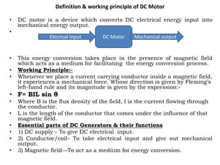
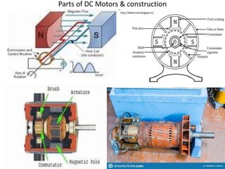
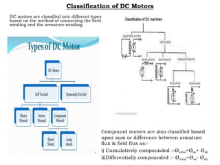
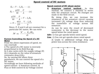
The document discusses DC motors, providing definitions, working principles, and components. It describes:
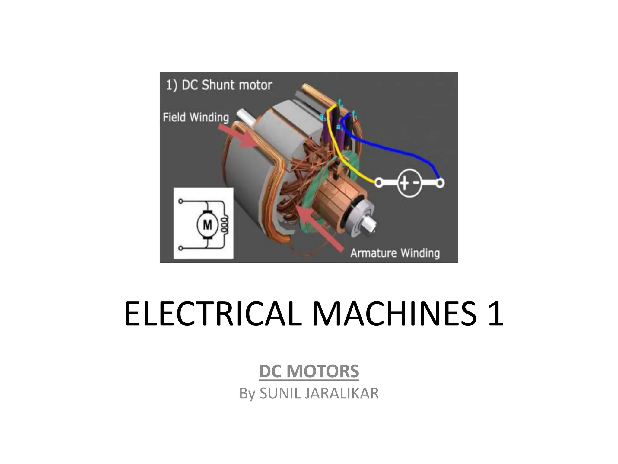
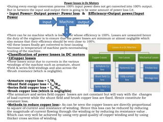
1) The key components of a DC motor include a DC supply, conductor/coil, and magnetic field. The magnetic field acts as a medium to convert electrical input into mechanical output.
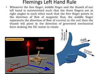
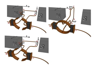
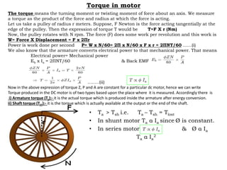
2) Fleming's left hand rule describes how the direction of generated force is determined based on the direction of current flow and magnetic flux.
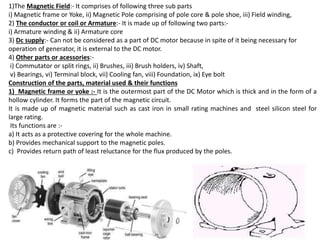
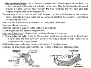
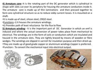
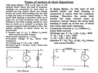
3) DC motors have several parts like magnetic poles, armature winding, commutator, and brushes that work together to convert electrical energy to rotational motion.
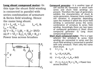
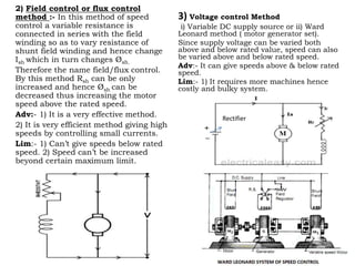
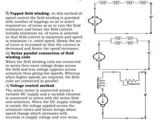
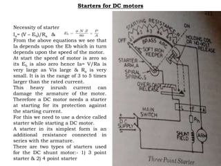
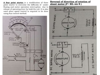
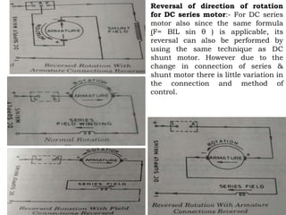
4) Speed can be controlled through methods like armature control using a rheostat, and field control using