1. Gas welding uses an exothermic reaction between oxygen and a combustible gas like acetylene or propane to generate heat for welding. Equipment consists of gas cylinders, pressure regulators, and a welding torch.
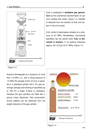
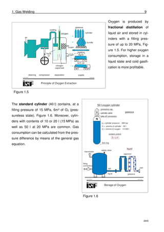
2. Acetylene is produced from calcium carbide and stored dissolved in acetone in porous cylinders. Oxygen is produced by fractional distillation of liquid air and stored in high pressure cylinders.
3. The welding torch mixes oxygen and the fuel gas to create a flame with different characteristics depending on the mixture ratio and outlet speed, affecting the weld properties. Leftward and rightward welding techniques are used depending on material thickness.
![1. Gas Welding 7
2005
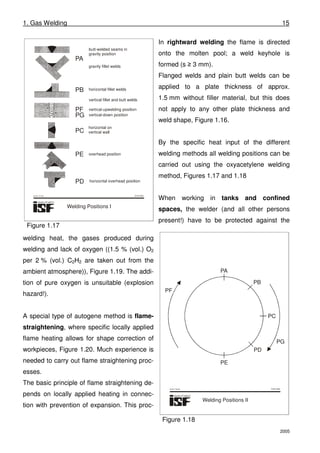
Although the oxy-acetylene process has been introduced long time ago it is still applied for its
flexibility and mobility. Equipment for oxyacetylene welding consists of just a few ele-
ments, the energy necessary for welding can be transported in cylinders, Figure 1.1.
Process energy is obtained from the exothermal chemical reaction between oxygen and a
combustible gas, Figure 1.2. Suitable combustible gases are C2H2, lighting gas, H2, C3H8 and
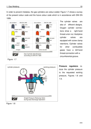
natural gas; here C3H8 has the highest calorific value. The highest flame intensity from point
of view of calorific value and flame propagation speed is, however, obtained with C2H2.
© ISF 2002
Equipment Components
for Gas Welding
acetylene hose
oxygen cylinder with pressure reducer
welding rod
oxygen hose
welding nozzle
welding torch
acetylene cylinder with pressure reducer
welding flame
workpiece
1
9
7
2
6
4
5
3
8
1
9
7
2
6
4
5
3
8
br-er1-01.cdr © ISF 2002
Properties of Fuel Gas in
Combination with Oxygen
2770
2850
3200
0
200
400
600
645
0
ignition temperature [ C]O
oxygen
air
0.5
1.0
1.5
2.0
2.5
0
density in normal state [kg/m ]3
propane
2.0
0.9
oxygen
1.43
acetylene
1.17
air
1.29
300
335
510
490
645
flame temperature with O2
flame efficiency with O2
flame velocity with O2
KW
/cm
2 cm
/s
43
10.3
8.5
1350
370
330
br-er1-02.cdr
naturalgas
propane
acetylene
naturalgasnaturalgas
propane
acetylene
°C
k
Figure 1.1 Figure 1.2
www.SeminarsTopics.com](https://image.slidesharecdn.com/05122013072956-gas-welding-done-140720074436-phpapp02/85/05122013072956-gas-welding-done-2-320.jpg)
![1. Gas Welding 14
2005
By changing the gas mixture outlet speed the flame can be adjusted to the heat requirements
of the welding job, for example when welding plates (thickness: 2 to 4 mm) with the welding
chamber size 3: “2 to 4 mm”, Figure 1.14. The gas mixture outlet speed is 100 to 130 m/s
when using a medium or normal flame, applied to at, for example, a 3 mm plate. Using a
soft flame, the gas outlet speed is lower (80 to 100 m/s) for the 2 mm plate, with a hard
flame it is higher (130 to 160 m/s) for the 4 mm plate.
Depending on the plate thickness are the working methods “leftward welding” and “rightward
welding” applied, Figure 1.15. A decisive factor for the designation of the working method is
the sequence of flame and welding rod as well as the manipulation of flame and welding rod.
The welding direction itself is of no importance. In leftward welding the flame is pointed at
the open gap and “wets” the molten pool; the heat input to the molten pool can be well con-
trolled by a slight movement of the torch (s ≤ 3 mm).
© ISF 2002
welding-rod flame welding bead
weld-rod flame
Rightward welding ist applied to a plate thickness of 3mm
upwards. The wire circles, the torch remains calm.
Advantages:
- the molten pool and the weld keyhole are easy to observe
- good root fusion
- the bath and the melting weld-rod are permanently protected
from the air
- narrow welding seam
- low gas consumption
Leftward welding is applied to a plate thickness of up to 3 mm.
The weld-rod dips into the molten pool from time to time,
but remains calm otherwise. The torch swings a little.
Advantages:
easy to handle on thin plates
Flame Welding
br-er1-15e.cdr
Figure 1.15
© ISF 2002
gap
preparations denotation sym-
bol
plate thickness
range s [mm]
from to
1,5
1,0
1,0 4,0
3,0 12,0
1,0 8,0
1,0 8,0
1,0 8,0
flange weld
plain butt
weld
V - weld
corner weld
lap seam
fillet weld
1 - 2
1 - 2
Gap Shapes for Gas Welding
s+1~~
r=
s
br-er1-16.cdr
Figure 1.16](https://image.slidesharecdn.com/05122013072956-gas-welding-done-140720074436-phpapp02/85/05122013072956-gas-welding-done-9-320.jpg)