Content
Process Concept
Process Scheduling
Operations on Processes
Interprocess Communication
Multithreaded Programming
Thread Scheduling
3.
Objectives
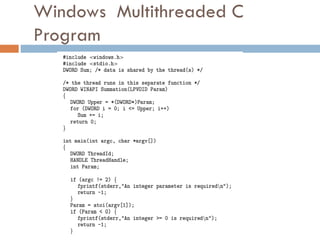
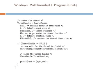
To introducethe notion of a process -- a
program in execution, which forms the basis of
all computation
To describe the various features of processes,
including scheduling, creation and termination,
and communication
To explore interprocess communication using
shared memory and message passing
To describe communication in client-server
systems
4.
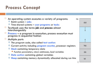
Process Concept
Anoperating system executes a variety of programs:
Batch system – jobs
Time-shared systems – user programs or tasks
Textbook uses the terms job and process almost
interchangeably
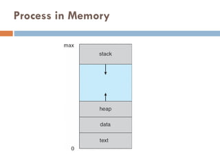
Process – a program in execution; process execution must
progress in sequential fashion
Multiple parts
The program code, also called text section
Current activity including program counter, processor registers
Stack containing temporary data
Function parameters, return addresses, local variables
Data section containing global variables
Heap containing memory dynamically allocated during run time
5.
Process Concept (Cont.)
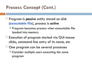
Program is passive entity stored on disk
(executable file), process is active
Program becomes process when executable file
loaded into memory
Execution of program started via GUI mouse
clicks, command line entry of its name, etc
One program can be several processes
Consider multiple users executing the same
program
Process State
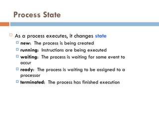
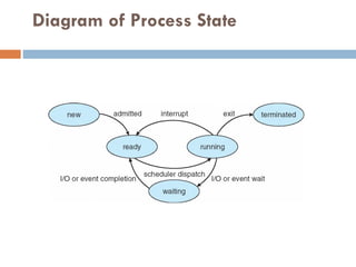
Asa process executes, it changes state
new: The process is being created
running: Instructions are being executed
waiting: The process is waiting for some event to
occur
ready: The process is waiting to be assigned to a
processor
terminated: The process has finished execution
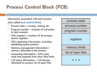
Process Control Block(PCB)
Information associated with each process
(also called task control block)
Process state – running, waiting, etc
Program counter – location of instruction
to next execute
CPU registers – contents of all process-
centric registers
CPU scheduling information- priorities,
scheduling queue pointers
Memory-management information –
memory allocated to the process
Accounting information – CPU used,
clock time elapsed since start, time limits
I/O status information – I/O devices
allocated to process, list of open files
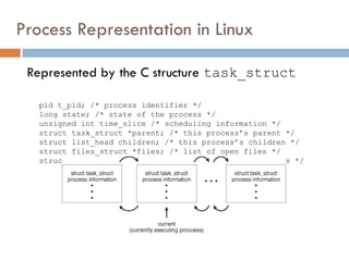
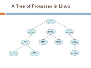
Process Representation inLinux
Represented by the C structure task_struct
pid t_pid; /* process identifier */
long state; /* state of the process */
unsigned int time_slice /* scheduling information */
struct task_struct *parent; /* this process’s parent */
struct list_head children; /* this process’s children */
struct files_struct *files; /* list of open files */
struct mm_struct *mm; /* address space of this process */
12.
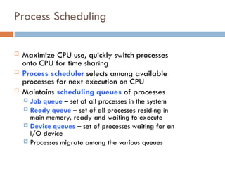
Process Scheduling
MaximizeCPU use, quickly switch processes
onto CPU for time sharing
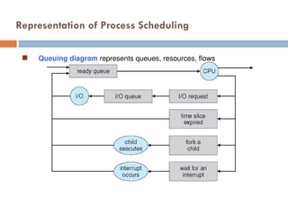
Process scheduler selects among available
processes for next execution on CPU
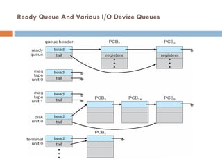
Maintains scheduling queues of processes
Job queue – set of all processes in the system
Ready queue – set of all processes residing in
main memory, ready and waiting to execute
Device queues – set of processes waiting for an
I/O device
Processes migrate among the various queues
Schedulers
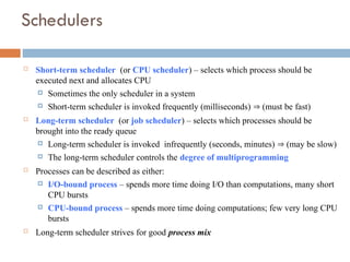
Short-term scheduler(or CPU scheduler) – selects which process should be
executed next and allocates CPU
Sometimes the only scheduler in a system
Short-term scheduler is invoked frequently (milliseconds) (must be fast)
Long-term scheduler (or job scheduler) – selects which processes should be
brought into the ready queue
Long-term scheduler is invoked infrequently (seconds, minutes) (may be slow)
The long-term scheduler controls the degree of multiprogramming
Processes can be described as either:
I/O-bound process – spends more time doing I/O than computations, many short
CPU bursts
CPU-bound process – spends more time doing computations; few very long CPU
bursts
Long-term scheduler strives for good process mix
16.
Addition of MediumTerm Scheduling
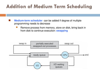
Medium-term scheduler can be added if degree of multiple
programming needs to decrease
Remove process from memory, store on disk, bring back in
from disk to continue execution: swapping
17.
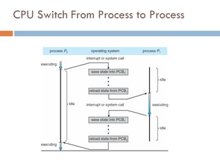
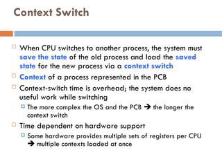
Context Switch
WhenCPU switches to another process, the system must
save the state of the old process and load the saved
state for the new process via a context switch
Context of a process represented in the PCB
Context-switch time is overhead; the system does no
useful work while switching
The more complex the OS and the PCB the longer the
context switch
Time dependent on hardware support
Some hardware provides multiple sets of registers per CPU
multiple contexts loaded at once
18.
Operations on Processes
System must provide mechanisms for:
process creation,
process termination,
and so on as detailed next
19.
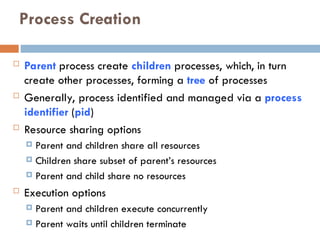
Process Creation
Parentprocess create children processes, which, in turn
create other processes, forming a tree of processes
Generally, process identified and managed via a process
identifier (pid)
Resource sharing options
Parent and children share all resources
Children share subset of parent’s resources
Parent and child share no resources
Execution options
Parent and children execute concurrently
Parent waits until children terminate
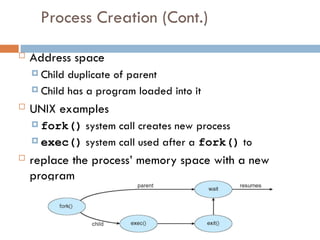
Process Creation (Cont.)
Address space
Child duplicate of parent
Child has a program loaded into it
UNIX examples
fork() system call creates new process
exec() system call used after a fork() to
replace the process’ memory space with a new
program
22.
Process Termination
Processexecutes last statement and then asks the
operating system to delete it using the exit() system
call.
Returns status data from child to parent (via wait())
Process’ resources are deallocated by operating system
Parent may terminate the execution of children processes
using the abort() system call. Some reasons for doing
so:
Child has exceeded allocated resources
Task assigned to child is no longer required
The parent is exiting and the operating systems does not allow
a child to continue if its parent terminates
23.
Process Termination
Someoperating systems do not allow child to exists if its parent has
terminated. If a process terminates, then all its children must also be
terminated.
cascading termination. All children, grandchildren, etc. are terminated.
The termination is initiated by the operating system.
The parent process may wait for termination of a child process by using
the wait()system call. The call returns status information and the pid
of the terminated process
pid = wait(&status);
If no parent waiting (did not invoke wait()) process is a zombie
If parent terminated without invoking wait , process is an orphan
24.
Interprocess Communication –Message
Passing
Mechanism for processes to communicate and to
synchronize their actions
Message system – processes communicate with each
other without resorting to shared variables
IPC facility provides two operations:
send(message)
receive(message)
The message size is either fixed or variable
25.
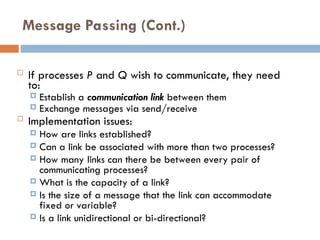
Message Passing (Cont.)
If processes P and Q wish to communicate, they need
to:
Establish a communication link between them
Exchange messages via send/receive
Implementation issues:
How are links established?
Can a link be associated with more than two processes?
How many links can there be between every pair of
communicating processes?
What is the capacity of a link?
Is the size of a message that the link can accommodate
fixed or variable?
Is a link unidirectional or bi-directional?
26.
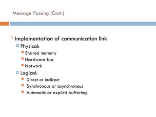
Message Passing (Cont.)
Implementation of communication link
Physical:
Shared memory
Hardware bus
Network
Logical:
Direct or indirect
Synchronous or asynchronous
Automatic or explicit buffering
27.
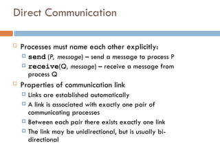
Direct Communication
Processesmust name each other explicitly:
send (P, message) – send a message to process P
receive(Q, message) – receive a message from
process Q
Properties of communication link
Links are established automatically
A link is associated with exactly one pair of
communicating processes
Between each pair there exists exactly one link
The link may be unidirectional, but is usually bi-
directional
28.
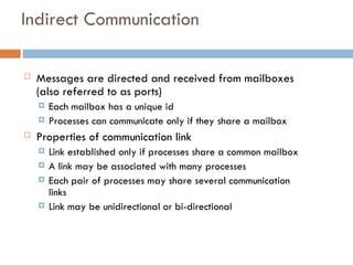
Indirect Communication
Messagesare directed and received from mailboxes
(also referred to as ports)
Each mailbox has a unique id
Processes can communicate only if they share a mailbox
Properties of communication link
Link established only if processes share a common mailbox
A link may be associated with many processes
Each pair of processes may share several communication
links
Link may be unidirectional or bi-directional
29.
Indirect Communication
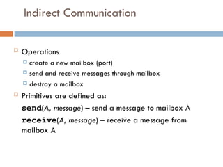
Operations
create a new mailbox (port)
send and receive messages through mailbox
destroy a mailbox
Primitives are defined as:
send(A, message) – send a message to mailbox A
receive(A, message) – receive a message from
mailbox A
30.
Indirect Communication
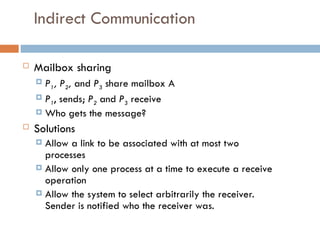
Mailboxsharing
P1, P2, and P3 share mailbox A
P1, sends; P2 and P3 receive
Who gets the message?
Solutions
Allow a link to be associated with at most two
processes
Allow only one process at a time to execute a receive
operation
Allow the system to select arbitrarily the receiver.
Sender is notified who the receiver was.
31.
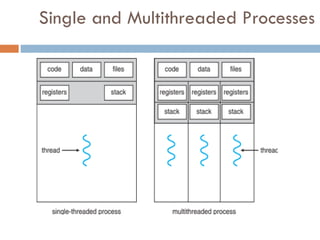
Threads
So far,process has a single thread of
execution
Consider having multiple program counters
per process
Multiple locations can execute at once
Multiple threads of control -> threads
Must then have storage for thread details,
multiple program counters in PCB
See next chapter
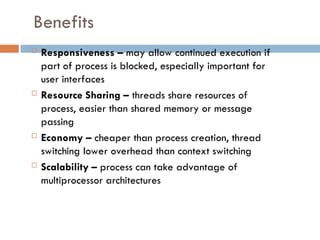
Benefits
Responsiveness –may allow continued execution if
part of process is blocked, especially important for
user interfaces
Resource Sharing – threads share resources of
process, easier than shared memory or message
passing
Economy – cheaper than process creation, thread
switching lower overhead than context switching
Scalability – process can take advantage of
multiprocessor architectures
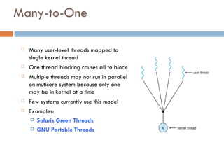
Many-to-One
Many user-levelthreads mapped to
single kernel thread
One thread blocking causes all to block
Multiple threads may not run in parallel
on muticore system because only one
may be in kernel at a time
Few systems currently use this model
Examples:
Solaris Green Threads
GNU Portable Threads
37.
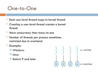
One-to-One
Each user-levelthread maps to kernel thread
Creating a user-level thread creates a kernel
thread
More concurrency than many-to-one
Number of threads per process sometimes
restricted due to overhead
Examples
Windows
Linux
Solaris 9 and later
38.
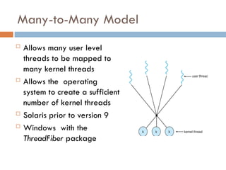
Many-to-Many Model
Allowsmany user level
threads to be mapped to
many kernel threads
Allows the operating
system to create a sufficient
number of kernel threads
Solaris prior to version 9
Windows with the
ThreadFiber package
39.
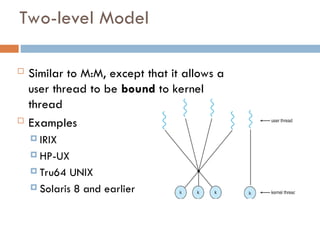
Two-level Model
Similarto M:M, except that it allows a
user thread to be bound to kernel
thread
Examples
IRIX
HP-UX
Tru64 UNIX
Solaris 8 and earlier
40.
Thread Libraries
Threadlibrary provides programmer
with API for creating and managing
threads
Two primary ways of implementing
Library entirely in user space
Kernel-level library supported by the OS
41.
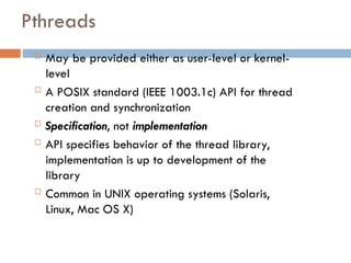
Pthreads
May beprovided either as user-level or kernel-
level
A POSIX standard (IEEE 1003.1c) API for thread
creation and synchronization
Specification, not implementation
API specifies behavior of the thread library,
implementation is up to development of the
library
Common in UNIX operating systems (Solaris,
Linux, Mac OS X)
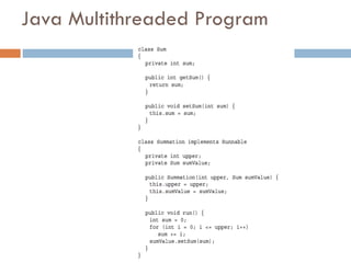
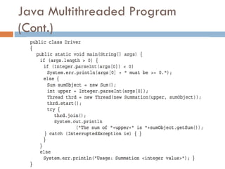
Java Threads
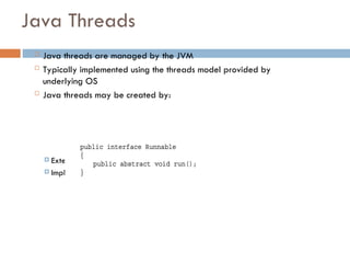
Javathreads are managed by the JVM
Typically implemented using the threads model provided by
underlying OS
Java threads may be created by:
Extending Thread class
Implementing the Runnable interface
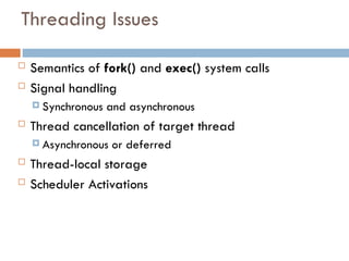
Threading Issues
Semanticsof fork() and exec() system calls
Signal handling
Synchronous and asynchronous
Thread cancellation of target thread
Asynchronous or deferred
Thread-local storage
Scheduler Activations
51.
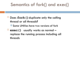
Semantics of fork()and exec()
Does fork()duplicate only the calling
thread or all threads?
Some UNIXes have two versions of fork
exec() usually works as normal –
replace the running process including all
threads
52.
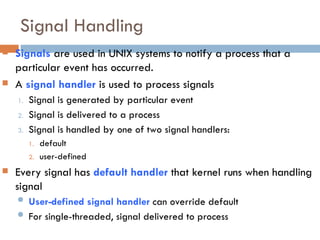
Signal Handling
Signalsare used in UNIX systems to notify a process that a
particular event has occurred.
A signal handler is used to process signals
1. Signal is generated by particular event
2. Signal is delivered to a process
3. Signal is handled by one of two signal handlers:
1. default
2. user-defined
Every signal has default handler that kernel runs when handling
signal
User-defined signal handler can override default
For single-threaded, signal delivered to process
53.
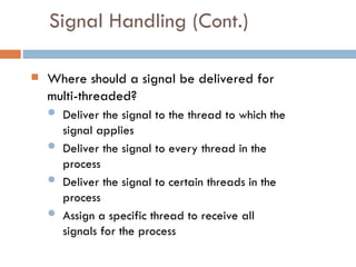
Signal Handling (Cont.)
Where should a signal be delivered for
multi-threaded?
Deliver the signal to the thread to which the
signal applies
Deliver the signal to every thread in the
process
Deliver the signal to certain threads in the
process
Assign a specific thread to receive all
signals for the process
54.
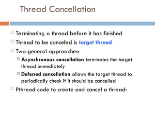
Thread Cancellation
Terminatinga thread before it has finished
Thread to be canceled is target thread
Two general approaches:
Asynchronous cancellation terminates the target
thread immediately
Deferred cancellation allows the target thread to
periodically check if it should be cancelled
Pthread code to create and cancel a thread:
55.
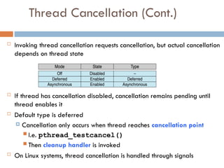
Thread Cancellation (Cont.)
Invoking thread cancellation requests cancellation, but actual cancellation
depends on thread state
If thread has cancellation disabled, cancellation remains pending until
thread enables it
Default type is deferred
Cancellation only occurs when thread reaches cancellation point
I.e. pthread_testcancel()
Then cleanup handler is invoked
On Linux systems, thread cancellation is handled through signals
56.
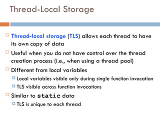
Thread-Local Storage
Thread-localstorage (TLS) allows each thread to have
its own copy of data
Useful when you do not have control over the thread
creation process (i.e., when using a thread pool)
Different from local variables
Local variables visible only during single function invocation
TLS visible across function invocations
Similar to static data
TLS is unique to each thread
57.
Scheduler Activations
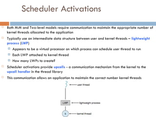
BothM:M and Two-level models require communication to maintain the appropriate number of
kernel threads allocated to the application
Typically use an intermediate data structure between user and kernel threads – lightweight
process (LWP)
Appears to be a virtual processor on which process can schedule user thread to run
Each LWP attached to kernel thread
How many LWPs to create?
Scheduler activations provide upcalls - a communication mechanism from the kernel to the
upcall handler in the thread library
This communication allows an application to maintain the correct number kernel threads
58.
Basic Concepts
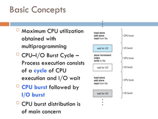
MaximumCPU utilization
obtained with
multiprogramming
CPU–I/O Burst Cycle –
Process execution consists
of a cycle of CPU
execution and I/O wait
CPU burst followed by
I/O burst
CPU burst distribution is
of main concern
59.
CPU Scheduler
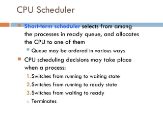
Short-termscheduler selects from among
the processes in ready queue, and allocates
the CPU to one of them
Queue may be ordered in various ways
CPU scheduling decisions may take place
when a process:
1.Switches from running to waiting state
2.Switches from running to ready state
3.Switches from waiting to ready
4. Terminates
60.
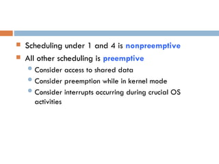
Scheduling under1 and 4 is nonpreemptive
All other scheduling is preemptive
Consider access to shared data
Consider preemption while in kernel mode
Consider interrupts occurring during crucial OS
activities
61.
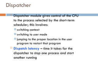
Dispatcher
Dispatcher modulegives control of the CPU
to the process selected by the short-term
scheduler; this involves:
switching context
switching to user mode
jumping to the proper location in the user
program to restart that program
Dispatch latency – time it takes for the
dispatcher to stop one process and start
another running
62.
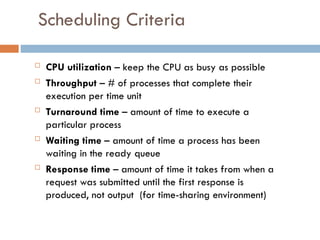
Scheduling Criteria
CPUutilization – keep the CPU as busy as possible
Throughput – # of processes that complete their
execution per time unit
Turnaround time – amount of time to execute a
particular process
Waiting time – amount of time a process has been
waiting in the ready queue
Response time – amount of time it takes from when a
request was submitted until the first response is
produced, not output (for time-sharing environment)
63.
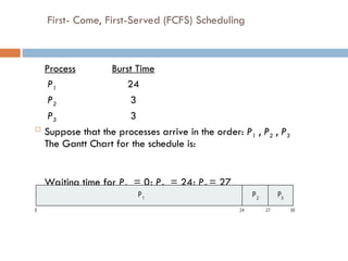
First- Come, First-Served(FCFS) Scheduling
Process Burst Time
P1 24
P2 3
P3 3
Suppose that the processes arrive in the order: P1 , P2 , P3
The Gantt Chart for the schedule is:
Waiting time for P1 = 0; P2 = 24; P3 = 27
Average waiting time: (0 + 24 + 27)/3 = 17
P P P
1 2 3
0 24 30
27
64.
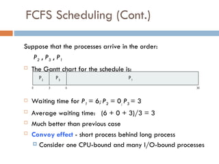
FCFS Scheduling (Cont.)
Supposethat the processes arrive in the order:
P2 , P3 , P1
The Gantt chart for the schedule is:
Waiting time for P1 = 6; P2 = 0; P3 = 3
Average waiting time: (6 + 0 + 3)/3 = 3
Much better than previous case
Convoy effect - short process behind long process
Consider one CPU-bound and many I/O-bound processes
P1
0 3 6 30
P2
P3
65.
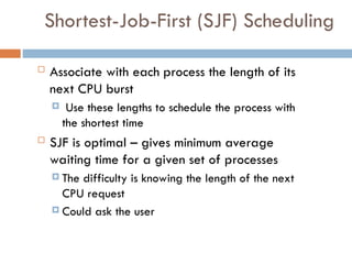
Shortest-Job-First (SJF) Scheduling
Associate with each process the length of its
next CPU burst
Use these lengths to schedule the process with
the shortest time
SJF is optimal – gives minimum average
waiting time for a given set of processes
The difficulty is knowing the length of the next
CPU request
Could ask the user
66.
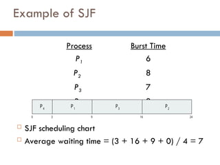
Example of SJF
ProcessArrivaBurst Time
P1 0.0 6
P2 2.0 8
P3 4.0 7
P4 5.0 3
SJF scheduling chart
Average waiting time = (3 + 16 + 9 + 0) / 4 = 7
P3
0 3 24
P4
P1
16
9
P2
67.
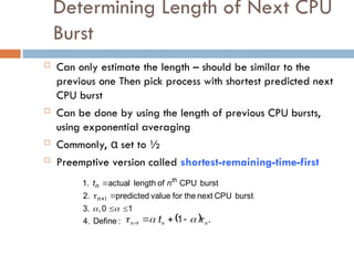
Determining Length ofNext CPU
Burst
Can only estimate the length – should be similar to the
previous one Then pick process with shortest predicted next
CPU burst
Can be done by using the length of previous CPU bursts,
using exponential averaging
Commonly, α set to ½
Preemptive version called shortest-remaining-time-first
:
Define
4.
1
0
,
3.
burst
CPU
next
the
for
value
predicted
2.
burst
CPU
of
length
actual
1.
1
n
th
n n
t
.
1
1 n
n
n t
68.
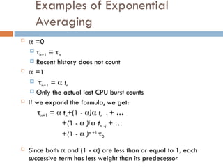
Examples of Exponential
Averaging
=0
n+1 = n
Recent history does not count
=1
n+1 = tn
Only the actual last CPU burst counts
If we expand the formula, we get:
n+1 = tn+(1 - ) tn -1 + …
+(1 - )j
tn -j + …
+(1 - )n +1
0
Since both and (1 - ) are less than or equal to 1, each
successive term has less weight than its predecessor
69.
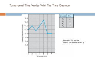
Example of Shortest-remaining-time-first
Now we add the concepts of varying arrival times and preemption
to the analysis
ProcessAarri Arrival TimeTBurst Time
P1 0 8
P2 1 4
P3 2 9
P4 3 5
Preemptive SJF Gantt Chart
Average waiting time = [(10-1)+(1-1)+(17-2)+5-3)]/4 = 26/4 =
6.5 msec
P4
0 1 26
P1
P2
10
P3
P1
5 17
70.
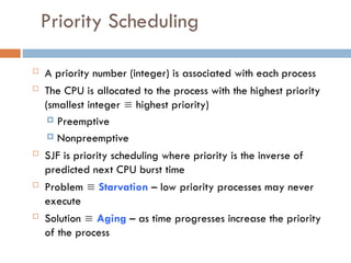
Priority Scheduling
Apriority number (integer) is associated with each process
The CPU is allocated to the process with the highest priority
(smallest integer highest priority)
Preemptive
Nonpreemptive
SJF is priority scheduling where priority is the inverse of
predicted next CPU burst time
Problem Starvation – low priority processes may never
execute
Solution Aging – as time progresses increase the priority
of the process
71.
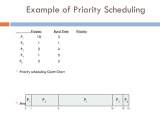
Example of PriorityScheduling
ProcessA arri Burst TimeT Priority
P1 10 3
P2 1 1
P3 2 4
P4 1 5
P5 5 2
Priority scheduling Gantt Chart
Average waiting time = 8.2 msec 1
0 1 19
P1
P2
16
P4
P3
6 18
P
72.
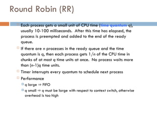
Round Robin (RR)
Each process gets a small unit of CPU time (time quantum q),
usually 10-100 milliseconds. After this time has elapsed, the
process is preempted and added to the end of the ready
queue.
If there are n processes in the ready queue and the time
quantum is q, then each process gets 1/n of the CPU time in
chunks of at most q time units at once. No process waits more
than (n-1)q time units.
Timer interrupts every quantum to schedule next process
Performance
q large FIFO
q small q must be large with respect to context switch, otherwise
overhead is too high
73.
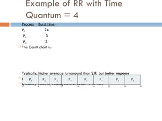
Example of RRwith Time
Quantum = 4
Process Burst Time
P1 24
P2 3
P3 3
The Gantt chart is:
Typically, higher average turnaround than SJF, but better response
q should be large compared to context switch time
q usually 10ms to 100ms, context switch < 10 usec
P P P
1 1 1
0 18 30
26
14
4 7 10 22
P2
P3
P1
P1
P1
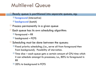
Multilevel Queue
Readyqueue is partitioned into separate queues, eg:
foreground (interactive)
background (batch)
Process permanently in a given queue
Each queue has its own scheduling algorithm:
foreground – RR
background – FCFS
Scheduling must be done between the queues:
Fixed priority scheduling; (i.e., serve all from foreground then
from background). Possibility of starvation.
Time slice – each queue gets a certain amount of CPU time which
it can schedule amongst its processes; i.e., 80% to foreground in
RR
20% to background in FCFS
76.
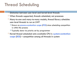
Thread Scheduling
Distinctionbetween user-level and kernel-level threads
When threads supported, threads scheduled, not processes
Many-to-one and many-to-many models, thread library schedules
user-level threads to run on LWP
Known as process-contention scope (PCS) since scheduling competition
is within the process
Typically done via priority set by programmer
Kernel thread scheduled onto available CPU is system-contention
scope (SCS) – competition among all threads in system
#13 Maintains scheduling queues of processes
Job queue – set of all processes in the system
Ready queue – set of all processes residing in main memory, ready and waiting to execute
Device queues – set of processes waiting for an I/O device
Processes migrate among the various queues

![Example of Shortest-remaining-time-first
Now we add the concepts of varying arrival times and preemption
to the analysis
ProcessAarri Arrival TimeTBurst Time
P1 0 8
P2 1 4
P3 2 9
P4 3 5
Preemptive SJF Gantt Chart
Average waiting time = [(10-1)+(1-1)+(17-2)+5-3)]/4 = 26/4 =
6.5 msec
P4
0 1 26
P1
P2
10
P3
P1
5 17](https://image.slidesharecdn.com/02-osprocess-251006094300-d316b148/85/02-Operating-System-Process-state-synchronization-69-320.jpg)