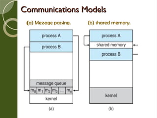
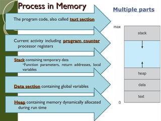
This presentation provides an overview of key concepts in process management within operating systems. It explains the process concept, CPU scheduling, operations on processes (creation, termination, and hierarchy), and interprocess communication (IPC) mechanisms. Ideal for students and learners exploring core OS concepts such as process states, scheduling algorithms, and communication models.


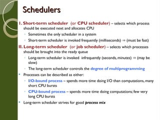

![Bounded-Buffer – Shared-Memory Solution
Bounded-Buffer – Shared-Memory Solution
Shared data
#define BUFFER_SIZE 10
typedef struct {
. . .
} item;
item buffer[BUFFER_SIZE];
int in = 0;
int out = 0;](https://image.slidesharecdn.com/osunitiichap3-251014152334-b03d0891/85/Process-and-CPU-Scheduling-algorithms-and-IPC-33-320.jpg)
![Bounded-Buffer
Bounded-Buffer
item next_produced;
while (true) {
/* produce an item in
next produced */
while (((in + 1) %
BUFFER_SIZE) == out);
/* do nothing */
buffer[in] =
next_produced;
in = (in + 1) %
BUFFER_SIZE;
}
item next_consumed;
while (true) {
while (in == out);
/* do nothing */
next_consumed =
buffer[out];
out = (out + 1) %
BUFFER_SIZE;
/* consume the item in
next consumed */
}
Producer Consumer
This scheme allows at most BUFFER_SIZE -1 items
in the buffer at the same time.](https://image.slidesharecdn.com/osunitiichap3-251014152334-b03d0891/85/Process-and-CPU-Scheduling-algorithms-and-IPC-34-320.jpg)