Download to read offline


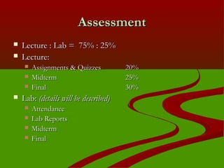


This course covers the fundamentals of digital logic design including binary numbers, digital circuits, combinational and sequential logic circuits. It will be taught through lectures on Thursdays from 8:30-10:15AM in room 1239 of the Science Building and labs on Wednesdays from 12:05-2:45PM in room 1227. Student assessment will consist of assignments, quizzes, a midterm, and final exam for the lecture portion and lab attendance, reports, and exams for the lab portion. Relevant course materials will be provided on the instructor's webpage.


![Experimentdsd[1]](https://cdn.slidesharecdn.com/ss_thumbnails/experimentdsd1-121006103055-phpapp01-thumbnail.jpg?width=640&height=640&fit=bounds)