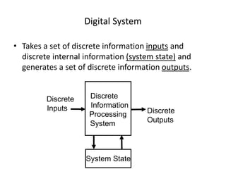
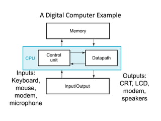
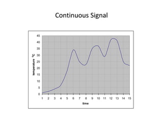
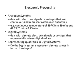
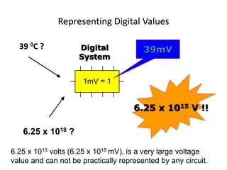
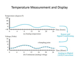
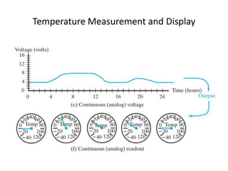
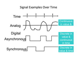
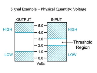
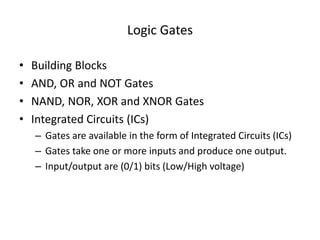
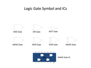
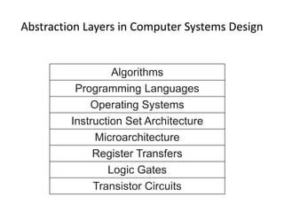
Digital Logic & Design
Lecture 01
Grading
• Midterm 25%
• Finalterm 50%
• Sessional: 25%
– Quizzes (5%)
– Assignments (10%)
– Project (10%)
Text Book
• Logic and Computer Design Fundamentals, 5th
Edition 2015 M. Morris Mano, Charles R Kime.
Digital System
• Takes a set of discrete information inputs and
discrete internal information (system state) and
generates a set of discrete information outputs.
System State
Discrete
Information
Processing
System
Discrete
Inputs Discrete
Outputs
A Digital Computer Example
Inputs:
Keyboard,
mouse,
modem,
microphone
Outputs:
CRT, LCD,
modem,
speakers
Memory
Control
unit Datapath
Input/Output
CPU
Analogue Quantities
Continuous Quantity
• Intensity of Light
• Temperature
• Velocity
The rise of continuous not discrete.
Digital Values
Discrete set of values
• Digital values on the other hand are a discrete
set of values which represent the actual
Continuous Signal
• Consider the continuous signal shown in the
diagram
Continuous Signal
0
5
10
15
20
25
30
35
40
45
1 2 3 4 5 6 7 8 9 10 11 12 13 14 15
time
temperature
0
C
Digital Values
• The continuous signal can be represented
digitally by taking samples at regular but fixed
intervals
• In this case 15 samples at regular time intervals
are collected
• The digital representation of the continuous
signal only approximates the original signal and
does not truly represent the original signal as can
be seen by plotting the digital values
Continuous Signal
1 2
4
7
34
25
23
37
29
42 41
25
22
18
35
0
5
10
15
20
25
30
35
40
45
1 2 3 4 5 6 7 8 9 10 11 12 13 14 15
time
temperature
0
C
Digital Representation
1 2
4
7
18
34
25
23
35
37
29
42 41
25
22
0
5
10
15
20
25
30
35
40
45
1 2 3 4 5 6 7 8 9 10 11 12 13 14 15
samples
temperature
0
C
The reconstructed continuous signal does not give an
exact replica of the original.
Under Sampling
0
5
10
15
20
25
30
35
40
45
1 3 5 7 9 11 13 15
samples
temperature
0
C
If the number of samples are collected at every odd interval
of time
Electronic Processing
• Analogue Systems
– deal with electronic signals or voltages that are
continuous and represent continuous quantities
– e.g. continuous temperature of 39 0C into 39 mVs and
42.75 0C into 42.75 mVs.
• Digital Systems
– deal with discrete electronic signals or voltages that
represent discrete or digital values
• Representing quantities in Digital Systems
– Do the Digital systems represent discrete values in
terms of voltages?
Representing Digital Values
39 0C ?
a1
1
a2
2
3
a3
4
a4
b1
b2
b3
b4
5
6
7
8
Vcc1
0
GND
0
1mV = 1
39mV
6.25 x 10¹⁵ V !!
Digital
System
6.25 x 10¹⁸ ?
6.25 x 10¹⁵ volts (6.25 x 10¹⁸ mV), is a very large voltage
value and can not be practically represented by any circuit.
Temperature Measurement and Display
Digital Systems
• Two Voltage Levels
– The two voltage levels represent two states
– A voltage level of 5v represents logic high or logic 1 state
and a voltage level of 0v represents logic low or logic 0
state.
• Two States
– On/Off
– Black/White
– Hot/Cold
– Stationary/Moving
Signal
• An information variable represented by physical quantity.
• For digital systems, the variable takes on discrete values.
• Two level, or binary values are the most prevalent values in
digital systems.
• Binary values are represented abstractly by:
– digits 0 and 1
– words (symbols) False (F) and True (T)
– words (symbols) Low (L) and High (H)
– and words On and Off.
• Binary values are represented by values or ranges of values of
physical quantities
Signal Examples Over Time
Analog
Asynchronous
Synchronous
Time
Continuous
in value &
time
Discrete in
value &
continuous
in time
Discrete in
value & time
Digital
Signal Example – Physical Quantity: Voltage
5.0
4.0
3.0
2.0
1.0
0.0
Volts
HIGH
LOW
HIGH
LOW
OUTPUT INPUT
Threshold
Region
Binary Number System
• Binary Numbers
– Allows only two numbers 0 and 1
– The Binary digit is called a bit
• Representing Multiple Values
– A combination of binary bits is used
– 2 bits allow 4 different values to be represented
– A temp of 39 is represented by a combination of six bits
100111
• Combination of 0v & 5v
– The number 39 is represented in a digital system by a
combination of voltage levels 5, 0, 0, 5, 5 and 5 volts
Merits of Digital Systems
• Efficient Processing & Data Storage
• Efficient & Reliable Transmission
• Detection and Correction of Errors
• Precise & Accurate Reproduction
• Easy Design and Implementation
• Occupy minimum space
Information Processing
• Numbers
– perform arithmetic operations on the numbers
• Text
– perform editing operations on text
• Formula and Equations
– mathematical and scientific formulas
• Drawings and Pictures
• Sound and Music
• All this diverse types of information is represented in
the form of binary numbers
Logic Gates
• Building Blocks
• AND, OR and NOT Gates
• NAND, NOR, XOR and XNOR Gates
• Integrated Circuits (ICs)
– Gates are available in the form of Integrated Circuits (ICs)
– Gates take one or more inputs and produce one output.
– Input/output are (0/1) bits (Low/High voltage)
Logic Gate Symbol and ICs
AND Gate OR Gate NOT Gate
NAND Gate
1
2
3
4
5
6
GND
Vcc
13
12
11
10
9
8
7400
NOR Gate XOR Gate XNOR Gate
NAND Gate IC
Combinational Circuits
• Combination of Logic Gates
• Adder Combinational Circuit
Adder Combinational Circuit
Sum
Carry
Functional Devices
• Commonly used functional ICs are
– Adders
– Comparators
– Encoders/Decoders
– Multiplexers/Demultiplexers
Abstraction Layers in Computer Systems Design
Algorithms
Programming Languages
Operating Systems
Instruction Set Architecture
Microarchitecture
Register Transfers
Logic Gates
Transistor Circuits
Summary
• Continuous Signals
• Digital Representation in Binary
• Information Processing
• Logic Gates

- DLD_Lecture_01.ppt

  • 1.
    Digital Logic &Design Lecture 01
  • 2.
    Grading • Midterm 25% •Finalterm 50% • Sessional: 25% – Quizzes (5%) – Assignments (10%) – Project (10%)
  • 3.
    Text Book • Logicand Computer Design Fundamentals, 5th Edition 2015 M. Morris Mano, Charles R Kime.
  • 4.
    Digital System • Takesa set of discrete information inputs and discrete internal information (system state) and generates a set of discrete information outputs. System State Discrete Information Processing System Discrete Inputs Discrete Outputs
  • 5.
    A Digital ComputerExample Inputs: Keyboard, mouse, modem, microphone Outputs: CRT, LCD, modem, speakers Memory Control unit Datapath Input/Output CPU
  • 6.
    Analogue Quantities Continuous Quantity •Intensity of Light • Temperature • Velocity The rise of continuous not discrete.
  • 7.
    Digital Values Discrete setof values • Digital values on the other hand are a discrete set of values which represent the actual Continuous Signal • Consider the continuous signal shown in the diagram
  • 8.
    Continuous Signal 0 5 10 15 20 25 30 35 40 45 1 23 4 5 6 7 8 9 10 11 12 13 14 15 time temperature 0 C
  • 9.
    Digital Values • Thecontinuous signal can be represented digitally by taking samples at regular but fixed intervals • In this case 15 samples at regular time intervals are collected • The digital representation of the continuous signal only approximates the original signal and does not truly represent the original signal as can be seen by plotting the digital values
  • 10.
    Continuous Signal 1 2 4 7 34 25 23 37 29 4241 25 22 18 35 0 5 10 15 20 25 30 35 40 45 1 2 3 4 5 6 7 8 9 10 11 12 13 14 15 time temperature 0 C
  • 11.
    Digital Representation 1 2 4 7 18 34 25 23 35 37 29 4241 25 22 0 5 10 15 20 25 30 35 40 45 1 2 3 4 5 6 7 8 9 10 11 12 13 14 15 samples temperature 0 C The reconstructed continuous signal does not give an exact replica of the original.
  • 12.
    Under Sampling 0 5 10 15 20 25 30 35 40 45 1 35 7 9 11 13 15 samples temperature 0 C If the number of samples are collected at every odd interval of time
  • 13.
    Electronic Processing • AnalogueSystems – deal with electronic signals or voltages that are continuous and represent continuous quantities – e.g. continuous temperature of 39 0C into 39 mVs and 42.75 0C into 42.75 mVs. • Digital Systems – deal with discrete electronic signals or voltages that represent discrete or digital values • Representing quantities in Digital Systems – Do the Digital systems represent discrete values in terms of voltages?
  • 14.
    Representing Digital Values 390C ? a1 1 a2 2 3 a3 4 a4 b1 b2 b3 b4 5 6 7 8 Vcc1 0 GND 0 1mV = 1 39mV 6.25 x 10¹⁵ V !! Digital System 6.25 x 10¹⁸ ? 6.25 x 10¹⁵ volts (6.25 x 10¹⁸ mV), is a very large voltage value and can not be practically represented by any circuit.
  • 15.
  • 16.
  • 17.
  • 18.
    Digital Systems • TwoVoltage Levels – The two voltage levels represent two states – A voltage level of 5v represents logic high or logic 1 state and a voltage level of 0v represents logic low or logic 0 state. • Two States – On/Off – Black/White – Hot/Cold – Stationary/Moving
  • 19.
    Signal • An informationvariable represented by physical quantity. • For digital systems, the variable takes on discrete values. • Two level, or binary values are the most prevalent values in digital systems. • Binary values are represented abstractly by: – digits 0 and 1 – words (symbols) False (F) and True (T) – words (symbols) Low (L) and High (H) – and words On and Off. • Binary values are represented by values or ranges of values of physical quantities
  • 20.
    Signal Examples OverTime Analog Asynchronous Synchronous Time Continuous in value & time Discrete in value & continuous in time Discrete in value & time Digital
  • 21.
    Signal Example –Physical Quantity: Voltage 5.0 4.0 3.0 2.0 1.0 0.0 Volts HIGH LOW HIGH LOW OUTPUT INPUT Threshold Region
  • 22.
    Binary Number System •Binary Numbers – Allows only two numbers 0 and 1 – The Binary digit is called a bit • Representing Multiple Values – A combination of binary bits is used – 2 bits allow 4 different values to be represented – A temp of 39 is represented by a combination of six bits 100111 • Combination of 0v & 5v – The number 39 is represented in a digital system by a combination of voltage levels 5, 0, 0, 5, 5 and 5 volts
  • 23.
    Merits of DigitalSystems • Efficient Processing & Data Storage • Efficient & Reliable Transmission • Detection and Correction of Errors • Precise & Accurate Reproduction • Easy Design and Implementation • Occupy minimum space
  • 24.
    Information Processing • Numbers –perform arithmetic operations on the numbers • Text – perform editing operations on text • Formula and Equations – mathematical and scientific formulas • Drawings and Pictures • Sound and Music • All this diverse types of information is represented in the form of binary numbers
  • 25.
    Logic Gates • BuildingBlocks • AND, OR and NOT Gates • NAND, NOR, XOR and XNOR Gates • Integrated Circuits (ICs) – Gates are available in the form of Integrated Circuits (ICs) – Gates take one or more inputs and produce one output. – Input/output are (0/1) bits (Low/High voltage)
  • 26.
    Logic Gate Symboland ICs AND Gate OR Gate NOT Gate NAND Gate 1 2 3 4 5 6 GND Vcc 13 12 11 10 9 8 7400 NOR Gate XOR Gate XNOR Gate NAND Gate IC
  • 27.
    Combinational Circuits • Combinationof Logic Gates • Adder Combinational Circuit
  • 28.
  • 29.
    Functional Devices • Commonlyused functional ICs are – Adders – Comparators – Encoders/Decoders – Multiplexers/Demultiplexers
  • 30.
    Abstraction Layers inComputer Systems Design Algorithms Programming Languages Operating Systems Instruction Set Architecture Microarchitecture Register Transfers Logic Gates Transistor Circuits
  • 31.
    Summary • Continuous Signals •Digital Representation in Binary • Information Processing • Logic Gates