The document provides an overview of digital logic design, emphasizing the differences between digital and analog systems, basic digital logic functions, and characteristics of digital waveforms. It covers essential concepts such as binary representation, timing parameters, the use of integrated circuits, and the functionality of logic gates. Additionally, it discusses the applications of digital electronics in various fields and the measurement and troubleshooting of digital circuits.


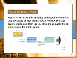
![EE-227 Digital Logic Design
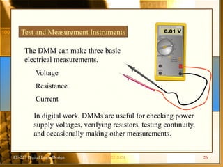
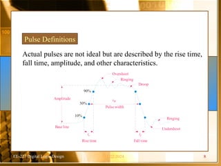
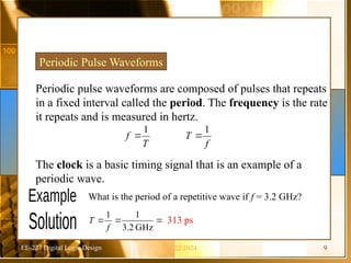
Pulse Definitions
In addition to frequency and period, repetitive pulse waveforms
are described by the amplitude (A), pulse width (tW) and duty
cycle. Duty cycle is the ratio of tW to T.
Volts
Time
Amplitude (A)
Pulse
width
(tW)
Period, T
11/22/2024 10[E-1]](https://image.slidesharecdn.com/ch1intro-241122170242-675df225/85/Ch1-Intr-for-the-distributed-system-and-clock-10-320.jpg)
![EE-227 Digital Logic Design
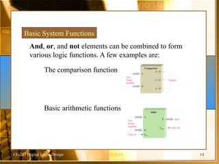
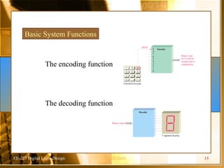
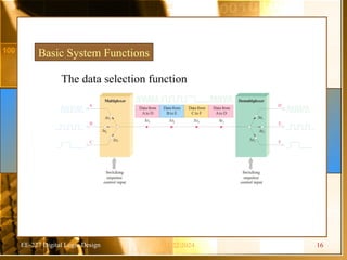
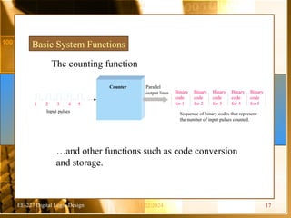
Basic System Functions
One type of storage function is the shift register,
that moves and stores data each time it is clocked.
0 0 0 0
0101
Initially
, the register contains onlyinvalid
data or all zeros as shown here.
1 0 0 0
010
First bit (1) is shifted serially into the
register.
0 1 0 0
01
Second bit (0) is shifted serially into
register and first bit is shifted right.
1 0 1 0
0
Third bit (1) is shifted into register and
the first and second bits are shifted right.
0 1 0 1
Fourth bit (0) is shifted into register and
the first, second,and third bits are shifted
right.The register now stores all four bits
and is full.
Serial bits
on input line
11/22/2024 18[E-2]](https://image.slidesharecdn.com/ch1intro-241122170242-675df225/85/Ch1-Intr-for-the-distributed-system-and-clock-18-320.jpg)